Table of Contents
Advertisement
Quick Links
Advertisement
Table of Contents

Subscribe to Our Youtube Channel
Related Manuals for IEI Technology KINO-9152G4


Summary of Contents for IEI Technology KINO-9152G4
- Page 1 KINO-9152G4 Mini-ITX Motherboard Page i Rev. 2.00 October, 2008...
- Page 2 KINO-9152G4 Mini-ITX Motherboard Revision Date Version Changes October, 2008 2.01 Updated JP10 and JP11 settings and descriptions Updated COM2 and COM6 descriptions October, 2008 2.00 Upgraded Intel® 915GM to Intel® 915GME October, 2007 1.01 Corrected reference to 240-pin DDR2 to 200-pin DDR2 September, 2007 1.00...
- Page 3 KINO-9152G4 Mini-ITX Motherboard Copyright COPYRIGHT NOTICE The information in this document is subject to change without prior notice in order to improve reliability, design and function and does not represent a commitment on the part of the manufacturer. In no event will the manufacturer be liable for direct, indirect, special, incidental, or consequential damages arising out of the use or inability to use the product or documentation, even if advised of the possibility of such damages.
- Page 4 Cautionary messages should also be heeded to help reduce the chance of losing data or damaging the KINO-9152G4. Cautions are easy to recognize. The word “caution” is written as “CAUTION,” both capitalized and bold and is followed. The text is the cautionary message.
- Page 5 “NOTE,” both capitalized and bold and is followed by text. The text is the cautionary message. A note message is shown below: NOTE: This is an example of a note message. Notes should always be read. Notes contain critical information about the KINO-9152G4. Please take note messages seriously. Page v...
-
Page 6: Packing List
KINO-9152G4 from or contact an IEI sales representative directly. To contact an IEI sales representative, please send an email to sales@iei.com.tw. The items listed below should all be included in the KINO-9152G4 package. 1 x KINO-9152G4 Mini-ITX Motherboard 1 x Audio Cable... -
Page 7: Table Of Contents
1.1.1 KINO-9152G4 Benefits..................2 1.1.2 KINO-9152G4 Features..................3 1.2 KINO-9152G4 O ..................3 VERVIEW 1.2.1 KINO-9152G4 Overview Photo................. 3 1.2.2 KINO-9152G4 Peripheral Connectors and Jumpers ........4 1.2.3 Technical Specifications..................6 2 DETAILED SPECIFICATIONS .................. 8 2.1 O ......................... 9 VERVIEW 2.2 D... - Page 8 KINO-9152G4 Mini-ITX Motherboard 2.6.5 PCI Interface....................23 2.6.5.1 Mini PCI slot (Optional) ................24 2.6.6 Real Time Clock ....................24 2.6.7 SATA Controller ....................24 2.6.8 USB Controller ....................25 2.6.9 PCIe Bus Overview ..................26 2.6.9.1 Broadcom BCM5787M PCIe GbE Chipset..........26 2.7 LPC B...
- Page 9 KINO-9152G4 Mini-ITX Motherboard 4.2 I ..............42 NTERNAL ERIPHERAL ONNECTORS 4.2.1 ATX Power Connector ..................42 4.2.2 Audio Connector (10-pin) ................44 4.2.3 Backlight Inverter Connector ................45 4.2.4 Battery Connector.................... 46 4.2.5 CompactFlash® Slot (Optional)..............47 4.2.6 Digital Input/Output (DIO) Connector............48 4.2.7 Fan Connectors (+12 V, 3-pin) ................
- Page 10 KINO-9152G4 Mini-ITX Motherboard 5.3.4 CF Card Installation ..................84 5.4 J ....................86 UMPER ETTINGS 5.4.1 AT/ATX Selection Jumper ................86 5.4.2 Clear CMOS Jumper..................87 5.4.3 CF Card Setup ....................88 5.4.4 COM2 Serial Port Selection Jumper ............... 89 5.4.5 COM6 Serial Port Selection Jumper ...............
- Page 11 KINO-9152G4 Mini-ITX Motherboard 6.3 A ......................112 DVANCED 6.3.1 CPU Configuration..................114 6.3.2 IDE Configuration ..................115 6.3.2.1 IDE Master, IDE Slave ................117 6.3.3 Super IO Configuration.................. 122 6.3.4 Hardware Health Configuration..............125 6.3.5 ACPI Configuration ..................126 6.3.6 Remote Access Configuration ................ 128 6.3.7 USB Configuration..................
- Page 12 KINO-9152G4 Mini-ITX Motherboard C DIGITAL I/O INTERFACE..................185 C.1 DIO I ................186 NTERFACE NTRODUCTION C.2 DIO C ................... 186 ONNECTOR INOUTS C.3 A ................187 SSEMBLY ANGUAGE AMPLES C.3.1 Enable the DIO Input Function..............187 C.3.2 Enable the DIO Output Function ..............187 D WATCHDOG TIMER ....................
- Page 13 KINO-9152G4 Mini-ITX Motherboard List of Figures Figure 1-1: KINO-9152G4 .......................2 Figure 1-2: KINO-9152G4 Overview [Front View] ................4 Figure 2-1: KINO-9152G4 Dimensions (mm)................9 Figure 2-2: External Interface Panel Dimensions (mm) ............10 Figure 2-3: Data Flow Block Diagram ..................11 Figure 2-4: Socket M........................12 Figure 2-5: Intel®...
- Page 14 Figure 4-18: RS-422/485 Serial Port Connector Location............67 Figure 4-19: COM 5 Connector Pinout Locations ..............68 Figure 4-20: USB Connector Pinout Locations .................69 Figure 4-21: KINO-9152G4 External Peripheral Interface Connector ........70 Figure 4-22: PS/2 Pinouts ......................71 Figure 4-23: RJ-45 Ethernet Connector..................72 Figure 4-24: COM1 Pinout Locations..................73...
- Page 15 KINO-9152G4 Mini-ITX Motherboard Figure 5-18: Backlight Inverter Connection................98 Figure 5-19: SO-DIMM Installation ....................99 Figure 5-20: PCIe x16 Installation .................... 100 Figure 5-21: SATA Drive Cable Connection................101 Figure 5-22: SATA Power Drive Connection................102 Figure 5-23: LAN Connection ....................103 Figure 5-24: PS/2 Keyboard/Mouse Connector ..............
- Page 16 KINO-9152G4 Mini-ITX Motherboard Figure 7-26: InstallShield Wizard Welcome Screen ............... 175 Figure 7-27: Audio Driver Software Configuration..............175 Figure 7-28: Audio Driver Digital Signal.................. 176 Figure 7-29: Audio Driver Installation..................176 Figure 7-30: Restart the Computer ..................177 Page xvi...
- Page 17 KINO-9152G4 Mini-ITX Motherboard List of Tables Table 1-1: Technical Specifications....................7 Table 2-1: Supported HDD Specifications..................23 Table 2-2: Power Consumption....................33 Table 3-1: Package List Contents ....................37 Table 4-1: Peripheral Interface Connectors ................41 Table 4-2: Rear Panel Connectors ....................42 Table 4-3: ATX Power Connector Pinouts .................43 Table 4-4: Audio Connector Pinouts (10-pin) ................45...
- Page 18 KINO-9152G4 Mini-ITX Motherboard Table 4-27: VGA Connector Pinouts...................74 Table 5-1: Jumpers ........................86 Table 5-2: AT/ATX Selection Jumper Settings ................87 Table 5-3: Clear CMOS Jumper Settings..................88 Table 5-4: CF Card Setup Jumper Settings ................89 Table 5-5: COM2 Serial Port Select Jumper Settings ...............90 Table 5-6: COM6 Serial Port Select Jumper Settings ...............91...
- Page 19 KINO-9152G4 Mini-ITX Motherboard BIOS Menus BIOS Menu 1: Main ........................111 BIOS Menu 2: Advanced ......................113 BIOS Menu 3: CPU Configuration .................... 114 BIOS Menu 4: IDE Configuration....................115 BIOS Menu 5: IDE Master and IDE Slave Configuration ............117 BIOS Menu 6: Super IO Configuration..................
-
Page 21: Introduction
KINO-9152G4 Mini-ITX Motherboard Chapter Introduction Page 1... -
Page 22: Introduction
Broadcom PCI Express Gigabit Ethernet (PCIe GbE). Storage options on the KINO-9152G4 include up to two SATA hard drives with transfer speeds of up to 1.5 Gb/s, and two IDE hard drives (a CompactFlash® slot is available as an option). -
Page 23: Kino-9152G4 Features
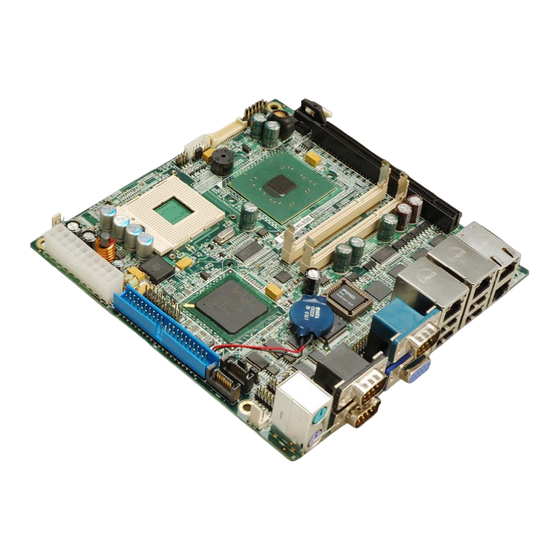
Multiple display options including VGA and 24-bit dual-channel LVDS 1.2 KINO-9152G4 Overview 1.2.1 KINO-9152G4 Overview Photo The KINO-9152G4 has a wide variety of internal and external peripheral connectors. A labeled photo of the peripheral connectors on the KINO-9152G4 is shown in Figure 1-2. Page 3... -
Page 24: Kino-9152G4 Peripheral Connectors And Jumpers
KINO-9152G4 Mini-ITX Motherboard Figure 1-2: KINO-9152G4 Overview [Front View] 1.2.2 KINO-9152G4 Peripheral Connectors and Jumpers The KINO-9152G4 has the following connectors on-board: 1 x ATX power connector 1 x Audio header 1 x CPU fan connector 1 x Digital I/O... - Page 25 2 x USB header Optional connectors for the KINO-9152G4 include: 1 x CompactFlash® slot 1 x Mini-PCI slot The KINO-9152G4 has the following external peripheral interface connectors on the board rear panel 4 x Ethernet connectors 1 x Keyboard connector...
-
Page 26: Technical Specifications
KINO-9152G4 Mini-ITX Motherboard 1.2.3 Technical Specifications KINO-9152G4 technical specifications are listed in Table 1-1. See Chapter 2 for details. Specification KINO-9152G4 Form Factor Mini-ITX Intel® Pentium M System CPU Intel® Celeron M Front Side Bus 400 MHz or 533 MHz Northbridge: Intel®... -
Page 27: Table 1-1: Technical Specifications
KINO-9152G4 Mini-ITX Motherboard Specification KINO-9152G4 Two 200-pin 400 MHz or 533 MHz dual channel SO-DIMMs Memory up to 2 GB SATA Two 1.5 Gb/s SATA drives Eight USB 2.0 devices supported (four external) Watchdog Timer Software programmable 1-255 sec. by super I/O... -
Page 28: Detailed Specifications
KINO-9152G4 Mini-ITX Motherboard Chapter Detailed Specifications Page 8... -
Page 29: Overview
KINO-9152G4 Mini-ITX Motherboard 2.1 Overview This chapter describes the specifications and on-board features of the KINO-9152G4 in detail. 2.2 Dimensions 2.2.1 Board Dimensions The dimensions of the board are listed below: Length: 170 mm Width: 170 mm Figure 2-1: KINO-9152G4 Dimensions (mm) -
Page 30: External Interface Panel Dimensions
KINO-9152G4 Mini-ITX Motherboard 2.2.2 External Interface Panel Dimensions External peripheral interface connector panel dimensions are shown in Figure 2-2. Figure 2-2: External Interface Panel Dimensions (mm) 2.3 Data Flow Figure 2-3 shows the data flow between the two on-board chipsets and other components installed on the motherboard and described in the following sections of this chapter. -
Page 31: Compatible Processors
KINO-9152G4 Mini-ITX Motherboard Figure 2-3: Data Flow Block Diagram 2.4 Compatible Processors 2.4.1 Compatible Processor Overview The KINO-9152G4 supports the following socket M processors: Intel® Pentium M Page 11... -
Page 32: Intel® 915Gme Northbridge Chipset
KINO-9152G4 Mini-ITX Motherboard Intel® Celeron M Figure 2-4: Socket M All the above processors communicate with the Intel® 915GME Northbridge chipset through a 400 MHz or 533 MHz FSB. 2.5 Intel® 915GME Northbridge Chipset 2.5.1 Overview The Intel® 915GME Northbridge chipset has a Generation 3.1 Intel® Integrated Graphics Engine and the Intel®... -
Page 33: Memory Support
Do not install DDR memory modules. If a DDR memory module is installed on the KINO-9152G4, the KINO-9152G4 may be irreparably damaged. The Intel® 915GME Northbridge chipset on the KINO-9152G4 supports two DDR2 200-pin SO-DIMMs with the following features: Two 200-pin SO-DIMMs... -
Page 34: Pcie X16
2.5.3 PCIe x16 The Intel® 915GME Northbridge chipset has a dedicated 16-lane PCIe port for a PCIe x16 graphics card. The PCIe x16 graphics card is connected to the KINO-9152G4 using the PCIe x16 expansion slot. Figure 2-7: PCIe x16 Expansion Slot Some of the PCIe x16 bus specifications are listed below. -
Page 35: Integrated Graphics
KINO-9152G4 Mini-ITX Motherboard 100 MHz differential reference clock PCIe power management support L0, L1, L2/L3 ready, L3 Hierarchical PCI compliant configuration mechanism for downstream components PCIe extended configuration space PCIe enhanced addressing mechanism Supports traditional PCI traffic Supports traditional AGP traffic APIC and MSI messaging support 2.5.4 Integrated Graphics... -
Page 36: Analog Vga Support
KINO-9152G4 Mini-ITX Motherboard Figure 2-8: VGA and LVDS 2.5.4.1 Analog VGA Support A DB-15 VGA connector on the external peripheral interface connector panel is interfaced to the Intel® 915GME graphics engine. The Intel® 915GME internal graphics engine, with an integrated 400 MHz RAMDAC and hot plug CRT support, supports analog CRT... -
Page 37: Direct Media Interface (Dmi)
KINO-9152G4 Mini-ITX Motherboard Compliant with ANSI/TIA/EIA -644-2001 spec Integrated dual channel LVDS interface supported on Display Pipe B only Supports 25 to 112 MHz single/dual channel LVDS interface Single channel LVDS interface support: 1 x 24-bit Dual channels LVDS interface support: 2 x 24-bit... -
Page 38: Intel® Ich6M Southbridge Chipset
KINO-9152G4 Mini-ITX Motherboard Figure 2-9: Direct Media Interface Features of the Intel® 915GME DMI are listed below: Chip-to-chip interface between GMCH and Intel® ICH6M Configurable as x2 or x4 DMI lanes 2 GB/s point-to-point DMI to Intel® ICH6M (1 GB/s each direction) 100 MHz reference clock (shared with PCI Express Graphics Attach). -
Page 39: Audio Codec '97 Controller
Integrated SATA host controller with DMA operations interfaced to two SATA connectors on the KINO-9152G4 Integrated IDE controller supports Ultra ATA 100/66/33 Supports the eight USB 2.0 devices on the KINO-9152G4 with four UHCI controllers and one EHCI controller Complies with System Management Bus (SMBus) Specification, Version 2.0 Supports Audio Codec ’97 (AC’97) Revision 2.3 and Intel®... -
Page 40: Realtek Alc655 Ac'97 Codec
KINO-9152G4 Mini-ITX Motherboard 2.6.2.1 Realtek ALC655 AC’97 Codec The Realtek ALC655 is connected to onboard audio connectors, which are then connected to compliant audio devices. The Realtek ALC655 is a 16-bit, full-duplex AC'97 Rev. 2.3 compatible six-channel audio codec. The codec and the audio connectors are shown in Figure 2-11. -
Page 41: Ide Interface
IDE hard disks. PIO IDE transfers up to 16 MB/s and Ultra ATA transfers up to 100 MB/s. The CompactFlash® card slot on the solder side of the KINO-9152G4 is an optional extra and is not included with the standard version of the KINO-9152G4. -
Page 42: Figure 2-12: Ide Connector
KINO-9152G4 Mini-ITX Motherboard Figure 2-12: IDE Connector Figure 2-13: CompactFlash® Slot (Optional) The integrated IDE interface is able to support one CompactFlash® Type II card and the following IDE HDDs: Page 22... -
Page 43: Low Pin Count (Lpc) Interface
KINO-9152G4 Mini-ITX Motherboard Ultra ATA/100, with data transfer rates up to 100 MB/s Ultra ATA/66, with data transfer rates up to 66 MB/s Ultra ATA/33, with data transfer rates up to 33 MB/s Specification Ultra ATA/100 Ultra ATA/66 Ultra ATA/33... -
Page 44: Mini Pci Slot (Optional)
The PCI bus is connected to the Mini PCI slot located on the solder side of the KINO-9152G4. The Mini PCI socket can support standard Mini PCI cards. The Mini-PCI slot is an optional extra and is not included on the standard KINO-9152G4. -
Page 45: Usb Controller
Up to eight high-speed, full-speed or low-speed USB devices are supported by the Intel® ICH6M on the KINO-9152G4. High-speed USB 2.0, with data transfers of up to 480 MB/s, is enabled with the Intel® ICH6M integrated Enhanced Host Controller Interface (EHCI) compliant host controller. -
Page 46: Pcie Bus Overview
The Intel® ICH6M Southbridge chipset has four PCIe x1 lanes. The four PCIe x1 lanes are interfaced through Broadcom BCM5787M PCIe GbE chipsets to Ethernet ports on the rear panel of the KINO-9152G4. 2.6.9.1 Broadcom BCM5787M PCIe GbE Chipset The Broadcom BCM5787M PCI Express (PCIe) GbE controller is a 10/100/1000BASE-T Ethernet LAN controller. -
Page 47: Lpc Bus Components
KINO-9152G4 Mini-ITX Motherboard Figure 2-17: Broadcom PCIe GbE Controllers Some of the BCM5787 controller features are listed below: Integrated 10/100/1000BASE-T transceiver Automatic MDI crossover function PCIe v1.0a 10/100/1000BASE-T full/half-duplex MAC Wake on LAN support meeting the ACPI requirements Statistics for SNMP MIB II, Ethernet-like MIB, and Ethernet MIB (802.3z,... -
Page 48: Bios Chipset
KINO-9152G4 Mini-ITX Motherboard Super I/O chipset Serial port chipset Digital I/O chipset 2.7.2 BIOS Chipset The BIOS chipset has a licensed copy of AMI BIOS installed on the chipset. Some of the BIOS features are listed below: AMI Flash BIOS... -
Page 49: Super I/O Lpc Interface
KINO-9152G4 Mini-ITX Motherboard Figure 2-19: iTE IT8712F Super I/O Some of the features of the iTE IT8712F chipset are listed below: PC98/99/2001, ACPI and LANDesk Compliant Enhanced Hardware Monitor Fan Speed Controller Consumer Remote Control (TV remote) IR with power-up feature... -
Page 50: Super I/O Enhanced Hardware Monitor
Supports mouse double-click and/or mouse move power on events 2.7.4 Fintek F81216D LPC Serial Port Chipset The KINO-9152G4 has a Fintek F81216D chipset onboard enables the addition of four additional UART serial ports (COM3, COM4, COM5 and COM6). UART includes 16-byte send/receive FIFO. -
Page 51: Lattice Semiconductor Lc4064 V Lpc Digital I/O Chipset
Powered by 3 Vcc 2.7.5 Lattice Semiconductor LC4064 V LPC Digital I/O Chipset The KINO-9152G4 has a Lattice Semiconductor digital I/O chipset onboard that enables a 24-bit Digital I/O. The LC4064 V chipset consists of multiple 36-input, 16 macrocell Generic Logic Blocks interconnected by a Global Routing Pool. Output Routing Pools (ORPs) connect the GLBs to the I/O Blocks that contain multiple I/O cells. -
Page 52: Environmental And Power Specifications
Three thermal inputs on the KINO-9152G4 Super I/O Enhanced Hardware Monitor monitor the following temperatures: CPU temperature System temperature 1 System temperature 2 Eight voltage inputs on the KINO-9152G4 Super I/O Enhanced Hardware Monitor monitor the following voltages: CPU Core +2.5 V +3.3 V +5.0 V... -
Page 53: Operating Temperature And Temperature Control
Northbridge and Southbridge chipsets to ensure the operating temperature of these chips remain low. 2.8.3 Power Consumption Table 2-2 shows the power consumption for the KINO-9152G4 running with a 2.13GHz Intel® Pentium M processor with 1 GB of DDR2 memory. Voltage... -
Page 54: Unpacking
KINO-9152G4 Mini-ITX Motherboard Chapter Unpacking Page 34... -
Page 55: Anti-Static Precautions
Electrostatic discharge (ESD) can cause serious damage to electronic components, including the KINO-9152G4. Dry climates are especially susceptible to ESD. It is therefore critical that whenever the KINO-9152G4, or any other electrical component is handled, the following anti-static precautions are strictly adhered to. -
Page 56: Unpacking Checklist
If any of the components listed in the checklist below are missing, do not proceed with the installation. Contact the IEI reseller or vendor the KINO-9152G4 was purchased from or contact an IEI sales representative directly by sending an email to sales@iei.com.tw. -
Page 57: Table 3-1: Package List Contents
KINO-9152G4 Mini-ITX Motherboard Quantity Item and Part Number Image Mini jumper pack Quick Installation Guide Utility CD Table 3-1: Package List Contents Page 37... -
Page 58: Connector Pinouts
KINO-9152G4 Mini-ITX Motherboard Chapter Connector Pinouts Page 38... -
Page 59: Peripheral Interface Connectors
KINO-9152G4 Mini-ITX Motherboard 4.1 Peripheral Interface Connectors Section 4.1.2 shows peripheral interface connector locations. Section 4.1.2 lists all the peripheral interface connectors. 4.1.1 Layout Figure 4-1 shows the on-board peripheral connectors, rear panel peripheral connectors and on-board jumpers. Figure 4-1: Connector and Jumper Locations... -
Page 60: Peripheral Interface Connectors
KINO-9152G4 Mini-ITX Motherboard Figure 4-2: Connector and Jumper Locations (Solder Side) (Optional) 4.1.2 Peripheral Interface Connectors Table 4-1 shows a list of the peripheral interface connectors on the KINO-9152G4. Detailed descriptions of these connectors can be found below. Connector Type... -
Page 61: External Interface Panel Connectors
USB1 USB connector 8-pin header USB2 Table 4-1: Peripheral Interface Connectors 4.1.3 External Interface Panel Connectors Table 4-2 lists the rear panel connectors on the KINO-9152G4. Detailed descriptions of these connectors can be found below. Connector Type Label Ethernet connector... -
Page 62: Internal Peripheral Connectors
Internal peripheral connectors are found on the motherboard and are only accessible when the motherboard is outside of the chassis. This section has complete descriptions of all the internal, peripheral connectors on the KINO-9152G4. 4.2.1 ATX Power Connector CN Label:... -
Page 63: Figure 4-3: Atx Power Connector Pinout Locations
KINO-9152G4 Mini-ITX Motherboard Figure 4-3: ATX Power Connector Pinout Locations PIN NO. DESCRIPTION PIN NO. DESCRIPTION 3.3 V 3.3 V 3.3 V -12 V PS-ON PW-OK -5 V VCC5SBY VCC12 Table 4-3: ATX Power Connector Pinouts Page 43... -
Page 64: Audio Connector (10-Pin)
KINO-9152G4 Mini-ITX Motherboard 4.2.2 Audio Connector (10-pin) CN Label: 10-pin header CN Type: CN Location: See Figure 4-4 CN Pinouts: See Table 4-4 The 10-pin audio connector is connected to external audio devices including speakers and microphones for the input and output of audio signals to and from the system. -
Page 65: Backlight Inverter Connector
See Figure 4-5 CN Pinouts: See Table 4-5 The backlight inverter connector provides the backlight on the LCD display connected to the KINO-9152G4 with +12 V of power. Figure 4-5: Panel Backlight Connector Pinout Locations PIN NO. DESCRIPTION VCC12 V... -
Page 66: Battery Connector
KINO-9152G4 Mini-ITX Motherboard PIN NO. DESCRIPTION GROUND GROUND Table 4-5: Panel Backlight Connector Pinouts 4.2.4 Battery Connector CN Label: CN Type: 2-pin wafer (1x2) CN Location: See Figure 4-6 CN Pinouts: See Table 4-6 The battery connector is connected to a backup battery. The battery connector can also used to reset the CMOS memory if the incorrect BIOS settings have been made and the system cannot boot up. -
Page 67: Compactflash® Slot (Optional)
KINO-9152G4 Mini-ITX Motherboard 4.2.5 CompactFlash® Slot (Optional) CN Label: CF1 (solder side) 50-pin header (2x25) CN Type: CN Location: See Figure 4-7 CN Pinouts: See Table 4-7 A CF Type I or Type II memory card is inserted to the CF socket on the solder side of the KINO-9152G4. -
Page 68: Digital Input/Output (Dio) Connector
KINO-9152G4 Mini-ITX Motherboard PIN NO. DESCRIPTION PIN NO. DESCRIPTION SDD5 SDD13 SDD6 SDD14 SDD7 SDD15 SDCS1 SDCS3 GROUND SDIOR SDIOW IRQ15 CSEL IDERST SHDRDY SDA2 SDDREQ SDA1 SDDACK SDA0 HDD_LED2 SDD0 SDD1 SDD8 SDD2 SDD9 SDD10 CFD2 GROUND Table 4-7: CF Card Socket Pinouts 4.2.6 Digital Input/Output (DIO) Connector... -
Page 69: Figure 4-8: Dio Connector Locations
KINO-9152G4 Mini-ITX Motherboard The digital input/output connector is managed through a Super I/O chip. The DIO connector pins are user programmable. The DIO provides 24-bit input/output capabilities, up to 12-bits input and 12-bits output. The interrupts for programming the digital I/O port... -
Page 70: Fan Connectors (+12 V, 3-Pin)
KINO-9152G4 Mini-ITX Motherboard PIN NO. DESCRIPTION PIN NO. DESCRIPTION D_8IN5 D_8OUT5 D_8IN6 D_8OUT6 D_8IN7 D_8OUT7 Table 4-8: DIO Connector Pinouts 4.2.7 Fan Connectors (+12 V, 3-pin) CN Label: CPU_FAN, SYS_FAN 3-pin header CN Type: CN Location: See Figure 4-9 CN Pinouts:... -
Page 71: Front Panel Connector (12-Pin)
KINO-9152G4 Mini-ITX Motherboard PIN NO. DESCRIPTION Fan Speed Detect +12 V Table 4-9: +12 V Fan Connector Pinouts 4.2.8 Front Panel Connector (12-pin) CN Label: CN Type: 12-pin header (2x6) See Figure 4-10 CN Location: CN Pinouts: See Table 4-10 The front panel connector connects to external switches and indicators to monitor and controls the motherboard. -
Page 72: Ide Connector (40-Pin)
KINO-9152G4 Mini-ITX Motherboard Figure 4-10: Front Panel Connector Pinout Locations FUNCTION DESCRIPTION FUNCTION DESCRIPTION Power LED LED+ Buzzer BUZZER- LED- Power PWR+ Button PWR- HDD LED HDD LED+ Reset RESET HDD LED- Table 4-10: Front Panel Connector Pinouts 4.2.9 IDE Connector (40-pin) -
Page 73: Figure 4-11: Ide Device Connector Locations
KINO-9152G4 Mini-ITX Motherboard CN Pinouts: See Table 4-11 One 40-pin IDE device connector on the KINO-9152G4 supports connectivity to two hard disk drives. Figure 4-11: IDE Device Connector Locations PIN NO. DESCRIPTION PIN NO. DESCRIPTION RESET# GROUND DATA 7 DATA 8... -
Page 74: Infrared Interface Connector (5-Pin)
KINO-9152G4 Mini-ITX Motherboard PIN NO. DESCRIPTION PIN NO. DESCRIPTION DATA 4 DATA 11 DATA 3 DATA 12 DATA 2 DATA 13 DATA 1 DATA 14 DATA 0 DATA 15 GROUND IDE DRQ GROUND IOW# GROUND IOR# GROUND IDE CHRDY GROUND IDE DACK GROUND–DEFAULT... -
Page 75: Lvds Lcd Connector
KINO-9152G4 Mini-ITX Motherboard Figure 4-12: Infrared Connector Pinout Locations PIN NO. DESCRIPTION CIRRX IRRX IRTX Table 4-12: Infrared Connector Pinouts 4.2.11 LVDS LCD Connector CN Label: LVDS1 30-pin crimp (2x10) CN Type: CN Location: See Figure 4-13 CN Pinouts: See Table 4-13 The 30-pin LVDS LCD connector can be connected to single channel or dual channel, 18-bit or 24-bit LVDS panel. -
Page 76: Figure 4-13: Lvds Lcd Connector Pinout Locations
KINO-9152G4 Mini-ITX Motherboard Figure 4-13: LVDS LCD Connector Pinout Locations PIN NO. DESCRIPTION PIN NO. DESCRIPTION GROUND GROUND LVDS_Y0+ LVDS_Y0- LVDS_Y1+ LVDS_Y1- LVDS_Y2+ LVDS_Y2- LVDS_CLK+ LVDS_CLK- LVDS_Y3+ LVDS_Y3+ GROUND GROUND LVDSB_Y0+ LVDSB_Y0- Page 56... -
Page 77: Mini Pci Slot (Optional)
KINO-9152G4 Mini-ITX Motherboard PIN NO. DESCRIPTION PIN NO. DESCRIPTION LVDSB_Y1+ LVDSB_Y1- LVDSB_Y2+ LVDSB_Y2- LVDSB_CLK+ LVDSB_CLK- LVDSB_Y3+ LVDSB_Y3- GROUND GROUND VCC_LVDS VCC_LVDS VCC_LVDS VCC_LVDS Table 4-13: LVDS LCD Port Connector Pinouts 4.2.12 Mini PCI Slot (Optional) CN Label: MINI_PCI1 (solder side) -
Page 78: Figure 4-14: Mini Pci Slot Location
KINO-9152G4 Mini-ITX Motherboard Figure 4-14: Mini PCI Slot Location PIN NO. DESCRIPTION PIN NO. DESCRIPTION Page 58... - Page 79 KINO-9152G4 Mini-ITX Motherboard PIN NO. DESCRIPTION PIN NO. DESCRIPTION PINTD# VCC5 VCC3 PINTC# VCC3SB CLK_MPCI PCI_RST1# VCC3 PCI_REQ2# PCI_GNT2# VCC3 PAD31 PPME# PAD29 PAD30 PAD27 VCC3 PAD25 PAD28 PAD26 PC/BE3# PAD24 PAD23 PAD29 PAD21 PAD22 PAD19 PAD20 PPAR PAD17 PAD18...
- Page 80 KINO-9152G4 Mini-ITX Motherboard PIN NO. DESCRIPTION PIN NO. DESCRIPTION PC/BE2# PAD16 PIRDY# VCC3 PFRAME# PTRDY# SERR# PSTOP# VCC3 PERR# PDEVSEL# PC/BE1# PAD14 PAD15 PAD13 PAD12 PAD11 PAD10 PAD9 PAD8 PC/BE0# PAD7 VCC3 VCC3 PAD6 PAD5 PAD4 PAD2 PAD3 PAD0 VCC5...
-
Page 81: Pci Express X16 Slot
KINO-9152G4 Mini-ITX Motherboard PIN NO. DESCRIPTION PIN NO. DESCRIPTION VCC3SB Table 4-14: Mini PCI Slot Pinouts 4.2.13 PCI Express x16 Slot CN Label: PCIE1 PCIe x16 expansion slot CN Type: CN Location: See Figure 4-15 CN Pinouts: See Table 4-15 (Side A) Table 4-16 (Side B) PCIe x16 expansion devices can be inserted into the PCIe x16 slot. -
Page 82: Figure 4-15: Pcie X16 Expansion Slot Location
KINO-9152G4 Mini-ITX Motherboard Figure 4-15: PCIe x16 Expansion Slot Location NAME NAME NAME NAME Name HSIn(1) HSIp(6) HSIp(11) PRSNT#1 HSIn(6) HSIn(11) +12v Page 62... -
Page 83: Table 4-15: Pcie X16 Side A Pinouts
KINO-9152G4 Mini-ITX Motherboard NAME NAME NAME NAME +12v HSIp(2) HSIn(2) HSIp(7) HSIp(12) JTAG2 HSIn(7) HSIn(12) JTAG3 JTAG4 HSIp(3) RSVD JTAG5 HSIn(3) HSIp(13) +3.3v HSIp(8) HSIn(13) +3.3v RSVD HSIn(8) PWRGD RSVD HSIp(14) REFCLK+ HSIp(4) HSIp(9) HSIn(14) REFCLK- HSIn(4) HSIn(9) HSIp(0) HSIp(15) -
Page 84: Sata Drive Connectors
KINO-9152G4 Mini-ITX Motherboard NAME NAME NAME NAME WAKE# HSOp(14) RSVD HSOp(4) HSOp(9) HSOn(14) HSOn(4) HSOn(9) HSOp(0) HSOn(0) HSOp(15) HSOp(5) HSOp(10) HSOn(15) PRSNT#2 HSOn(5) HSOn(10) PRSNT#2 HSOp(1) RSVD#2 HSOn(1) HSOp(6) HSOp(11) HSOn(6) HSOn(11) Table 4-16: PCIe x16 Side B Pinouts 4.2.14 SATA Drive Connectors... -
Page 85: Serial Port Connector (Com2 And Com6) (Rs-232)
KINO-9152G4 Mini-ITX Motherboard Figure 4-16: SATA Drive Connector Locations PIN NO. DESCRIPTION Table 4-17: SATA Drive Connector Pinouts 4.2.15 Serial Port Connector (COM2 and COM6) (RS-232) CN Label: COM2 and COM6 CN Type: 10-pin header (2x5) CN Location: See Figure 4-17... -
Page 86: Serial Port Connector (Com2 And Com6) (Rs-422 And Rs-485)
KINO-9152G4 Mini-ITX Motherboard Figure 4-17: RS-232 Serial Port Connector Location PIN NO. DESCRIPTION PIN NO. DESCRIPTION Data Carrier Direct (DCD) Data Set Ready (DSR) Receive Data (RXD) Request To Send (RTS) Transmit Data (TXD) Clear To Send (CTS) Data Terminal Ready (DTR) -
Page 87: Serial Port Connector (Com5)
KINO-9152G4 Mini-ITX Motherboard CN Location: See Figure 4-18 CN Pinouts: See Table 4-19 The 12-pin connectors provide serial port communication selection, and RS-422 and RS-485 connections. JP10 provides the COM2 RS-422 and RS-485 ports, while JP11 provides the COM6 RS-422 and RS-485 ports. -
Page 88: Figure 4-19: Com 5 Connector Pinout Locations
KINO-9152G4 Mini-ITX Motherboard CN Location: See Figure 4-19 CN Pinouts: See Table 4-20 The 10-pin serial port connector provides a second RS-232 serial communications channel. The COM 5 serial port connector can be connected to external RS-232 serial port devices. -
Page 89: Usb Connectors (Internal)
KINO-9152G4 Mini-ITX Motherboard 4.2.18 USB Connectors (Internal) CN Label: USB1 and USB2 8-pin header (2x4) CN Type: CN Location: See Figure 4-20 CN Pinouts: See Table 4-21 The 2x4 USB pin connectors each provide connectivity to two USB 1.1 or two USB 2.0 ports. -
Page 90: External Peripheral Interface Connector Panel
+5 V Table 4-21: USB Port Connector Pinouts 4.3 External Peripheral Interface Connector Panel Figure 4-21 shows the KINO-9152G4 external peripheral interface connector (EPIC) panel. The KINO-9152G4 EPIC panel consists of the following: 1 x Dual PS/2 connector 4 x RJ-45 LAN connectors... -
Page 91: Lan Connectors
See Figure 4-21 (see 4 and 5) CN Pinouts: See Table 4-23 The KINO-9152G4 is equipped with four built-in RJ-45 Ethernet controllers. The controllers can connect to the LAN through the four RJ-45 LAN connectors. There are two Page 71... -
Page 92: Serial Port Connectors (Com1, Com3 And Com4)
KINO-9152G4 Mini-ITX Motherboard LEDs on the connector indicating the status of LAN. The pin assignments are listed in the following table: DESCRIPTION DESCRIPTION TXA+ TXC- TXA- TXB- TXB+ TXD+ TXC+ TXD- Table 4-23: LAN Pinouts Figure 4-23: RJ-45 Ethernet Connector The RJ-45 Ethernet connector has two status LEDs, one green and one yellow. -
Page 93: Usb Connector
CN Type: Dual USB ports CN Location: See Figure 4-21 CN Pinouts: See Table 4-26 The KINO-9152G4 has four external USB 2.0 ports. The ports connect to both USB 2.0 and USB 1.1 devices. PIN NO. DESCRIPTION PIN NO. DESCRIPTION... -
Page 94: Vga Connector
CRT_COM1 15-pin Female CN Type: CN Location: See Figure 4-21 CN Pinouts: See Figure 4-25 and Table 4-27 The KINO-9152G4 has a single 15-pin female connector for connectivity to standard display devices. Figure 4-25: VGA Connector DESCRIPTION DESCRIPTION GREEN BLUE... -
Page 95: Installation
KINO-9152G4 Mini-ITX Motherboard Chapter Installation Page 75... -
Page 96: Anti-Static Precautions
Electrostatic discharge (ESD) can cause serious damage to electronic components, including the KINO-9152G4. Dry climates are especially susceptible to ESD. It is therefore critical that whenever the KINO-9152G4, or any other electrical component is handled, the following anti-static precautions are strictly adhered to. -
Page 97: Installation Considerations
KINO-9152G4 is installed. All installation notices pertaining to the installation of the KINO-9152G4 should be strictly adhered to. Failing to adhere to these precautions may lead to severe damage of the KINO-9152G4 and injury to the person installing the motherboard. 5.2.1 Installation Notices... -
Page 98: Installation Checklist
KINO-9152G4 Mini-ITX Motherboard DO NOT do the following before or during the installation of the KINO-9152G4: DO NOT remove any of the stickers on the PCB board. These stickers are required for warranty validation. DO NOT use the product before verifying all the cables and power connectors are properly connected. -
Page 99: Cpu, Cpu Cooling Kit And Dimm Installation
Running a CPU without a cooling kit may also result in injury to the user. The CPU, CPU cooling kit and DIMM are the most critical components of the KINO-9152G4. If one of these component is not installed the KINO-9152G4 cannot run. 5.3.1 Socket M CPU Installation WARNING: CPUs are expensive and sensitive components. -
Page 100: Figure 5-1: Make Sure The Cpu Socket Retention Screw Is Unlocked
KINO-9152G4 Mini-ITX Motherboard Step 1: Unlock the CPU retention screw. When shipped, the retention screw of the CPU socket should be in the unlocked position. If it is not in the unlocked position, use a screwdriver to unlock the screw. See Figure 5-1. -
Page 101: Cooling Kit Installation
KINO-9152G4 Mini-ITX Motherboard Step 7: Lock the retention screw. Rotate the retention screw into the locked position. See Figure 5-2.Step 0: Figure 5-2: Lock the CPU Socket Retention Screw 5.3.2 Cooling Kit Installation Figure 5-3: IEI CF-479B-RS Cooling Kit An IEI Socket M CPU cooling kit (Figure 5-3) can be purchased separately. The cooling kit comprises a CPU heat sink and a cooling fan. -
Page 102: Figure 5-4: Cooling Kit Support Bracket
KINO-9152G4 Mini-ITX Motherboard WARNING: Do not wipe off (accidentally or otherwise) the pre-sprayed layer of thermal paste on the bottom of the heat sink. The thermal paste between the CPU and the heat sink is important for optimum heat dissipation. -
Page 103: So-Dimm Installation
KINO-9152G4. Please make sure the purchased SO-DIMM complies with the memory specifications of the KINO-9152G4. SO-DIMM specifications compliant with the KINO-9152G4 are listed in Chapter 2. To install a SO-DIMM into a SO-DIMM socket, please follow the steps below and refer to Figure 5-6. -
Page 104: Cf Card Installation
The KINO-9152G4 can support both CF Type I cards and CF Type II cards. For the complete specifications of the supported CF cards please refer to Chapter 2. To install the a CF card (Type 1 or Type 2) onto the KINO-9152G4, please follow the steps below: Page 84... -
Page 105: Figure 5-7: Cf Card Installation
KINO-9152G4 Mini-ITX Motherboard Step 1: Locate the CF card socket. Place the KINO-9152G4 on an anti-static pad with the solder side facing up. Locate the CF card. Step 2: Align the CF card. Make sure the CF card is properly aligned with the CF socket. -
Page 106: Jumper Settings
Jumper Locations jumper means removing the plastic clip from a jumper. Before the KINO-9152G4 is installed in the system, the jumpers must be set in accordance with the desired configuration. The jumpers on the KINO-9152G4 are listed in Table 5-1. -
Page 107: Clear Cmos Jumper
KINO-9152G4 Mini-ITX Motherboard Jumper Type: 2-pin header Jumper Settings: See Table 5-2 Jumper Location: See Figure 5-8 The AT/ATX Selection Jumper selects whether to use AT or ATX power. The AT/ATX Selection Jumper settings are shown in Table 5-3. AT Power Select... -
Page 108: Cf Card Setup
KINO-9152G4 Mini-ITX Motherboard If the KINO-9152G4 fails to boot due to improper BIOS settings, the Clear CMOS Jumper resets the system BIOS information. To do this, use the jumper cap to close pins 2 and 3 for a few seconds then reinstall the jumper clip back to pins 1 and 2. -
Page 109: Com2 Serial Port Selection Jumper
KINO-9152G4 Mini-ITX Motherboard Jumper Type: 2-pin header Jumper Settings: See Table 5-4 Jumper Location: See Figure 5-10 The CF Card Setup jumper sets the CF Type I card or CF Type II cards as either the slave device or the master device. CF Card Setup jumper settings are shown in Table 5-4. -
Page 110: Com6 Serial Port Selection Jumper
KINO-9152G4 Mini-ITX Motherboard Serial Port Setting Description RS-232 Default 9-10 RS-422 11-12 RS-485 Table 5-5: COM2 Serial Port Select Jumper Settings The jumper location is shown in Figure 5-12. Figure 5-11: COM2 Serial Port Selection Jumper Location 5.4.5 COM6 Serial Port Selection Jumper... -
Page 111: Fsb Setup Jumper
See Table 5-7 Jumper Location: See Figure 5-13 The clear FSB setup jumper enables a user to select the FSB speed on the KINO-9152G4. The FSB Setup jumper settings are shown in Table 5-3. FSB Setup Description Short 1 – 2... -
Page 112: Lvds Voltage Selection
Figure 5-13: FSB Setup Jumper 5.4.7 LVDS Voltage Selection WARNING: Permanent damage to the screen and KINO-9152G4 may occur if the wrong voltage is selected with this jumper. Please refer to the user guide that cam with the monitor to select the correct voltage. -
Page 113: Chassis Installation
WARNING: Airflow is critical to the cooling of the CPU and other onboard components. The chassis in which the KINO-9152G4 must have air vents to allow cool air to move into the system and hot air to move out. Page 93... -
Page 114: Motherboard Installation
Table 5-9: IEI Provided Cables 5.6.2 ATA Flat Cable Connection The ATA 66/100 flat cable connects to the KINO-9152G4 to one or two IDE devices. To connect an IDE HDD to the KINO-9152G4 please follow the instructions below. Step 1: Locate the IDE connector. -
Page 115: Dual Rs-232 Cable With Slot Bracket
KINO-9152G4 Mini-ITX Motherboard Figure 5-15: IDE Cable Connection Step 3: Connect the cable to an IDE device. Connect the two connectors on the other side of the cable to one or two IDE devices. Make sure that pin 1 on the cable corresponds to pin 1 on the connector. -
Page 116: Lvds Lcd Installation
0: 5.6.4 LVDS LCD Installation The KINO-9152G4 can be connected to an LVDS LCD screen through the 30-pin LVDS crimp connector on the board. To connect an LVDS LCD to the KINO-9152G4, please follow the steps below. -
Page 117: Figure 5-17: Lvds Connector
KINO-9152G4 Mini-ITX Motherboard WARNING: The diagram below is merely for illustration. The configuration and connection of the cables from the LVDS LCD screen being installed may be different. Please refer to the installation manual that came with the LVDS LCD screen. -
Page 118: Mini Pci Installation
KINO-9152G4 Mini-ITX Motherboard Figure 5-18: Backlight Inverter Connection 5.6.5 Mini PCI Installation A Mini PCI expansion card can be installed on the motherboard using the optional Mini PCI expansion slot. To install a Mini PCI card into the Mini PCI socket, please follow the steps below and refer to Figure 5-6. -
Page 119: Pcie X16 Expansion Card Installation
Step 0: 5.6.6 PCIe x16 Expansion Card Installation A PCIe x16 expansion card can be installed on the KINO-9152G4 using the PCIe x16 expansion slot. To install a PCIe expansion card into the PCIe socket, please follow the steps below and refer to Figure 5-6. -
Page 120: Sata Drive Connection
Step 0: 5.6.7 SATA Drive Connection The KINO-9152G4 is shipped with two SATA drive cables and one SATA drive power cable. To connect the SATA drives to the connectors, please follow the steps below. Step 1: Locate the connectors. -
Page 121: Figure 5-21: Sata Drive Cable Connection
KINO-9152G4 Mini-ITX Motherboard Step 2: Insert the cable connector. Press the clip on the connector at the end of the SATA cable and insert the cable connector into the onboard SATA drive connector. See Figure 5-21. Figure 5-21: SATA Drive Cable Connection Step 3: Connect the cable to the SATA disk. -
Page 122: External Peripheral Interface Connection
RJ-45 Ethernet cable connectors PS/2 devices Serial port devices USB devices VGA monitors To install these devices, connect the corresponding cable connector from the actual device to the corresponding KINO-9152G4 external peripheral interface connector making sure the pins are properly aligned. Page 102... -
Page 123: Lan Connection
Step 0: 5.7.2 PS/2 Keyboard and Mouse Connection The KINO-9152G4 has a dual PS/2 connector on the external peripheral interface panel. The dual PS/2 connector is used to connect to a keyboard and mouse to the system. Follow the steps below to connect a keyboard and mouse to the KINO-9152G4. -
Page 124: Serial Device Connection
Step 0: Figure 5-24: PS/2 Keyboard/Mouse Connector 5.7.3 Serial Device Connection The KINO-9152G4 has a single female DB-9 connector on the external peripheral interface panel for a serial device. Follow the steps below to connect a serial device to the KINO-9152G4. -
Page 125: Usb Connection
KINO-9152G4 Mini-ITX Motherboard Figure 5-25: Serial Device Connector Step 3: Secure the connector. Secure the serial device connector to the external interface by tightening the two retention screws on either side of the connector. Step 0: 5.7.4 USB Connection The external USB Series "A" receptacle connectors provide easier and quicker access to external USB devices. -
Page 126: Vga Monitor Connection
Figure 5-26: USB Connector 5.7.5 VGA Monitor Connection The KINO-9152G4 has a single female DB-15 connector on the external peripheral interface panel. The DB-15 connector is connected to a CRT or VGA monitor. To connect a monitor to the KINO-9152G4, please follow the instructions below. -
Page 127: Figure 5-27: Vga Connector
KINO-9152G4 Mini-ITX Motherboard Figure 5-27: VGA Connector Step 4: Secure the connector. Secure the DB-15 VGA connector from the VGA monitor to the external interface by tightening the two retention screws on either side of the connector. Step 0: Page 107... -
Page 128: Ami Bios
KINO-9152G4 Mini-ITX Motherboard Chapter AMI BIOS Page 108... -
Page 129: Introduction
KINO-9152G4 Mini-ITX Motherboard 6.1 Introduction A licensed copy of AMI BIOS is preprogrammed into the ROM BIOS. The BIOS setup program allows users to modify the basic system configuration. This chapter describes how to access the BIOS setup program and the configuration options that may be changed. -
Page 130: Getting Help
KINO-9152G4 Mini-ITX Motherboard Function F1 key General help, only for Status Page Setup Menu and Option Page Setup Menu F2 /F3 key Change color from total 16 colors. F2 to select color forward. F10 key Save all the CMOS changes, only for Main Menu Table 6-1: BIOS Navigation Keys 6.1.3 Getting Help... -
Page 131: Main
KINO-9152G4 Mini-ITX Motherboard 6.2 Main The Main BIOS menu (BIOS Menu 1) appears when the BIOS Setup program is entered. The Main menu gives an overview of the basic system information. BIOS Menu 1: Main System Overview The System Overview lists a brief summary of different system components. The fields in System Overview cannot be changed. -
Page 132: Advanced
KINO-9152G4 Mini-ITX Motherboard Type: Names the currently installed processor Speed: Lists the processor speed Count: The number of CPUs on the motherboard System Memory: Displays the auto-detected system memory. Size: Lists memory size The System Overview field also has two user configurable fields: System Time [hh:mm:ss] Use the System Time option to set the system time. -
Page 133: Bios Menu 2: Advanced
KINO-9152G4 Mini-ITX Motherboard BIOS Menu 2: Advanced Page 113... -
Page 134: Cpu Configuration
KINO-9152G4 Mini-ITX Motherboard 6.3.1 CPU Configuration Use the CPU Configuration menu (BIOS Menu 3) to view detailed CPU specifications and configure the CPU. BIOS Menu 3: CPU Configuration The CPU Configuration menu (BIOS Menu 3) lists the following CPU details:... -
Page 135: Ide Configuration
KINO-9152G4 Mini-ITX Motherboard 6.3.2 IDE Configuration Use the IDE Configuration menu (BIOS Menu 4) to change and/or set the configuration of the IDE devices installed in the system. BIOS Menu 4: IDE Configuration ATA/IDE Configurations [Compatible] Use the ATA/IDE Configurations option to configure the ATA/IDE controller. - Page 136 KINO-9152G4 Mini-ITX Motherboard Enhanced Configures the on-board ATA/IDE controller to be in EFAULT Enhanced mode. In this mode, IDE channels and SATA channels are separated. This mode supports up to 6 storage devices. Some legacy OS do not support this mode.
-
Page 137: Ide Master, Ide Slave
KINO-9152G4 Mini-ITX Motherboard 6.3.2.1 IDE Master, IDE Slave Use the IDE Master and IDE Slave configuration menu to view both primary and secondary IDE device details and configure the IDE devices connected to the system. BIOS Menu 5: IDE Master and IDE Slave Configuration Auto-Detected Drive Parameters The “grayed-out”... - Page 138 KINO-9152G4 Mini-ITX Motherboard LBA Mode: Indicates whether the LBA (Logical Block Addressing) is a method of addressing data on a disk drive is supported or not. Block Mode: Block mode boosts IDE drive performance by increasing the amount of data transferred. Only 512 bytes of data can be transferred per interrupt if block mode is not used.
- Page 139 KINO-9152G4 Mini-ITX Motherboard LBA/Large Mode [Auto] Use the LBA/Large Mode option to disable or enable BIOS to auto detects LBA (Logical Block Addressing). LBA is a method of addressing data on a disk drive. In LBA mode, the maximum drive capacity is 137 GB.
- Page 140 KINO-9152G4 Mini-ITX Motherboard PIO mode 3 selected with a maximum transfer rate of 11.1 MB/s PIO mode 4 selected with a maximum transfer rate of 16.6 MB/s (This setting generally works with all hard disk drives manufactured after 1999. For other disk drives, such as IDE CD-ROM drives, check the specifications of the drive.)
- Page 141 KINO-9152G4 Mini-ITX Motherboard UDMA3 Ultra DMA mode 3 selected with a maximum data transfer rate of 44 MB/s (To use this mode, it is required that an 80-conductor ATA cable is used.) Ultra DMA mode 4 selected with a maximum data transfer UDMA4 rate of 66.6 MB/s (To use this mode, it is required that an...
-
Page 142: Super Io Configuration
KINO-9152G4 Mini-ITX Motherboard 6.3.3 Super IO Configuration Use the Super IO Configuration menu (BIOS Menu 6) to set or change the configurations for the FDD controllers, parallel ports and serial ports. BIOS Menu 6: Super IO Configuration Serial Port1 Address [3F8/IRQ4] Use the Serial Port1 Address option to select the Serial Port 1 base address. - Page 143 KINO-9152G4 Mini-ITX Motherboard 2E8/IRQ3 Serial Port 1 I/O port address is 2E8 and the interrupt address is IRQ3 Serial Port1 Mode [Normal] Use the Serial Port1 Mode option to select the transmitting and receiving mode for the first serial port.
- Page 144 KINO-9152G4 Mini-ITX Motherboard Disabled No base address is assigned to serial port 3 Serial port 3 I/O port address is 3E8 EFAULT Serial port 3 I/O port address is 2E8 Serial port 3 I/O port address is 2E0 Serial Port3 IRQ [11] Use the Serial Port3 IRQ option to select the interrupt address for serial port 3.
-
Page 145: Hardware Health Configuration
KINO-9152G4 Mini-ITX Motherboard 6.3.4 Hardware Health Configuration The Hardware Health Configuration menu (BIOS Menu 7) shows the operating temperature, fan speeds and system voltages. BIOS Menu 7: Hardware Health Configuration The following system parameters and values are shown. The system parameters that are... -
Page 146: Acpi Configuration
KINO-9152G4 Mini-ITX Motherboard System Fan Speed Voltages: The following system voltages are monitored CPU Core +3.3 V +5.0 V +12.0 V 5 VSB VBAT 6.3.5 ACPI Configuration The ACPI Configuration menu (BIOS Menu 8) configures the Advanced Configuration and Power Interface (ACPI) and Power Management (APM) options. - Page 147 KINO-9152G4 Mini-ITX Motherboard Suspend Mode [S1(POS)] Use the Suspend Mode option to specify the sleep state the system enters when it is not being used. S1 (POS) The system enters S1(POS) sleep state. The system EFAULT appears off. The CPU is stopped; RAM is refreshed; the system is running in a low power mode.
-
Page 148: Remote Access Configuration
KINO-9152G4 Mini-ITX Motherboard 6.3.6 Remote Access Configuration Use the Remote Access Configuration menu (BIOS Menu 9) to configure remote access parameters. The Remote Access Configuration is an AMIBIOS feature and allows a remote host running a terminal program to display and configure the BIOS settings. - Page 149 KINO-9152G4 Mini-ITX Motherboard Enabled Remote access configuration options shown below appear: Serial Port Number Serial Port Mode Flow Control Redirection after BIOS POST Terminal Type VT-UTF8 Combo Key Support These configuration options are discussed below. Serial Port Number [COM1] Use the Serial Port Number option allows to select the serial port used for remote access.
- Page 150 KINO-9152G4 Mini-ITX Motherboard NOTE: Identical baud rate setting musts be set on the host (a management computer running a terminal software) and the slave Flow Control [None] Use the Flow Control option to report the flow control method for the console redirection application.
- Page 151 KINO-9152G4 Mini-ITX Motherboard VT-UTF8 Combo Key Support [Disabled] Use the VT-UFT8 Combo Key Support option to enable additional keys that are not provided by VT100 for the PC 101 keyboard. The VT100 Terminal Definition is the standard convention used to configure and conduct emergency management tasks with UNIX-based servers.
-
Page 152: Usb Configuration
KINO-9152G4 Mini-ITX Motherboard 6.3.7 USB Configuration Use the USB Configuration menu (BIOS Menu 10) to read USB configuration information and configure the USB settings. BIOS Menu 10: USB Configuration USB Configuration The USB Configuration field shows the system USB configuration. The items listed are: Module Version: x.xxxxx.xxxxx... - Page 153 KINO-9152G4 Mini-ITX Motherboard USB Functions [Enabled] Use the USB Function BIOS option to enable or disable USB function support. USB function support disabled Disabled Enabled USB function support enabled EFAULT USB 2.0 Controller [Enabled] Use the USB 2.0 Controller BIOS option to enable or disable the USB 2.0 controller Disabled USB 2.0 controller disabled...
-
Page 154: Usb Mass Storage Device Configuration
KINO-9152G4 Mini-ITX Motherboard 6.3.7.1 USB Mass Storage Device Configuration Use the USB Mass Storage Device Configuration menu (BIOS Menu 11) to configure USB mass storage class devices. BIOS Menu 11: USB Mass Storage Device Configuration USB Mass Storage Reset Delay [20 Sec] Use the USB Mass Storage Reset Delay option to set the number of seconds POST waits for the USB mass storage device after the start unit command. - Page 155 KINO-9152G4 Mini-ITX Motherboard 30 Sec POST waits 30 seconds for the USB mass storage device after the start unit command. POST waits 40 seconds for the USB mass storage 40 Sec device after the start unit command. Device ## The Device## field lists the USB devices that are connected to the system.
-
Page 156: Pci/P N P
KINO-9152G4 Mini-ITX Motherboard Hard Disk Allows the USB device to be emulated as hard disk responding to INT13h calls that return DL values of 80h or above. Assumes the CD-ROM is formatted as bootable CDROM media. All the devices that support block sizes greater than 512 bytes can only be booted using this option. -
Page 157: Bios Menu 12: Pci/Pnp Configuration
KINO-9152G4 Mini-ITX Motherboard BIOS Menu 12: PCI/PnP Configuration IRQ# [Available] Use the IRQ# address to specify what IRQs can be assigned to a particular peripheral device. Available The specified IRQ is available to be used by EFAULT PCI/PnP devices Reserved... - Page 158 KINO-9152G4 Mini-ITX Motherboard IRQ5 IRQ7 IRQ9 IRQ10 IRQ11 IRQ14 IRQ15 DMA Channel# [Available] Use the DMA Channel# option to assign a specific DMA channel to a particular PCI/PnP device. Available The specified DMA is available to be used by EFAULT...
-
Page 159: Boot
KINO-9152G4 Mini-ITX Motherboard 54 KB reserved for legacy ISA devices 6.5 Boot Use the Boot menu (BIOS Menu 13) to configure system boot options. BIOS Menu 13: Boot Page 139... -
Page 160: Boot Settings Configuration
KINO-9152G4 Mini-ITX Motherboard 6.5.1 Boot Settings Configuration Use the Boot Settings Configuration menu (BIOS Menu 14) to configure advanced system boot options. BIOS Menu 14: Boot Settings Configuration Quick Boot [Enabled] Use the Quick Boot BIOS option to make the computer speed up the boot process. - Page 161 KINO-9152G4 Mini-ITX Motherboard Quiet Boot [Disabled] Use the Quiet Boot BIOS option to select the screen display when the system boots. Normal POST messages displayed Disabled EFAULT Enabled OEM Logo displayed instead of POST messages AddOn ROM Display Mode [Force BIOS] Use the AddOn ROM Display Mode option to allow add-on ROM (read-only memory) messages to be displayed.
-
Page 162: Boot Device Priority
KINO-9152G4 Mini-ITX Motherboard LAN Boot [Disabled] Use the BOOT From LAN Support option to enable the system to be booted from a remote system. Disabled Cannot be booted from a remote system through the LAN EFAULT Can be booted from a remote system through the LAN Enabled 6.5.2 Boot Device Priority... -
Page 163: Hard Disk Drives
KINO-9152G4 Mini-ITX Motherboard BIOS Menu 15: Boot Device Priority Settings 6.5.3 Hard Disk Drives Use the Hard Disk Drives menu to specify the boot sequence of the available HDDs. When the menu is opened, the HDDs connected to the system are listed as shown below:... -
Page 164: Bios Menu 16: Hard Disk Drives
KINO-9152G4 Mini-ITX Motherboard NOTE: Only the drives connected to the system are shown. For example, if only two HDDs are connected only “1st Drive” and “2nd Drive” are listed. The boot sequence from the available devices is selected. If the “1st Drive” option is selected a list of available HDDs is shown. -
Page 165: Cd/Dvd Drives
KINO-9152G4 Mini-ITX Motherboard 6.5.4 CD/DVD Drives Use the CD/DVD Drives menu to specify the boot sequence of the available CD/DVD drives. When the menu is opened, the CD drives and DVD drives connected to the system are listed as shown below:... -
Page 166: Bios Menu 17: Cd/Dvd Drives
KINO-9152G4 Mini-ITX Motherboard BIOS Menu 17: CD/DVD Drives Page 146... -
Page 167: Security
KINO-9152G4 Mini-ITX Motherboard 6.6 Security Use the Security menu (BIOS Menu 18) to set system and user passwords. BIOS Menu 18: Security Change Supervisor Password Use the Change Supervisor Password to set or change a supervisor password. The default for this option is Not Installed. If a supervisor password must be installed, select this field and enter the password. -
Page 168: Chipset
KINO-9152G4 Mini-ITX Motherboard password. After the password has been added, Install appears next to Change User Password. Clear User Password Use the Clear User Password to clear a user’s password. The default for this option is Not Installed. If a user password must be cleared, use this option. -
Page 169: Bios Menu 19: Chipset
KINO-9152G4 Mini-ITX Motherboard BIOS Menu 19: Chipset Page 149... -
Page 170: Northbridge Configuration
KINO-9152G4 Mini-ITX Motherboard 6.7.1 Northbridge Configuration Use the Northbridge Configuration menu (BIOS Menu 19) to configure the Northbridge chipset. BIOS Menu 20:Northbridge Chipset Configuration Boot Display Device Use the Boot Display Device option to select the display device used by the system when it boots. - Page 171 KINO-9152G4 Mini-ITX Motherboard CRT2 CRT2 + CRT LVDS Panel Type [1024*768(18bits)] Use the LVDS Panel Type option to select the type of flat panel connected to the system. Configuration options are listed below. 800 x 600 1024 x 768 1280 x 1024...
-
Page 172: Southbridge Sis964 Configuration
KINO-9152G4 Mini-ITX Motherboard 6.7.2 Southbridge SiS964 Configuration The Southbridge SiS964 Configuration menu (BIOS Menu 21) allows the Southbridge chipset to be configured. BIOS Menu 21:Southbridge Chipset Configuration Spectrum [Disabled] Use the Spectrum option to reduce the EMI. Excess EMI is generated when the system clock generator pulses have extreme values. -
Page 173: Power
KINO-9152G4 Mini-ITX Motherboard Enabled EMI reduced Azalia/AC’97 Selection [AC’97] Use the Azalia/AC97 Selection option to enable or disable the AC’97 CODEC. The onboard AC’97 is disabled Disabled AC’97 The onboard AC’97 automatically detected and enabled EFAULT 6.8 Power The Power menu (BIOS Menu 22) allows the advanced power management options to be configured. - Page 174 KINO-9152G4 Mini-ITX Motherboard Power Management/APM [Enabled] Use the Power Management/APM BIOS option to enable access to the advanced power management features. If this option is disabled, the only other option on the screen is the Power Button Mode. Disabled Disables the Advanced Power Management (APM)
-
Page 175: Exit
KINO-9152G4 Mini-ITX Motherboard 6.9 Exit Use the Exit menu (BIOS Menu 23) to load default BIOS values, optimal failsafe values and to save configuration changes. BIOS Menu 23:Exit Save Changes and Exit Use the Save Changes and Exit option to save the changes made to the BIOS options and to exit the BIOS configuration setup program. - Page 176 KINO-9152G4 Mini-ITX Motherboard Discard Changes Use the Discard Changes option to discard the changes and remain in the BIOS configuration setup program. Load Optimal Defaults Use the Load Optimal Defaults option to load the optimal default values for each of the parameters on the Setup menus.
-
Page 177: Driver Installation
KINO-9152G4 Mini-ITX Motherboard Chapter Driver Installation Page 157... -
Page 178: Available Software Drivers
Audio driver (Realtek AC`97 Audio Driver (ALC665)) Installation instructions are given below. 7.2 Driver CD Auto-run All the drivers for the KINO-9152G4 are on the CD that came with the system. To install the drivers, please follow the steps below. Step 1: Insert the CD into a CD drive connected to the system. -
Page 179: Figure 7-1: Introduction Screen
KINO-9152G4 Mini-ITX Motherboard Step 2: The driver main menu appears (Figure 7-1). Figure 7-1: Introduction Screen Step 3: Click Step 4: A new screen with a list of available drivers appears (Figure 7-2). Figure 7-2: Available Drivers Page 159... -
Page 180: Intel ® Chipset Driver Installation
KINO-9152G4 Mini-ITX Motherboard Step 5: Select the driver to install from the list in Figure 7-2. Detailed driver installation instructions follow below. Step 0: ® 7.3 Intel Chipset Driver Installation To install the chipset driver, please follow the steps below. -
Page 181: Figure 7-4: Chipset Driver Installation Welcome Screen
KINO-9152G4 Mini-ITX Motherboard Step 4: The welcome screen in Figure 7-4 appears. Figure 7-4: Chipset Driver Installation Welcome Screen Step 5: Click N to continue the installation process. The license agreement in Figure 7-5 appears. Step 6: Figure 7-5: Chipset Driver Installation License Agreement Step 7: Read the license agreement. -
Page 182: Figure 7-6: Chipset Driver Readme File Information
KINO-9152G4 Mini-ITX Motherboard Step 8: The Readme file in Figure 7-6 appears. Figure 7-6: Chipset Driver Readme File Information Step 9: Read the Readme file information and then click N to start the driver installation. Step 10: After the driver installation process is complete, a confirmation screen appears (Figure 7-7). -
Page 183: Intel ® Graphics Media Accelerator Driver Installation
KINO-9152G4 Mini-ITX Motherboard Step 11: Click F to complete the driver installation. Step 0: INISH ® 7.4 Intel Graphics Media Accelerator Driver Installation To install the chipset driver, please follow the steps below. Step 1: Select the VGA driver from the list in Figure 7-2. -
Page 184: Figure 7-9: Vga Driver
KINO-9152G4 Mini-ITX Motherboard Step 4: A new window appears (Figure 7-9). Figure 7-9: VGA Driver Step 5: Double-click the installation program icon to continue the installation process. Step 6: The Readme information file shown in Figure 7-10 appears. Figure 7-10: Intel® Graphics Media Accelerator InstallShield Wizard... -
Page 185: Figure 7-11: Installshield Wizard Extracting Files
KINO-9152G4 Mini-ITX Motherboard Figure 7-11: InstallShield Wizard Extracting Files Step 8: The Graphics Media Accelerator Driver Welcome screen appears (Figure 7-12). Figure 7-12: Intel® Graphics Media Accelerator Driver Welcome Screen Page 165... -
Page 186: Figure 7-13: Intel® Graphics Media Accelerator Driver License Agreement
KINO-9152G4 Mini-ITX Motherboard Step 9: Click N and a license agreement appears (Figure 7-13). Figure 7-13: Intel® Graphics Media Accelerator Driver License Agreement Step 10: Read the license agreement. To accept the terms and conditions stipulated in the license agreement shown, click Y and the installation notice appears (Figure 7-14) as the driver is installed. -
Page 187: Broadcom Lan Driver (For Gbe Lan) Installation
KINO-9152G4 Mini-ITX Motherboard Step 11: After the driver installation process is complete, a confirmation screen appears (Figure 7-15). Figure 7-15: Intel® Graphics Media Accelerator Installation Complete Step 12: The confirmation screen offers the option of restarting the computer now or later. -
Page 188: Figure 7-16: Windows Control Panel
KINO-9152G4 Mini-ITX Motherboard Step 1: Open Windows Control Panel (Figure 7-16). Figure 7-16: Windows Control Panel Step 2: Double-click the System icon (Figure 7-17). Figure 7-17: System Icon Page 168... -
Page 189: Figure 7-18: Device Manager Tab
KINO-9152G4 Mini-ITX Motherboard Step 3: Click the Device Manager tab (Figure 7-18). Figure 7-18: Device Manager Tab Page 169... -
Page 190: Figure 7-19: Device Manager List
KINO-9152G4 Mini-ITX Motherboard Step 4: A list of system hardware devices appears (Figure 7-19). Figure 7-19: Device Manager List Step 5: Double-click the listed device that has question marks next to it (this means Windows does not recognize the device). -
Page 191: Figure 7-20: Search For Suitable Driver
KINO-9152G4 Mini-ITX Motherboard Step 6: The Device Driver Wizard appears (Figure 7-20). Figure 7-20: Search for Suitable Driver Step 7: Select “Search for a suitable driver for my device (recommended),” and click to continue. Step 8: Select “Specify a Location” in the Locate Driver Files window (Figure 7-21). -
Page 192: Realtek Ac`97 Audio Driver (Alc665) Installation
KINO-9152G4 Mini-ITX Motherboard Step 10: The Locate File window appears (Figure 7-22). Figure 7-22: Location Browsing Window Step 11: Select the proper OS folder under the “X:\3-LAN\BROADCOM BCM57xx Drivers” directory in the Locate File window, where “X:\” is the system CD drive. -
Page 193: Figure 7-23: Select The Audio Codec
KINO-9152G4 Mini-ITX Motherboard Step 2: A new window opens (Figure 7-23). Figure 7-23: Select the Audio CODEC Step 3: Double-click the ALC665 folder. Page 173... -
Page 194: Figure 7-24: Locate The Setup Program Icon
KINO-9152G4 Mini-ITX Motherboard Step 4: Double-click the Setup.exe program icon in Figure 7-24. Figure 7-24: Locate the Setup Program Icon Step 5: The InstallShield Wizard is prepared to guide the user through the rest of the process (Figure 7-25). Figure 7-25: Preparing Setup Screen... -
Page 195: Figure 7-26: Installshield Wizard Welcome Screen
KINO-9152G4 Mini-ITX Motherboard Step 6: Once initialized, the InstallShield Wizard welcome screen appears (Figure 7-26). Figure 7-26: InstallShield Wizard Welcome Screen Step 7: Click N to continue the installation. Step 8: InstallShield starts to install the new software as shown in Figure 7-27. -
Page 196: Figure 7-28: Audio Driver Digital Signal
KINO-9152G4 Mini-ITX Motherboard Step 9: At this stage the Digital Signal Not Found screen shown in Figure 7-28 appears. Figure 7-28: Audio Driver Digital Signal Step 10: Click Y and the driver installation begins (Figure 7-29). Figure 7-29: Audio Driver Installation... -
Page 197: Figure 7-30: Restart The Computer
KINO-9152G4 Mini-ITX Motherboard Step 11: After the driver installation process is complete, a confirmation screen appears (Figure 7-30). Figure 7-30: Restart the Computer Step 12: The confirmation screen offers the option of restarting the computer now or later. For the settings to take effect, the computer must be restarted. Click F INISH restart the computer. -
Page 198: Abios Options
KINO-9152G4 Mini-ITX Motherboard Appendix BIOS Options Page 178... - Page 199 KINO-9152G4 Mini-ITX Motherboard Below is a list of BIOS configuration options in the BIOS chapter. System Overview ......................111 System Time [hh:mm:ss]....................112 System Date [dd/mm/yyyy]....................112 ATA/IDE Configurations [Compatible]................115 Legacy IDE Channels [PATA Pri, SATA Sec] ..............116 IDE Master and IDE Slave....................
- Page 200 KINO-9152G4 Mini-ITX Motherboard USB Devices Enabled....................... 132 USB Functions [Enabled]....................133 USB 2.0 Controller [Enabled]................... 133 Legacy USB Support [Enabled]..................133 USB 2.0 Controller Mode [HiSpeed]................133 USB Mass Storage Reset Delay [20 Sec] ................ 134 Device ##..........................135 Emulation Type [Auto]...................... 135 IRQ# [Available]......................
-
Page 201: B Terminology
KINO-9152G4 Mini-ITX Motherboard Appendix Terminology Page 181... - Page 202 KINO-9152G4 Mini-ITX Motherboard AC ’97 Audio Codec 97 (AC’97) refers to a codec standard developed by Intel® in 1997. ACPI Advanced Configuration and Power Interface (ACPI) is an OS-directed configuration, power management, and thermal management interface. AHCI Advanced Host Controller Interface (AHCI) is a SATA Host controller register-level interface.
- Page 203 KINO-9152G4 Mini-ITX Motherboard Direct Memory Access (DMA) enables some peripheral devices to bypass the system processor and communicate directly with the system memory. DIMM Dual Inline Memory Modules are a type of RAM that offer a 64-bit data bus and have separate electrical contacts on each side of the module.
- Page 204 KINO-9152G4 Mini-ITX Motherboard Liquid crystal display (LCD) is a flat, low-power display device that consists of two polarizing plates with a liquid crystal panel in between. LVDS Low-voltage differential signaling (LVDS) is a dual-wire, high-speed differential electrical signaling system commonly used to connect LCD displays to a computer.
-
Page 205: C Digital I/O Interface
KINO-9152G4 Mini-ITX Motherboard Appendix Digital I/O Interface Page 185... -
Page 206: Dio Interface Introduction
KINO-9152G4 Mini-ITX Motherboard C.1 DIO Interface Introduction The DIO connector on the KINO-9152G4 is interfaced to DIO ports on the LC4064V Digital I/O chipset. The DIO has both 12-bit digital input and 12-bit digital output. The digital inputs and digital outputs are generally control signals that control the on/off circuit of external devices or TTL devices. -
Page 207: Assembly Language Samples
KINO-9152G4 Mini-ITX Motherboard Output 7 IO_B12 Input 8 IO_A0 Output 8 IO_B14 Input 9 IO_A2 Output 9 IO_C0 Input 10 IO_A4 Output 10 IO_C2 Input 11 IO_B8 Output 11 IO_C4 Input 12 IO_B10 Output 12 IO_C6 C.3 Assembly Language Samples C.3.1 Enable the DIO Input Function... -
Page 208: D Watchdog Timer
KINO-9152G4 Mini-ITX Motherboard Appendix Watchdog Timer Page 188... - Page 209 KINO-9152G4 Mini-ITX Motherboard NOTE: The following discussion applies to DOS environment. IEI support is contacted or the IEI website visited for specific drivers for more sophisticated operating systems, e.g., Windows and Linux. The Watchdog Timer is provided to ensure that standalone systems can always recover from catastrophic conditions that cause the CPU to crash.
- Page 210 KINO-9152G4 Mini-ITX Motherboard NOTE: When exiting a program it is necessary to disable the Watchdog Timer, otherwise the system resets. EXAMPLE PROGRAM: ; INITIAL TIMER PERIOD COUNTER W_LOOP: AX, 6F02H ;setting the time-out value BL, 30 ;time-out value is 48 seconds ;...
-
Page 211: E Address Mapping
KINO-9152G4 Mini-ITX Motherboard Appendix Address Mapping Page 191... -
Page 212: Io Address Map
KINO-9152G4 Mini-ITX Motherboard E.1 IO Address Map I/O address Description Range 000-01F DMA Controller 020-021 Interrupt Controller 040-043 System time 060-06F Keyboard Controller 070-07F System CMOS/Real time Clock 080-09F DMA Controller 0A0-0A1 Interrupt Controller 0C0-0DF DMA Controller 0F0-0FF Numeric data processor... -
Page 213: Irq Mapping Table
KINO-9152G4 Mini-ITX Motherboard E.3 IRQ Mapping Table IRQ0 System Timer IRQ8 RTC clock IRQ1 Keyboard IRQ9 ACPI IRQ2 Available IRQ10 IRQ3 COM2 IRQ11 LAN/USB2.0/SATA IRQ4 COM1 IRQ12 PS/2 mouse IRQ5 SMBus IRQ13 Controller IRQ6 IRQ14 Primary IDE IRQ7 Available IRQ15... -
Page 214: F Compatibility
KINO-9152G4 Mini-ITX Motherboard Appendix Compatibility Page 194... -
Page 215: Compatible Operating Systems
The compatible items described here have been tested by the IEI R&D team and found to be compatible with the KINO-9152G4 F.1 Compatible Operating Systems The following operating systems have been successfully run on the KINO-9152G4. MS-DOS 6.22 Microsoft Windows XP SP2 (32-bit) Microsoft Windows 2000 SP4 F.2 Compatible Processors... -
Page 216: Compatible Memory Modules
The memory modules listed below have been tested on the KINO-9152G4 other memory modules that comply with the specifications may also work on the KINO-9152G4 but have not been tested. The following memory modules have been successfully tested on the KINO-9152G4. -
Page 217: G Hazardous Materials Disclosure
KINO-9152G4 Mini-ITX Motherboard Appendix Hazardous Materials Disclosure Page 197... -
Page 218: Hazardous Materials Disclosure Table For Ipb Products Certified As Rohs Compliant Under 2002/95/Ec Without Mercury
KINO-9152G4 Mini-ITX Motherboard G.1 Hazardous Materials Disclosure Table for IPB Products Certified as RoHS Compliant Under 2002/95/EC Without Mercury The details provided in this appendix are to ensure that the product is compliant with the Peoples Republic of China (China) RoHS standards. The table below acknowledges the presences of small quantities of certain materials in the product, and is applicable to China RoHS only. - Page 219 KINO-9152G4 Mini-ITX Motherboard Part Name Toxic or Hazardous Substances and Elements Lead Mercury Cadmium Hexavalent Polybrominated Polybrominated Biphenyls Diphenyl (Pb) (Hg) (Cd) Chromium (CR(VI)) (PBB) Ethers (PBDE) Housing Display Printed Circuit Board Metal Fasteners Cable Assembly Fan Assembly Power Supply...
- Page 220 KINO-9152G4 Mini-ITX Motherboard 此附件旨在确保本产品符合中国 RoHS 标准。以下表格标示此产品中某有毒物质的含量符 合中国 RoHS 标准规定的限量要求。 本产品上会附有”环境友好使用期限”的标签,此期限是估算这些物质”不会有泄漏或突变”的 年限。本产品可能包含有较短的环境友好使用期限的可替换元件,像是电池或灯管,这些元 件将会单独标示出来。 部件名称 有毒有害物质或元素 铅 汞 镉 六价铬 多溴联苯 多溴二苯 醚 (Pb) (Hg) (Cd) (CR(VI)) (PBB) (PBDE) 壳体 显示 印刷电路板 金属螺帽 电缆组装 风扇组装 电力供应组装 电池 O: 表示该有毒有害物质在该部件所有物质材料中的含量均在 SJ/T11363-2006 标准规定的限量要求以下。 X: 表示该有毒有害物质至少在该部件的某一均质材料中的含量超出 SJ/T11363-2006 标准规定的限量要求。...
-
Page 221: Hac'97 Audio Codec
KINO-9152G4 Mini-ITX Motherboard Appendix AC'97 Audio Codec Page 201... -
Page 222: Introduction
KINO-9152G4 Mini-ITX Motherboard H.1 Introduction The motherboard comes with an onboard Realtek ALC655 CODEC. The ALC655 is a 16-bit, full-duplex AC'97 Rev. 2.3 compatible six-channel audio CODEC that provides three pairs of stereo outputs with 5-bit volume control, a mono output, and multiple stereo and mono inputs, along with flexible mixing, gain, and mute functions. -
Page 223: Sound Effect Configuration
KINO-9152G4 Mini-ITX Motherboard Figure H-1: Control Panel Sound Effect Manager H.2 Sound Effect Configuration H.2.1 Accessing the Sound Effects Manager Follow the steps below to access the Sound Effect Manager. Step 1: Install the ALC655 audio CODEC driver. Step 2: Click the Sound Effect Manager icon in the system task bar (Figure H-2). -
Page 224: Sound Effect Manager Configuration Options
KINO-9152G4 Mini-ITX Motherboard Figure H-3: Sound Effects Manager (ALC655) NOTE: The Sound Effect Manager shown in Figure H-3 is for the Realtek ALC655 audio Codec. Different Codecs may have different sound manager appearances. The following section describes the different configuration options in the Sound Effect Manager. - Page 225 KINO-9152G4 Mini-ITX Motherboard Sound Effect Karaoke Mode Equalizer Speaker Configuration Speaker Test S/PDIF-In S/PDIF-Out Connector Sensing HRTF Demo Microphone Effect General NOTE: Not all Realtek Sound Effect Managers have all the above listed options. The Sound Effect Manager loaded onto the system may only have some of the options listed above.
- Page 226 KINO-9152G4 Mini-ITX Motherboard Channel mode for 5.1 speaker output Synchronize the phone jack switch with speakers settings Speaker Test - Each speaker connected to the system is tested individually to see if the 4-channel or 6-channel audio operates properly. S/PDIF-In & S/PDIF-Out - S/PDIF is used to transmit digital and analog audio signals with either a 48 or 44.1kHz sample rate.
- Page 227 KINO-9152G4 Mini-ITX Motherboard Index Page 207...
- Page 228 KINO-9152G4 Mini-ITX Motherboard ACPI ............126 cables............94 Advanced Power Management.....154 ATA flat cable .........94 airflow ............93 dual RS-232 cable .........95 ALC655............202 SATA drive .......... 100 anti-static precautions......35, 76 SATA drive power ....... 100 anti-static pad ........35, 76 CF card ..........47, 84 anti-static wristband......35, 76...
- Page 229 KINO-9152G4 Mini-ITX Motherboard CPU fan ............4 COM 1 serial port ........72 keyboard PS/2 connector ......70 LAN connector........71 mouse PS/2 connector ......70 DB-15 connector ........106 RJ-45 connector ........71 DB-9 connector ........104 USB port..........73 digital I/O............4 connectors, pinouts and location digital input/output connector.....49...
- Page 230 KINO-9152G4 Mini-ITX Motherboard fan speed controller ........30 IrDA ............123 FDD ............122 front panel connector ......5, 51 location and pinouts ......51 jumper ............86 FSB ..........5, 91, 114 CF card setup ........88 FSB Setup ..........91 clear CMOS ........86, 87 FSB Setup FSB Setup ..........91...
- Page 231 KINO-9152G4 Mini-ITX Motherboard power LED ..........51 LVDS panel ..........55 18-bit............55 PS/2 connector ..........70 36-bit............55 PS/2 connector ..........70 dual channel ..........55 PS/2 keyboard and mouse single channel ........55 connection .......... 103 LVDS voltage selection jumper....92 location ..........93 settings ..........93 RAID ............64 LVDS voltage selector .........5...
- Page 232 KINO-9152G4 Mini-ITX Motherboard connection ...........100 power cable .........100 unpacking...........35 SATA drive connector ........64 unpacking checklist .......36 location and pinouts ......64 unpacking precautions......35 SATA drives..........64 USB......... 5, 69, 70, 132, 133 Serial Device controller..........25 connection ...........104 devices ..........69 serial port ..........5, 72 external USB device connection ..
Need help?
Do you have a question about the KINO-9152G4 and is the answer not in the manual?
Questions and answers