Avigilon 1.0W-H3-BO1-IR Installation Manual
High definition h.264 ip camera
Hide thumbs
Also See for 1.0W-H3-BO1-IR:
- Installation manual (139 pages) ,
- Installation manual (20 pages) ,
- Installation manual (70 pages)

Subscribe to Our Youtube Channel
Related Manuals for Avigilon 1.0W-H3-BO1-IR


Summary of Contents for Avigilon 1.0W-H3-BO1-IR
-
Page 1: Installation Guide
Installation Guide Avigilon High Definition H.264 IP Camera Models: 1.0W-H3-BO1-IR, 1.0W-H3-BO2-IR, 2.0W-H3-BO1-IR, 2.0W-H3-BO2-IR, 3.0W-H3-BO1-IR, 3.0W-H3-BO2-IR, 5.0-H3-BO1-IR and 5.0-H3-BO2-IR 920-0087A-Rev1... -
Page 3: Important Safety Information
Power over Ethernet (PoE), rated 48 VDC, 22 W min. • Any external power supply connected to this product may only be connected to another Avigilon product of the same model series. External power connections must be properly insulated. •... - Page 4 • Do not use strong or abrasive detergents when cleaning the device body. • Use only accessories recommended by Avigilon. • Use of controls or adjustments or performance of procedures other than those specified in this document may result in hazardous radiation exposure.
-
Page 5: Regulatory Notices
Changes or modifications made to this equipment not expressly approved by Avigilon Corporation or parties authorized by Avigilon Corporation could void the user’s authority to operate this equipment. Disposal and Recycling Information When this product has reached the end of its useful life, please dispose of it according to your local environmental laws and guidelines. - Page 6 European Union: This symbol means that according to local laws and regulations your product should be disposed of separately from household waste. When this product reaches its end of life, take it to a collection point designated by local authorities. Some collection points accept products for free. The separate collection and recycling of your product at the time of disposal will help conserve natural resources and ensure that it is recycled in a manner that protects human...
-
Page 7: Other Notices
The contents of this manual and the specifications of this product are subject to change without notice. Avigilon reserves the right to make changes without notice in the specifications and materials contained herein and shall not be... -
Page 9: Table Of Contents
Table of Contents Overview ........1 Front View ........1 Bottom View . -
Page 11: Overview
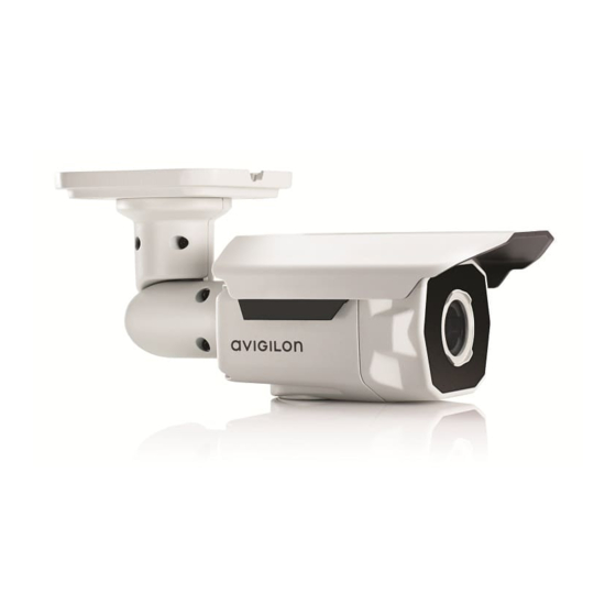
Overview Front View Sun Shroud IR Illuminator Feature Description Sun Shroud An adjustable cover to help protect the lens against glare from the sun. IR Illuminator Provides scene illumination in the IR spectrum. -
Page 12: Bottom View
Bottom View Configuration Panel Connection Status LED Cable Entry Notch Serial Number Tag Configuration SD Card Slot Link LED Ethernet Port Feature Description Configuration Panel Quick access port for configuring the camera during installation. To access the Configuration Panel, remove the plug with the supplied opening tool. -
Page 13: Side View
Side View Sun Shroud Mount Mount Arm Mounting Bracket Adjustment Screws Feature Description Sun Shroud Mount Mounting bracket for the sun shroud. Mount Arm Adjustable mount arm for positioning the camera. Mounting Bracket Allows the camera to be flush mounted or surface mounted. -
Page 14: Installation
Installation Camera Package Contents Ensure the package contains the following: • Avigilon High Definition IP Bullet Camera • T20 TORX tamper resistant key • 4 screws and anchors for solid walls • Drill template sticker • Configuration Panel opening tool Installation Steps Complete the following procedures to install the camera. -
Page 15: Mounting The Camera
If there are external input or output devices that need to be connected to the camera (for example: door contacts, relays, speakers, etc), connect the devices to the camera’s I/O connector cable. For more information, see Connecting to External Devices. Connect power using one of the following methods: •... -
Page 16: Assigning An Ip Address
(Zeroconf) is used to choose an IP address. When the IP address is set using Zeroconf, the IP address is in the 169.254.0.0/16 subnet. The IP address settings can be changed using one of the following methods: • Avigilon Camera Installation Tool software application. • Camera's web browser interface: http://<camera IP address>/ •... -
Page 17: Aiming The Camera
Once satisfied, tighten the adjustment screws on the mount arm to secure the camera’s position. In the Avigilon Camera Installation Tool or camera web browser interface, adjust the camera’s Image and Display settings to achieve the desired zoom position. -
Page 18: (Optional) Configuring Onboard Storage
(Optional) Configuring Onboard Storage To use the camera’s onboard storage feature, you must insert an SD card into the SD card slot. Avigilon offers a line of SD cards that have been fully tested with this camera to ensure optimal SD card performance. -
Page 19: Connecting To External Devices
Connecting to External Devices External devices are connected to the camera through the I/O cable. Refer to the following table for the connections. NOTE: The camera can be connected to an external microphone and speaker through the I/O connector. Table:External I/O Connections Wire Color Description Yellow... -
Page 20: Led Indicators
LED Indicators Once the camera is connected to the network, the Connection Status LED will display the camera’s progress in connecting to the Network Video Management software. The following table describes what the LEDs indicate: Table:LED Indicators Connection Connection Description State Status LED Obtaining IP... -
Page 21: Removing The Sun Shroud
Removing the Sun Shroud The sun shroud is not required when the camera is installed indoors. As you press down on the center of the sun shroud, pull up the corners of the shroud from one side of the camera. Avoid the black tab on the sun shroud mount. -
Page 22: Reset To Factory Default Settings
Reset to Factory Default Settings If the camera no longer functions as expected, you can choose to restore the camera to its factory default settings. Use the firmware revert button to reset the camera. Firmware Revert Button Figure: The firmware revert button in the Configuration Panel. Ensure the camera is powered on. -
Page 23: Setting The Ip Address Through The Arp/Ping Method
Setting the IP Address Through the ARP/Ping Method Complete the following steps to configure the camera to use a specific IP address: Locate and copy down the MAC Address (MAC) listed on the Serial Number Tag for reference. Open a Command Prompt window and enter the following commands: arp -s <New Camera IP Address>... -
Page 24: Specifications
Specifications H3-BO1-IR H3-BO2-IR Camera Audio Input/Output Line level input and output Lens 3-9 mm, F1.2, P-Iris, remote focus 9-22 mm, F1.6, P-Iris, remote focus and zoom and zoom Onboard Storage SD/SDHC/SDXC slot – minimum class 4; class 6 or better recommended Network Network 100Base-TX... -
Page 25: Limited Warranty & Technical Support
This warranty states Avigilon’s entire liability and your exclusive remedy against Avigilon for any failure of this product to operate properly. In no event shall Avigilon be liable for any indirect, incidental, special,...
Need help?
Do you have a question about the 1.0W-H3-BO1-IR and is the answer not in the manual?
Questions and answers