
Related Manuals for Avigilon 29MP-HD-PRO-C


Summary of Contents for Avigilon 29MP-HD-PRO-C
-
Page 1: Installation Guide
Installation Guide Avigilon™ High Definition Professional IP Camera Models: 29MP-HD-PRO-C, 29MP-HD-PRO-M, 16MP-HD-PRO-C, 16MP-HD- PRO-M, 11MP-HD-PRO-C, 11MP-HD-PRO-M, 8MP-HD-PRO-C and 8MP-HD-PRO-M... -
Page 2: Important Safety Information
48 VDC, 13 W min. for models 29MP-HD-PRO-C, 29MP-HD-PRO-M, 16MP-HD-PRO-C, 16MP-HD-PRO- M, 8MP-HD-PRO-C and 8MP-HD-PRO-M. Any external power supply connected to this product may only be connected to another Avigilon product of the same model series. External power connections must be properly insulated. -
Page 3: Regulatory Notices
Changes or modifications made to this equipment not expressly approved by Avigilon Corporation or parties authorized by Avigilon Corporation could void the user’s authority to operate this equipment. - Page 4 © 2010 - 2015, Avigilon Corporation. All rights reserved. AVIGILON, the AVIGILON logo, and AVIGILON CONTROL CENTER are trademarks of Avigilon Corporation. Other product names mentioned herein may be the trademarks of their respective owners. The absence of the symbols ™ and ® in proximity to each trademark in this product or its packaging is not a disclaimer of ownership of the related trademark.
-
Page 5: Table Of Contents
Table of Contents Overview Rear View Front View Installation Required Tools and Materials Camera Package Contents Installation Steps Mounting the Lens Mounting the Camera Connecting External Power Aiming and Focusing the Camera Connecting to the Network Video Recorder IP Address Selection Connecting to External Devices LED Indicators Resetting to Factory Default Settings... -
Page 6: Overview
Overview Rear View 1. Connection Status LED Provides information about device operation. For more information, see LED Indicators on page 8 2. I/O Connector Block Provides connections to external input/output devices. 3. Power Connector Block Accepts a terminal block with either an AC or DC power connection. DC input can be either polarity. Only required when Power over Ethernet is not available. -
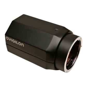
Page 7: Front View
Front View 1. Camera Mounts Provides mounting points for the camera. Mounts accept 1/4”-20 UNC bolts commonly found on tripods and mounting brackets. 2. Lens Mount Accepts EF and EF-S lenses. 3. Lens Release Button Releases the lens that is mounted on the camera. Front View... -
Page 8: Installation
To avoid poor image quality caused by incorrect lens selection, only use lenses that are recommended by Avigilon for use with this camera model. For a list of lenses recommended for use with this camera model, contact your Avigilon dealer or representative. -
Page 9: Mounting The Camera
To detach a lens, complete the following steps: 1. While pressing the lens release button, turn the lens counterclockwise until it stops. 2. Remove the lens from the camera.Immediately mount another lens or a dust cap on the lens mount to prevent contamination. -
Page 10: Aiming And Focusing The Camera
1. If available, adjust the zoom using the appropriate ring on the lens. 2. If the lens has an auto focus (AF) mode, set the lens switch to the AF position to allow the Avigilon Control Center software to control the camera’s focus. -
Page 11: Ip Address Selection
If this fails, an IP address will be selected using Zeroconf (APIPA). If the IP address is set using Zeroconf, the IP address will be in the 169.254.* subnet. A static IP address can be set from the Avigilon Control Center software, consult the software user guide for details. - Page 12 6. Output B — The output uses a photocoupler and is electrically isolated from the internal circuitry. The output terminal (A and B) connections can be made with either polarity. The output can drive a maximum load of 50 V and 120 mA. 7.
-
Page 13: Led Indicators
LED Indicators Once connected to the network, the Connection Status LED will display the progress in connecting to the Network Video Management software. The following table describes what the LEDs indicate: Connection Status Connection State Description One short flash every Obtaining IP Address Attempting to obtain an IP address. -
Page 14: Resetting To Factory Default Settings
Resetting to Factory Default Settings If the camera no longer functions as expected, you can choose to reset the camera to its factory default settings. Use the firmware revert button to reset the camera. Figure 1: Firmware revert button on the rear of the camera. 1. -
Page 15: Cleaning
Cleaning Image Sensor The image sensor is protected from contamination by protective glass. However, the protective glass can be contaminated by dust and other debris. To clean the protective glass, perform the following steps: 1. Remove the lens or dust cap. 2. -
Page 16: Specifications
Specifications Network Network 100Base-TX Cabling Type CAT5 Connector RJ-45 Security Protocols UDP, TCP, SOAP, DHCP, Zeroconf Mechanical Dimensions 1120 mm x 79 mm x 74 mm (4.7” x 3.1” x 2.9”) L x W x H Weight 1.15 kg (2.5 lbs) without lens Camera Mount ¼”-20 UNC (top and bottom) Electrical... - Page 17 EN 55024 EN 61000-4-2 EN 61000-4-3 Electromagnetic EN 61000-4-4 Immunity EN 61000-4-5 EN 61000-4-6 EN 61000-4-11 EN 61000-6-1 Specifications...
-
Page 18: Limited Warranty & Technical Support
Limited Warranty & Technical Support Avigilon warrants to the original consumer purchaser, that this product will be free of defects in material and workmanship for a period of 3 years from date of purchase. The manufacturer’s liability hereunder is limited to replacement of the product, repair of the product or replacement of the product with repaired product at the discretion of the manufacturer.
Need help?
Do you have a question about the 29MP-HD-PRO-C and is the answer not in the manual?
Questions and answers