Table of Contents
Advertisement
Advertisement
Table of Contents

Related Manuals for Black Box ServSwitch Octet KV1700


Summary of Contents for Black Box ServSwitch Octet KV1700
- Page 1 DECEMBER 2005 KV1700 KV1701 KV1702 KV1703 KV1711 KV1712 KV1713...
- Page 3 ™ The ServSwitch family from BLACK BOX—the one-stop answer for all your KVM switching needs! This manual will tell you all about your new ServSwitch Octet, including how to install, operate, and troubleshoot it. For an introduction to the ServSwitch Octet, see Chapter 2.
- Page 4 SERVSWITCH OCTET INSTALLER/USER GUIDE FEDERAL COMMUNICATIONS COMMISSION AND INDUSTRY CANADA RADIO-FREQUENCY INTERFERENCE STATEMENTS This equipment generates, uses, and can radiate radio-frequency energy and if not installed and used properly, that is, in strict accordance with the manufacturer’s instructions, may cause interference to radio communication. It has been tested and found to comply with the limits for a Class A computing device in accordance with the specifications in Subpart B of Part 15 of FCC rules, which are designed to provide reasonable protection against such interference when the equipment is operated in a...
- Page 5 Canada (cUL, ICES-003) European Union (CE) TRADEMARKS USED IN THIS MANUAL BLACK BOX® and the logo are registered trademarks, and ServSwitch, ServSelect, and ServSelect IP are trademarks of BLACK BOX Corporation. Apple, Mac, and Macintosh are registered trademarks of Apple Computer, Inc.
- Page 6 SERVSWITCH OCTET INSTALLER/USER GUIDE Normas Oficiales Mexicanas (NOM) Electrical Safety Statement INSTRUCCIONES DE SEGURIDAD Todas las instrucciones de seguridad y operación deberán ser leídas antes de que el aparato eléctrico sea operado. Las instrucciones de seguridad y operación deberán ser guardadas para referencia futura.
- Page 7 NOM STATEMENT El aparato ha sido expuesto a la lluvia; o D: El aparato parece no operar normalmente o muestra un cambio en su desempeño; o El aparato ha sido tirado o su cubierta ha sido dañada.
- Page 8 SERVSWITCH OCTET INSTALLER/USER GUIDE...
-
Page 9: Table Of Contents
Troubleshooting ........75 Calling Black Box....... 75... - Page 10 SERVSWITCH OCTET INSTALLER/USER GUIDE...
-
Page 11: Specifications
CHAPTER 1: SPECIFICATIONS 1. Specifications During the course of this product’s lifetime, modifications might be made to its hardware or firmware that could cause these specifications to change without notice. Octet KV1700 Product Specifications Agency Approvals EN55022 Class A, EN55024, EN61000-3-2, EN61000-3-3, EN60950, FCC47CFR Part 15 Class A, CSA C22.2 No. - Page 12 SERVSWITCH OCTET INSTALLER/USER GUIDE Octet KV1701 Product Specifications Agency Approvals EN55022 Class A, EN55024, EN61000-3-2, EN61000-3-3, EN60950, FCC47CFR Part 15 Class A, CSA C22.2 No. 60950, IEC 60950, FCC Class A, UL 60950 third edition, VCCI Class A Mechanical Height: 1U Width: 17”...
- Page 13 CHAPTER 1: SPECIFICATIONS Octet KV1702 Product Specifications Agency Approvals EN55022 Class A, EN55024, EN61000-3-2, EN61000-3-3, EN60950, FCC47CFR Part 15 Class A, CSA C22.2 No. 60950, IEC 60950, FCC Class A, UL 60950 third edition, VCCI Class A Mechanical Height: 2 U Width: 17”...
- Page 14 SERVSWITCH OCTET INSTALLER/USER GUIDE Octet KV1703 Product Specifications Agency Approvals EN55022 Class A, EN55024, EN61000-3-2, EN61000-3-3, EN60950, FCC47CFR Part 15 Class A, CSA C22.2 No. 60950, IEC 60950, FCC Class A, UL 60950 third edition, VCCI Class A Mechanical Height: 1 U Width: 17”...
-
Page 15: Product Specifications
CHAPTER 1: SPECIFICATIONS Octet (KV1711, KV1712, KV1713) User Station Product Specifications Agency Approvals EN55022 Class A, EN55024, EN61000-3-2, EN61000-3-3, EN60950, FCC47CFR Part 15 Class A, CSA C22.2 No. 60950, IEC 60950, FCC Class A, UL 60950 third edition, VCCI Class A Mechanical Height: 1U Width: 10.98”... - Page 16 SERVSWITCH OCTET INSTALLER/USER GUIDE Octet (KV1711, KV1712, KV1713) User Station Product Specifications (Continued) KV1711 and KV1712 Peripherals: PS/2 keyboard and mouse, Sun keyboard and mouse KV1713 Peripherals: PS/2 keyboard and mouse, USB keyboard and mouse Supported Hardware Video resolution: 1024 x 768 (1280 x 1024 KV1712 and KV1713 only) with 1,000 feet of UTP from server to user, 1280 x 1024 with 500 feet of UTP from server to user;1600 x 1200 with 100 feet of UTP from server to user...
- Page 17 CHAPTER 1: SPECIFICATIONS Octet SAM (KV1720, KV1721, KV1722) Product Specifications (Continued) Input ports for KV1721A: 1 USB keyboard and mouse (supports Intel, Sun, Macintosh), 1 15HDD male, VGA video Ports Input ports for KV1722A: 1 8-pin miniDIN, Sun keyboard and mouse, 1 15HDD male, VGA video, 1 Sun HwB or HDB15 adapter Output ports: 1 RJ45 Octet interconnect Server Ports...
- Page 18 SERVSWITCH OCTET INSTALLER/USER GUIDE Octet Serial SAM (KV1724) Product Specifications (Continued) AC input power: 6 VDC maximum Environmental/Power Operating Temperature: 50º F-104º F; 10º C-40º C Storage Temperature: -4º F-140º F; -20º C-60º C Humidity: 10-95% non-condensing operating Serial Ports Type: DCE Emulation: VT100 Baud Rate: 115200, 57600, 38400, 19200, 9600,...
- Page 19 CHAPTER 1: SPECIFICATIONS Octet SAMDM (KV1725, KV1726, KV1727) Product Specifications Environmental/Power Power consumption: 130 mA Humidity: 10-95% non-condensing Operating temperature: 32°-122° F; 10° C-50° C Storage temperature: 4° F-140° F; -20° C-60° C Power supply: 5 VDC Ports Input ports for KV1725A: 1 6-pin miniDIN, PS/2 keyboard and mouse;...
- Page 20 SERVSWITCH OCTET INSTALLER/USER GUIDE...
-
Page 21: Introduction
An Octet switching system may consist of one or more rack mountable Octet switches and other cascaded KVM switches, the Black Box matrix user station and the Black Box SAM (Server Access Module). The Octet switch is equipped with the Black Box On-Screen Display (OSD), allowing you to use your keyboard or mouse to select any attached server or serial device. - Page 22 The Octet switching system enables users to connect to servers attached to Black Box switches cascaded below the Octet switch through its local port. The table below lists both Black Box and non-Black Box KVM switches that can be seamlessly cascaded in an Octet switching system.
-
Page 23: Component Overview
For additional flexibility, you can attach other Black Box KVM switches to the Octet switching system as well. Refer to Chapter 3 for additional information on cascading an Octet switching system. - Page 24 SERVSWITCH OCTET INSTALLER/USER GUIDE compensation for video degradation. The Octet user station is housed in a desktop mounting unit that may also act as a monitor stand. The Octet KV1711, KV1712 and KV1713 user stations provide two RJ45 ports, enabling the connection of one Octet switch and one or two Octet SAMs.
-
Page 25: Utp Cables
To avoid potentially fatal shock hazard and possible damage to equipment, please observe the following precautions: • Do not use a 2-wire extension cord in any Black Box product configuration. • Test AC outlets at the server and monitor for proper polarity and grounding. - Page 26 SERVSWITCH OCTET INSTALLER/USER GUIDE • Reduced Air Flow: Installation of the equipment in a rack should be such that the amount of airflow required for safe operation of the equipment is not compromised. • Mechanical Loading: Mounting of the equipment in the rack should be such that a hazardous condition is not achieved due to uneven mechanical loading.
-
Page 27: Installation
Optionally you may need: • Octoware software available on the included CD and through download from Black Box 3.2 Installing an Octet Switching System Figure 3.1 illustrates one possible configuration for your Octet switch. Follow the detailed set of procedures following Figure 3.1 to install the Octet switching system. - Page 28 SERVSWITCH OCTET INSTALLER/USER GUIDE Octet Switch Serial SAM Octet User Station Local PC Figure 3-1. Basic Octet Switching System Configuration CAUTION: Power Considerations: To reduce the risk of electric shock or damage to your equipment - - Do not disable the power cord grounding plug. The grounding plug is an important safety feature. - Plug the power cord into a grounded (earthed) outlet that is easily accessible at all times.
-
Page 29: Installing An Octet Switch
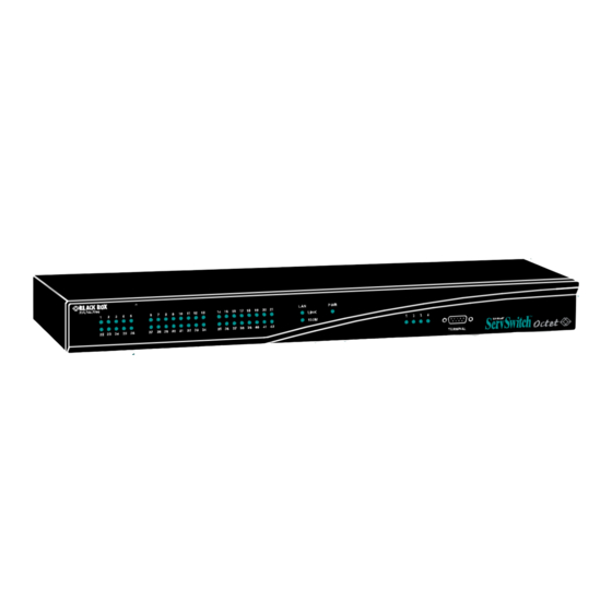
CHAPTER 3: INSTALLATION 3.3 Installing an Octet Switch The Octet switch is the central hub of your Octet switching system. All users and computers are connected through it. Figure 3-2. Octet KV1700 Switch Figure 3-3. Octet KV1701 Switch Figure 3-4. Octet KV1702 Switch Figure 3-5. - Page 30 SERVSWITCH OCTET INSTALLER/USER GUIDE A rackmounting kit is supplied with each Octet switch. Before installing the switch and other components in the rack, plan carefully to avoid uneven loading or overloading of the rack. CAUTION: Rack Loading To reduce the risk of electric shock or damage to your equipment- - Do not disable the power cord grounding plug.
- Page 31 CHAPTER 3: INSTALLATION To install the rack mounting bracket: Remove the two side screws closest to the front from each side of your Octet switch. Line up the holes in the brackets with the holes on the sides of the Octet switch. Using the screws supplied with the rack mounting bracket, thread one through each of the holes in the sides of the rack mount brackets and into the Octet switch.
- Page 32 SERVSWITCH OCTET INSTALLER/USER GUIDE To make a LAN connection: Using a UTP cable, connect the Network port on the back of the Octet switch to your LAN. Connecting devices to the Octet switch Once the Octet switch is installed, you can begin attaching servers or serial devices to it. All are connected to the Octet switch through the use of Octet SAMs.
- Page 33 CHAPTER 3: INSTALLATION Terminal Port Server Ports Network Port User Ports Figure 3-10. Octet KV1702 Switch Rear Panel Server Ports Network Port User Ports Figure 3-11. Octet KV1703 Switch Rear Panel To connect servers to the Octet switching system: Locate the SAM appropriate to the server you wish to attach. Plug the SAM connectors into the appropriate ports on the back of the selected server.
-
Page 34: Connecting Users To The Octet Switching System
SERVSWITCH OCTET INSTALLER/USER GUIDE Attach one end of the CAT 5 cable to the RJ45 connector on the Serial SAM. Connect the other end of the CAT 5 cable to the desired computer port on the back of your Octet switch. Connect the power supply to the power connector on your Serial SAM. - Page 35 CHAPTER 3: INSTALLATION Connections to Octet Switch/Local Server Multimedia Serial Port AC Power Monitor Access Figure 3-14. Octet KV1713 User Station Rear Panel To connect users to the Octet switching system: Place the Octet user station near the monitor you wish to connect. Each unit is designed to bear the weight of a monitor and can be used as a monitor stand.
-
Page 36: Installing A Kv1713 User Station And Samdm Module For Audio And Serial
SERVSWITCH OCTET INSTALLER/USER GUIDE Connect one end of a UTP cable into the RJ45 port on your SAM or Serial SAM. Route the cable to your Octet user station and connect the other end to the RJ45 server port. Check the unique identifier (UID) on the back of the SAM and log it for future use. -
Page 37: Connecting A Samdm Module For Dual Port Output
CHAPTER 3: INSTALLATION To install an KV1713 user station and SAMDM module: Power down your systems. Attach one end of an appropriate power cord to your Octet switch. Plug the other end into an appropriate AC wall outlet. Repeat this pro- cedure for the KV1713 user station. -
Page 38: Installing A Cascaded Octet Switching System
SERVSWITCH OCTET INSTALLER/USER GUIDE Octet Switch SAMDM Module Server Octet Switch Figure 3.16: SAMDM Module Dual Port Connectivity To connect a SAMDM module for dual port output: Power down the server. Connect a SAMDM module VGA monitor, keyboard and mouse connectors into the appropriate ports on the back of the server. - Page 39 CHAPTER 3: INSTALLATION KV1702 KV1711 User Station KV1701 KV1701 KV1701 KV1701 Servers Servers Servers Servers KV1701 KV1701 Servers Servers Figure 3-17. Cascaded Octet Switching System To install a cascaded Octet switching system: Position the Octet switches that will be connected and select a switch to be the primary hub.
-
Page 40: Synchronizing The System With Octoware
OCTET INSTALLER/USER GUIDE NOTE: The Octet switch can be used with non-Black Box KVM switches. Switching to a port with an attached non- Black Box KVM switch requires the use of the OSD of the non-Black Box unit to continue the switch. -
Page 41: Basic Operations
CHAPTER 4: BASIC OPERATIONS 4. Basic Operations CHAPTER 4.1 Power Up and LEDs Octet switch There are three groups of LEDs on the front panel of your Octet KV170x switch. Each green LED in the left group corresponds to a server port. Each LED illuminates when the system or cascaded Octet switch is attached and powered up. -
Page 42: Osd Overview
Serial SAM loses power. 4.2 OSD Overview The Octet user station uses the Black Box OSD, featuring intuitive menus to configure your system and select devices. The OSD is easily accessed and always available at the desktop. - Page 43 CHAPTER 4: BASIC OPERATIONS OSD Navigation Buttons Displays the last subscreen in the hierarchy Target The Target tab lists the servers that may be accessed from your Octet user station and the available modes for these servers. Servers may be selected in Shared, Private, Scan or Maintain modes.
- Page 44 SERVSWITCH OCTET INSTALLER/USER GUIDE NOTE: Switching from a silent to an audio source that is set at high volume may harm your hearing. When the Octet user station is powered, you are prompted for your password. Passwords must be at least six characters long. NOTE: All ASCII characters can be used in the login prompt.
- Page 45 CHAPTER 4: BASIC OPERATIONS NOTE: Should you lose your password, please contact Black Box Technical Support for assistance. (Optional) Change the scan dwell time by typing a number between 3 and 99. Click Apply. Click Cancel to exit the OSD.
- Page 46 SERVSWITCH OCTET INSTALLER/USER GUIDE Figure 4-4. OSD Target Flag: Set Position 11. Move the target flag by dragging and dropping the title bar to a desired position. 12. After placing the target flag in the desired position, click the X button to set the posi- tion and return to the Target Flag screen.
- Page 47 CHAPTER 4: BASIC OPERATIONS Figure 4-6. OSD Change Hotkey Click the down arrow button and select the desired hotkey from the drop-down list. Click OK. NOTE: If the selected hotkey is already assigned to a different server, you can re-assign the selected hotkey or return to the Change Hotkey screen to select another hotkey.
-
Page 48: Selecting Servers
SERVSWITCH OCTET INSTALLER/USER GUIDE OSD hotkey sequence and then access the OSD by pressing either the left or right Ctrl key twice. The available OSD hotkey sequences are: Scroll Lock+Scroll Lock Print Screen Ctrl+Ctrl (L-R) Ctrl+Ctrl (L) Ctrl+Ctrl (R) Alt+Alt (L-R) Shift+Shift (L-R) Shift+Shift (L) Shift+Shift (R) - Page 49 CHAPTER 4: BASIC OPERATIONS To select a server: Press Ctrl+Ctrl to launch the OSD. Click the Target tab and select the appropriate access mode: Shared, Private, Scan or Maintain. Double-click the server name. -or- Click the server name and then click the Start button. To disconnect from a selected server, activate the OSD and click the Clear button or switch to another server.
-
Page 50: Keyboard Translation
SERVSWITCH OCTET INSTALLER/USER GUIDE 4.4 Keyboard Translation The Octet user station allows you to use PS/2 and Sun keyboards to operate any type of attached computer. However, when crossing platforms, certain keys will need to be remapped in order to provide all of the functions available on the keyboard native to that platform. - Page 51 CHAPTER 4: BASIC OPERATIONS Power/Sleep for USB Computers (Continued) Power Enabled Win 98/2000 Power Enabled Win 98/Mac To issue the Power/Sleep command: Enable the Scroll Lock Mode and press F11 (or the Sleep key) on a PS/2 keyboard. -or- For a Sun computer, press the Power key.
- Page 52 SERVSWITCH OCTET INSTALLER/USER GUIDE...
-
Page 53: Advanced Operations
CHAPTER 5: ADVANCED OPERATIONS 5. Advanced Operations 5.1 User Maintenance The Octet switching system can be configured to support up to 128 users. Each user is identified by a unique name and password and can be assigned full, view only or no rights to servers attached to the Octet switch. - Page 54 SERVSWITCH OCTET INSTALLER/USER GUIDE Figure 5-2. Octet OSD Add User Enter the name of the user in the Username field. Enter the user’s password and confirm it in the provided fields. Click OK. To edit a user: Press Ctrl+Ctrl to launch the Octet OSD. Click the Admin tab.
- Page 55 CHAPTER 5: ADVANCED OPERATIONS To force user login: Press Ctrl+Ctrl to launch the Octet OSD. Click the Admin tab. Click the down arrow to display the User Admin screen. Select admin from the list and click the Edit user button. The Edit User screen displays. If a password has not yet been assigned to admin, create one now by typing a password in the Password and Confirm Password fields.
-
Page 56: Device Maintenance
SERVSWITCH OCTET INSTALLER/USER GUIDE targets from the list of available servers that you wish to be controlled externally. Select the appropriate access level: none, view or full. NOTE: User rights must be assigned to each MDM SAM and MDM server. After configuring all servers, click the OK button. - Page 57 CHAPTER 5: ADVANCED OPERATIONS Figure 5-6. Octet OSD Edit Device The UID and Type fields are not editable. The Type field displays the type of device being edited, including one of the following: • PS/2 Single-Port • SUN Single-Port • USB Single-Port •...
- Page 58 Click the Edit Device button. The Edit Device screen displays. Type a new name (1-15 characters) for the device in the Name field. From the Target drop-down list, select the cascaded Black Box KVM switch to which the Octet SAM is attached.
- Page 59 CHAPTER 5: ADVANCED OPERATIONS A list of devices will display. In the Find field, click name to search by name. - or - Click UID to search by UID. NOTE: If a name has never been set for the device, a default name will be displayed. Clicking the Reset name button sets the device name back to its default.
-
Page 60: Console Maintenance
SERVSWITCH OCTET INSTALLER/USER GUIDE Select the Octet SAM for which you wish to view version, configuration and connection information. Click the Edit device button. The Edit Device screen displays. Click the Info button. The Information screen displays. Figure 5-8. Octet OSD Information: Octet SAM Click Close to return to the Device Admin screen. - Page 61 CHAPTER 5: ADVANCED OPERATIONS Figure 5-9. Octet OSD Status Click the double arrow navigation button to display the Configure screen. Figure 5-10. Octet OSD Configure The Keyboard Layout field displays the current keyboard layout. Click the double arrow button to scroll through and select the desired option. The Keyboard Type field is activated if your Octet switching system includes an Octet KV1712 or above user station connected to a PS/2 keyboard.
- Page 62 SERVSWITCH OCTET INSTALLER/USER GUIDE NOTE: Standard refers to any keyboard. If your Octet user station is connected to a Pinnacle FAK, you must select Pinnacle FAK in the Type field to enable support for this keyboard. Click Apply to apply and save changes. (Optional) Change the OSD hotkey sequence.
-
Page 63: Forcing An External Switch
CHAPTER 5: ADVANCED OPERATIONS Click the Console tab. Click the down arrow to display the Configure screen. Under Lockdown, click User to prevent changes to the User tab. - and/or - Click Console to prevent changes to the console data. Click Apply to apply and save changes. -
Page 64: Osd Command Line Operations
SERVSWITCH OCTET INSTALLER/USER GUIDE which the SNMP user has access. For instructions on adding an SNMP user, see To add a user in this chapter. OSD Command Line operations The OSD Command Line enables you to enter commands to reset the mouse and keyboard, force a user at another user station to make and/or break a connection and configure the Direct Digital Control (DDC) table used by the Octet SAM. - Page 65 CHAPTER 5: ADVANCED OPERATIONS Type fd ‘[TargetUserStationName]’ and press Enter to force the target user station to disconnect from the connected server. NOTE: The TargetUserStationName is shown in the Octet OSD ? tab of the target user station. After selecting the ? tab, press the key to view the unit name at the bottom of the tab.
- Page 66 SERVSWITCH OCTET INSTALLER/USER GUIDE...
-
Page 67: Terminal Operations
CHAPTER 6: TERMINAL OPERATIONS 6. Terminal Operations 6.1 Accessing the Terminal Menu Each Octet KV170x switch can be configured at the unit level through the Terminal port. All terminal commands are accessed through a terminal or PC running terminal emulation software. -
Page 68: To Change The Password
This password places your Octet switch terminal in a secure mode. This password should be guarded like any network password and care should be taken to avoid forgetting or misplacing it. Should you lose your password, please contact Black Box Technical Support for assistance. Exit... -
Page 69: Serial Sam
CHAPTER 7: SERIAL SAM 7. Serial SAM The Serial SAM is a serial-to-VGA converter which permits VT100-capable devices to be viewed from the Octet switch local port. The actual serial data is not accessed, but is merely displayed. All serial data coming from the target device is displayed in a VT100 window, placed into a video buffer and sent to the Octet switch as though it came from a VGA server. - Page 70 SERVSWITCH OCTET INSTALLER/USER GUIDE • Background: This option changes the screen’s background color. The currently- selected color displays in the option line as it is changed. Available colors are Black, Grey, Light Grey, White, Yellow, Green, Teal, Cyan, Blue, Dark Blue, Purple, Pink, Orange Red, Maroon and Brown.
- Page 71 CHAPTER 7: SERIAL SAM Press Enter to save your changes and exit the Configuration Screen. - or - Press Esc to exit the Configuration Screen without saving the changes. Creating an Serial SAM macro Pressing the Page Down key when the Configuration Screen is displayed will provide access to the Macro Configuration screen.
- Page 72 SERVSWITCH OCTET INSTALLER/USER GUIDE Press each key to perform the action described in the following table.. History Mode Control Keys History Mode Action Home Move to the top of the buffer. Move to the bottom of the buffer. Page Up Move up one buffer page.
-
Page 73: Language Support
CHAPTER 7: SERIAL SAM Serial SAM Pinouts (Continued) Host Signal DB9-F Signal Flow SRL Signal Name/Description Name/Description CTS - Clear to Send Out of SRL RTS - Request to Send N/C - Not Connected N/C - Not Connected Language support The Serial SAM is designed to operate correctly with all of the keyboard layouts that are selectable on the Octet KV170x switch. - Page 74 SERVSWITCH OCTET INSTALLER/USER GUIDE...
-
Page 75: Edit Device Screen Settings
CHAPTER 8: EDIT DEVICE SCREEN SETTINGS 8. Edit Device Screen Settings KV2016 Switch Edit Device Screen Settings Target KV2016 switch Ports The Print Screen key is not operational for a Hotkeys server connection Required: Setting the display order of the server Unit Settings list to “Port”... -
Page 76: Kvm Switch
SERVSWITCH OCTET INSTALLER/USER GUIDE KVM Switch Edit Device Screen Settings Target KVM switch Ports 1, 2, 4, 8, 12, 16, 20, 24, 28, 32 Ctrl–Ctrl (L), Ctrl–Ctrl (R), Ctrl–Ctrl (L-R) Alt–Alt (L), Alt–Alt (R), Alt–Alt (L-R) Shift–Shift (L), Shift–Shift (R), Shift–Shift (L-R) Print Screen Hotkeys Scroll, Scroll–Scroll... -
Page 77: Troubleshooting
It ccontains no user-serviceable parts. Refer to the table on the following page for Black Box Technical Support Information: Before contacting Black Box Technical Support, make a record of the history of the problem. We will be able to provide more efficient and accurate assistance if you have a complete description, including: •... - Page 78 SERVSWITCH OCTET INSTALLER/USER GUIDE Black Box Technical Support Country Web Site/E-Mail Phone www.blackbox.com 724-746-5500 724-746-0746 info@blackbox.com www.black-box.at +43 1 256 98 56 +43 1 256 98 56 Austria support@black-box.at Belgium www.blackbox.be +32 2 725 85 50 +32 2 725 92 12 support.nederlands@blackbox.be...
- Page 80 Customer Support Information: For FREE Technical Support 24 hours a day, 7 days a week, call 724-746-5500 or fax 724-746-0746 Mailing address: Black Box Corporation, 1000 Park Dr., Lawrence, PA 15055-1018 World-Wide Web: www.blackbox.com • Email: info@blackbox.com © Copyright 2005. Black Box Corporation. All rights reserved.
Need help?
Do you have a question about the ServSwitch Octet KV1700 and is the answer not in the manual?
Questions and answers