3Com 6000 series Getting Started Manual
Hide thumbs
Also See for 6000 series:
- Installation manual (82 pages) ,
- Command reference manual (838 pages) ,
- Module manual (187 pages)

Related Manuals for 3Com 6000 series


Summary of Contents for 3Com 6000 series
- Page 1 ® 3Com Router 6000 Family Getting Started Guide www.3Com.com/ Part Number 10015123 Rev. AB Published September 2007 Mfg. BOM 3122A077...
- Page 2 All other company and product names may be trademarks of the respective companies with which they are associated. ENVIRONMENTAL STATEMENT It is the policy of 3Com Corporation to be environmentally friendly in all operations. To uphold our policy, we are committed to: Establishing environmental performance standards that comply with national legislation and regulations.
- Page 3 ® for your 3Com Router Thank you for purchasing a 3Com Router 6000 Family router. As part of our commitment to bringing you the most capable and dependable network equipment, 3Com offers free software maintenance updates and documentation updates on our website.
-
Page 5: Table Of Contents
Contents Contents Download the latest software and documentation for your 3Com® Router Contents About This Guide Before You Start Release Notes Conventions Related Documentation Documentation Comments Introducing the Router 6000 Family About the Router 6000 3Com Router 6040 3Com Router 6080... - Page 6 Backing Up/Restoring the Extended Segment of the Boot ROM Image Upgrading the Application Image Using TFTP Dealing with a Router Password Loss Obtaining Support for Your 3Com Products Register Your Product to Gain Service Benefits Solve Problems Online Purchase Extended Warranty and Professional Services...
-
Page 7: About This Guide
If the information in the release notes differ from the information in this guide, follow the instructions in the release notes. Most user guides and release notes are available in Adobe Acrobat Portable Document Format (PDF) or HTML on the 3Com Web site: www.3Com.com... -
Page 8: Conventions
This manual describes the various modules that are available for use with the Router 5000 and Router 6000. Release Notes ■ These notes provide information about the current software release, including new features, modifications, and known problems. The release notes are supplied on the 3Com Web site. -
Page 9: Documentation Comments
Part Number 10015123 rev. AA Page 21 Please note that we can only respond to comments and questions about 3Com product documentation at this e-mail address. Questions related to technical support or sales should be directed in the first instance to your network supplier. - Page 10 10 About This Guide...
-
Page 11: Introducing The Router 6000 Family
■ The PSU Module ■ About the The 3Com Router 6000 Family are high-performance edge routers that Router 6000 support flexible interface cards (FICs), hot swappable fan modules, and power supply units (PSUs) in 1+1 redundancy. Abundant FIC options Abundant flexible interface cards (FICs) are available for the Router 6000 allowing great flexibility and investment protection. - Page 12 12 Chapter 1: Introducing the Router 6000 Family 6000 can be installed with an ATM cards to connect its network to an ATM network. MPLS Multiprotocol label switching (MPLS), a combination of IP and ATM technologies, can provides faster forwarding speed and get support from IP protocols to accommodate to emerging applications.
-
Page 13: 3Com Router 6040
3Com Router 6040 13 3Com Router 6040 Figure 1 Front panel of the 3Com Router 6040 1) Slot0 for the main control board 2) FIC Slot1 3) FIC Slot2 4) FIC Slot3 5) FIC Slot4 6) ESD-preventive wrist strap port... -
Page 14: 3Com Router 6080
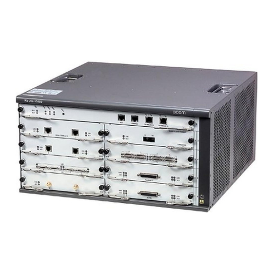
14 Chapter 1: Introducing the Router 6000 Family 3Com Router 6080 Figure 3 Front panel of the 3Com Router 6080 (10) (11) 1) Handles 2) Slot0 for the main control board 3) FIC Slot1 4) FIC Slot2 5) FIC Slot3... -
Page 15: System Description
System Description 15 System Description Table 1 System description of the 3Com Router 6040/6080 Item 3Com Router 6040 3Com Router 6080 FIC slot Dimensions (H x W x D) 130.5 x 436.2 x 420 mm 219.5 x 436.2 x 420 mm (5.1 x 17.2 x 16.5 in.) -
Page 16: The Rpu Module
16 Chapter 1: Introducing the Router 6000 Family The RPU Module Figure 5 The RPU Your Router 6000 may have one of two different Router Process Units: and RPU or and RPU2. For information on the RPU2, refer to “The RPU2 Module”. - Page 17 The RPU Module 17 Indicators and Button Figure 6 Front panel of the RPU Table 3 RPU Indicator LEDs and button LED and Button Description RUN (green) System operating LED. Blinking means CPU is in normal operation; steady ON or OFF means CPU has failed. Steady ON means the FAN module is operating normally.
-
Page 18: The Rpu2 Module
18 Chapter 1: Introducing the Router 6000 Family The RPU2 Module Figure 7 The RPU2 Your Router 6000 may have one of two different Router Process Units: and RPU or and RPU2. For information on the RPU, refer to “The RPU Module”. - Page 19 The RPU2 Module 19 Indicators and Button Figure 8 Front panel of RPU2 Table 5 RPU2 LEDs and the button LED and button Description RUN (green) System operating LED. Blinking means CPU is in normal operation; steady ON or OFF means CPU has failed. Steady ON means the FAN module is operating normally.
-
Page 20: Encryption Accelerator Daughter Card
20 Chapter 1: Introducing the Router 6000 Family Encryption The RPU2 supports the Encryption Accelerator daughter card. This Accelerator Daughter optional add-on for the RPU2 uses hardware encryption to expedite IP Card packet encryption and provides support for IPSec and DVPN. The PSU Module The power supply system of the Router 6000 can work in either single-power or dual-power mode. -
Page 21: Fan Module
The speed of the fans is controlled by the RPU or RPU2 to maintain optimum system temperature. If a fan stops working, the RPU or RPU2 will display an alarm. The following figure shows a FAN module, using the 3Com Router 6080 as an example. Figure 10 FAN module (Router 6080 shown) -
Page 22: Auto Detect
22 Chapter 1: Introducing the Router 6000 Family Auto-config is well suited to the low-end and mid-range routers on the edge of enterprise networks. To build up a network for configuring your router automatically and remotely, connect the router to the router at the network center depending on the specific interface that you use: For an E1, T1, E3, and T3 interface, use the fiber-optic line of PDH/SDH ■... -
Page 23: Installation
Family. For more information on the cabinets and their installation refer to the chapter “Installing the B68 Cabinet”. Rack-Mounting the The 3Com Router 6000 is designed to fit 19-inch standard racks. The Router following table describes their dimensions: Table 7 Dimensions of the 3Com 6000 Routers... -
Page 24: Mounting The Router On A Tabletop
24 Chapter 2: Installation Mounting the When mounting the router on a tabletop, ensure that the surface is clean Router on a and you have considered the following: Tabletop The table is sturdy and well grounded. ■ 10 cm (3.9 in.) clearance is available around the sides of the chassis for ■... -
Page 25: Ac-Input Power Cord
Power Cords, Grounds and Cables 25 Figure 13 PGND screw on the chassis 1) Grounding screw Connect the PGND to the earth ground using a PGND cable with a grounding resistance less than 5-ohm. If you install the chassis in a 19-inch standard rack, you must also ground the rack. -
Page 26: Console Terminal Cable
26 Chapter 2: Installation AC power socket (recommended) You are recommended to use a three-terminal single-phase power socket with ground contact, which must be grounded reliably. Normally, the ground contact of the power supply system in a building was buried during construction and cabling. - Page 27 Router to LAN Connection 27 The RPU2 provides three 10/100/1000 Mbps Ethernet interfaces, where two are electrical and one provides both fiber-optic and electrical connectors. When both electrical and optical connections are available, you can use only one at a time. For the available SFP options and the interface attributes, refer “The RPU2 Module”.
-
Page 28: Router To Wan Connection
28 Chapter 2: Installation SFPs are optional. They are provided only when ordered. Router to WAN Many types of WAN interfaces are available with the Router 6000 and the Connection one provided by the main control boards is an AUX interface. The following subsections describe how to connect it. -
Page 29: Starting And Configuring The Router 6000
Setting up a Configuration Environment 29 3 Starting and Configuring the Router 6000 Setting up a Connecting the router to a console terminal Configuration To set up a local configuration environment, connect the RJ-45 connector Environment of the console cable to the console port on the router, and the DB-9 connector to the serial port on the console terminal, a PC for example, as shown in Figure 18. - Page 30 30 Chapter 3: Starting and Configuring the Router 6000 Figure 19 Set up a new connection 2 Enter the name of the new connection in the Name field and click <OK>. The dialog box, as shown in Figure 20, appears. 3 Select the serial port to be used from the Connect Using drop-down menu.
- Page 31 Setting up a Configuration Environment 31 Figure 20 Set the connection port 4 Click <OK>. The Port Settings tab, shown in Figure 21, appears where you can set serial port parameters. Set the following parameters: Baud rate = 9600 Databit = 8 Parity check = none Stopbit = 1 Flow control = none...
- Page 32 32 Chapter 3: Starting and Configuring the Router 6000 Figure 21 Set communication parameters 5 Click <OK>. The HyperTerminal dialog box appears. 6 Select Properties. 7 In the Properties dialog box, select the Settings tab, as shown in Figure 22. 8 Select VT100 or Auto detect from the Emulation drop-down menu.
-
Page 33: Powering On The Router
Powering on the Router 33 Figure 22 Set the terminal type Powering on the Checking before power-on Router Before powering on the router, check that: Both the power cord and the PGND are correctly connected. ■ The voltage of the power source complies with the requirement of the ■... -
Page 34: Boot Process Of The Rpu2
The banner varies by Boot ROM version. System starts booting ... (1.01) ******************************************* 3Com 6000 Router, 10.05 ******************************************* Copyright© 2003-2004 by 3COM-3COM TECH CO., LTD. Compiled at Wed Jul 20 16:35:23 EDT 2005 Testing memory...OK! 512M bytes SDRAM Memory Hardware Version is 2.0 CPLD Version is 1.0... - Page 35 <3Com> The prompt indicates that the router has entered user view and is ready for configuration. Immediately after “3Com 6000 Router, 10.05” appears, “System starts ■ booting ... (1.01)” disappears. (10.05 is the version of the Boot ROM.) To have the system enter Boot Menu, press <Ctrl+B> within three ■...
-
Page 36: Router Configuration Basics
V2.41 Configuration Guide. Command Line Characteristics of the command line interface Interface The command line interface (CLI) available with the 3Com Router 6000 provides commands for configuring and managing the router. It supports: Configuring the router locally through the console port. ■... -
Page 37: Arranging Slots And Numbering Interfaces
Command line interface The CLI of the 3Com Router 6000 provides rich configuration commands. They are divided in system view into multiple groups, each associated to a view (refer to V2.41 Configuration Guide). You can switch between different views through commands. - Page 38 38 Chapter 3: Starting and Configuring the Router 6000 Figure 24 Slot arrangement on the 3Com Router 6080 1) Slot 0 2) Slot 1 3) Slot 2 4)Slot 3 5) Slot 4 6) Slot 5 7) Slot 6 8) Slot 7...
-
Page 39: Troubleshooting
Troubleshooting of the Power System 39 4 Troubleshooting Troubleshooting of Symptom: The RUN LED on the PSU is OFF or blinking. the Power System Solution: Check that: The power switch on the router is turned on. ■ The switch of the power source is turned on. ■... -
Page 40: Troubleshooting Application Image Upgrade
40 Chapter 4: Troubleshooting Stop bit: 1 Parity: None Flow control: None Terminal emulation: VT100 Reconfigure the parameters if their values are different. Troubleshooting Symptom 1: Start the router and upgrade Comware 3.11 software Application Image using TFTP. The console screen displays: Upgrade DownLoad Program To Flash Through Net Port boot device... - Page 41 Troubleshooting Application Image Upgrade 41 Subnet Mask: 0xffffffc0 Attaching network interface lo0... done. Loading... Error code 2: Access violation tftpGet: Error occurred while transferring the file. A bad file or twisted pair doesn’t link correctly!Loading Failed Solution: Fault occurs because the source file does not exist or the network cable is not connected.
- Page 42 42 Chapter 4: Troubleshooting host inet (h) : 1.1.1.2 user (u) : user ftp password (pw) : password flags (f) : 0x80 Loading... Done 1000 Bytes Downloaded.Crc Error! Solution: Fault occurs because an incorrect application image file is downloaded. Download the correct application image file. ■...
-
Page 43: Router Software Maintenance
Maintaining RPU or RPU2 Software 43 5 Router Software Maintenance This chapter describes how to maintain the software on the Router 6000. The router manages three types of files: Boot ROM image file ■ Application image file ■ Configuration file ■... - Page 44 44 Chapter 5: Router Software Maintenance Start up and ignore configuration Boot Rom Operation Menu Do not check the version of the software Start application program from Flash Start application program from Compact Flash Exit and reboot Enter your choice(1-d): This section describes Boot ROM maintenance using V10.05 as an ■...
- Page 45 Maintaining RPU or RPU2 Software 45 backup, and secure. If it fails to boot with the secure boot file, it prompts the boot failure. For example, select Boot Menu option 4. The console screen displays a menu similar to the following: M=MAIN B=BACKUP S=SECURE...
- Page 46 46 Chapter 5: Router Software Maintenance Press <Enter> to return to Boot Menu. 6 Clear the application configuration file. Select Boot Menu option 5. The screen displays: Clear configuration, are you sure?[Y/N] Press <Y> to clear the configuration file saved last time. It cannot survive a reboot.
-
Page 47: Upgrading Software Using Xmodem
Maintaining RPU or RPU2 Software 47 Exit to Main Menu Enter your choice(1-5): 10 Ignore software check (Boot Menu option a). When upgrading software, make sure that you are using the correct software version. If the upgrade still fails and the system displays “invalid version”... - Page 48 48 Chapter 5: Router Software Maintenance Please Select Program File Downloading ... CCCCC The new baud rate takes effect only after you reconnect the terminal emulation program. 4 Select [Transfer/Send File] in the terminal window. The following dialog box pops up: Figure 25 Set Send File parameters 5 Click <Browse>.
- Page 49 Maintaining RPU or RPU2 Software 49 6 After completing download, the system begins writing data to Flash memory, and then displays the following information on the screen: Download completed. Then, the system asks you to select a file type: please select file to be saved as 1.
-
Page 50: Backing Up/Restoring The Extended Segment Of The Boot Rom Image
50 Chapter 5: Router Software Maintenance Upgrading the extended segment of the Boot ROM image 1 Enter Boot Menu (refer to the section “Boot Menu”) and select option 8 to enter Boot ROM Download Menu. 2 Select option 2 in the menu to upgrade the extended segment of the Boot ROM image using Xmodem. -
Page 51: Upgrading The Application Image Using Tftp
Upgrading the Application Image Using TFTP 51 Restoring the extended segment of the Boot ROM image from Flash In case of extended Boot ROM segment errors or an inadvertent upgrade operation, take these steps to restore the extended segment of the Boot ROM image from Flash memory to the Boot ROM: 1 Enter Boot Menu (refer to the section “Boot Menu”), and select option 8 to enter Boot ROM Download Menu. - Page 52 52 Chapter 5: Router Software Maintenance Download file(Max 60 char) :vrp.bin IP address of eth0 :1.1.1.11 Subnet mask for eth0 :255.0.0.0 IP address of the server :1.1.1.10 IP address of the gateway Saving the net configuration, are you sure?[Y/N] Table 8 Description on the download parameters Parameter Description Download device...
-
Page 53: Dealing With A Router Password Loss
Dealing with a Router Password Loss 53 segment is not the same as that of the extended segment to be started, the system automatically updates the Boot ROM image, and displays “Upgrade Bootrom....! Download completed. Please wait, it needs a long time###### Writing into Boot ROM Succeeds.”... - Page 54 54 Chapter 5: Router Software Maintenance...
-
Page 55: Obtaining Support For Your 3Com Products
To take advantage of warranty and other service benefits, you must first Product to Gain register your product at: Service Benefits http://eSupport.3com.com/ 3Com eSupport services are based on accounts that are created or that you are authorized to access. Solve Problems 3Com offers the following support tool: Online 3Com Knowledgebase —... -
Page 56: Purchase Extended Warranty And Professional Services
3Com as a separately ordered product. Separately orderable software releases and licenses are listed in the 3Com Price List and are available for purchase from your 3Com reseller. -
Page 57: Contact Us
Details about recent configuration changes, if applicable ■ To send a product directly to 3Com for repair, you must first obtain a return materials authorization number (RMA). Products sent to 3Com without authorization numbers clearly marked on the outside of the package will be returned to the sender unopened, at the sender’s... - Page 58 Vietnam Call the U.S. direct by dialing 1 201 0288, then dialing 800 763 6780 You can also obtain non-urgent support in this region at this email address apr_technical_support@3com.com Or request a return material authorization number (RMA) by FAX using this number:...
- Page 59 Telephone Number Latin America — Telephone Technical Support and Repair Antigua 1 800 988 2112 Guatemala AT&T +800 998 2112 Argentina 0 810 444 3COM Haiti 57 1 657 0888 Aruba 1 800 998 2112 Honduras AT&T +800 998 2112...
- Page 60 A: O PPENDIX BTAINING UPPORT FOR RODUCTS...
Need help?
Do you have a question about the 6000 series and is the answer not in the manual?
Questions and answers