
Subscribe to Our Youtube Channel
Related Manuals for Campbell R410


Summary of Contents for Campbell R410
- Page 1 RF400/RF410/RF415 Spread Spectrum Data Radio/Modem Revision: 3/05 C o p y r i g h t ( c ) 2 0 0 1 - 2 0 0 5 C a m p b e l l S c i e n t i f i c , I n c .
- Page 2 Warranty and Assistance The RF400 SERIES SPREAD SPECTRUM DATA RADIO/MODEMS are warranted by CAMPBELL SCIENTIFIC, INC. to be free from defects in materials and workmanship under normal use and service for twelve (12) months from date of shipment unless specified otherwise. Batteries have no warranty.
- Page 3 – CAUTION – Where an AC adapter is used, CSI recommends Item # 15966. This AC adapter is included as part of Item # 14220 RF400 Series Base Station Cable/Power Kit. Any other AC adapter used must have a DC output not exceeding 16.5 Volts measured without a load to avoid damage to the RF400 Series radio! Over-voltage damage is not...
- Page 4 This is a blank page.
-
Page 5: Table Of Contents
RF400 Series Table of Contents PDF viewers note: These page numbers refer to the printed version of this document. Use the Adobe Acrobat® bookmarks tab for links to specific sections. 1. Introduction..............1 2. RF400 Series Specifications ........2 3. Quick Start ..............3 4. - Page 6 RF400 Table of Contents C. RF400 Series Address and Address Mask ... C-1 D. Advanced Setup Standby Modes ......D-1 E. RF400 Series Port Pin Descriptions ..... E-1 F. Datalogger RS-232 Port to RF400 Series Radio ... F-1 G. Short-Haul Modems ..........G-1 H.
- Page 7 RF400 Table of Contents K-1. 900 MHz Gain Antenna Test Distances..........K-6 L-1. Advanced Setup Menu ................ L-1...
- Page 8 RF400 Table of Contents This is a blank page.
-
Page 9: Introduction
RF400 Series Spread Spectrum Data Radio/Modems 1. Introduction This manual covers the RF400 series radios — the RF400, RF410, and RF415. These radios differ from one another primarily in the radio frequencies at which they communicate. In this manual the term “RF400” can refer to the “RF400 series”... -
Page 10: Rf400 Series Specifications
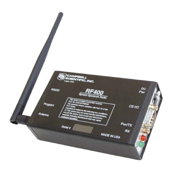
RF400 Series Spread Spectrum Data Radio/Modems FIGURE 1. RF400 The RF400 has a 9-pin serial CS I/O port and a 9-pin serial DCE RS-232 port. The CS I/O port allows the RF400 to connect to a datalogger. The RS-232 port allows direct PC connection for Setup Menu access and to create a direct connect RF400 “base station”... -
Page 11: Quick Start
RF400 Series Spread Spectrum Data Radio/Modems Quiescent Current in Standby Modes* Avg. Quiescent Advanced Setup Standard Current (mA) Standby Mode Setup RF400/ RF410 RF415 24.0 33.0 0 (no duty cycling) 0.64 0.84 0.40 0.50 * Not receiving a signal nor transmitting PHYSICAL •... - Page 12 RF400 Series Spread Spectrum Data Radio/Modems For this system you will need the following hardware or the equivalent: Two RF400s Two RF400 antennas AC adapter (Item # 15966 or part of kit #14220) Serial cable (6 ft.) for PC COM port to RF400 RS-232 port (Item # 10873 or part of Item # 14220) SC12 cable (included with RF400) Datalogger (CR10X, CR510, or CR23X)
- Page 13 RF400 Series Spread Spectrum Data Radio/Modems AC Adapter TECHNOLOGIES INC. HICKSVILLE, NEW YORK CLASS 2 TRANSFORMER MODEL NO: AP2105W INPUT: 120VAC 60Hz 20W OUTPUT: 12VDC 1.0A LISTED 2H56 E144634 MADE IN CHINA RS-232 Logan, Utah RF400 RS232 Spread Spectrum Radio CS I/O This device contains transmitter module: FCC ID: OUR-9XTREAM The enclosed device complies with Part 15 of the FCC Rules.
- Page 14 Current dataloggers and wiring panels (not mentioned in Table 1) provide 12 V on pin 8. For older products not listed, check for 12 V between CS I/O connector pin 8 and pin 2 (GND) or contact Campbell Scientific. Use default settings of RF400.
-
Page 15: System Components
RF400 Series Spread Spectrum Data Radio/Modems Auto Sense The RF400 has a default feature called “Auto Sense” that automatically configures certain RF400 settings. When you connect an RF400 to a datalogger (CS I/O port to CS I/O port) the RF400 detects the presence of the datalogger and makes its CS I/O port the active port. -
Page 16: Setup Menu
RF400 Series Spread Spectrum Data Radio/Modems Green LED activity indicates that there is an RF signal being received whose hopping sequence corresponds to the configured hopping sequence of the RF400. This does not necessarily mean that the network/radio address of the received packet corresponds with that of the RF400 (where a neighboring network exists it is a good idea to choose a unique hopping sequence). -
Page 17: Networking
RF400 Series Spread Spectrum Data Radio/Modems The Standard Setup standby modes automatically configure: • Time of Inactivity to Sleep • Time of Inactivity to Long Header • Long Header Time The default mode is the Standard Setup menu selection “2” for “< 4 mA and ½ sec Cycle.”... -
Page 18: Error Handling And Retries
RF400 Series Spread Spectrum Data Radio/Modems 4.1.3.2 ATDT Command Mode This mode is not required for basic point-to-point communication. For point-to-multipoint operation the RF400 can temporarily be put into AT Command Mode by sending a string of three ASCII characters. The default sequence to enter AT Command mode is: No characters sent for one second (before command character) “+++”characters sent (default command mode entry character) - Page 19 RF400 Series Spread Spectrum Data Radio/Modems Retries”, “Time-slots for Random Retry”, and “Bytes Transmitted before Delay” settings. STANDARD RETRY LEVELS Retry Maximum Time-Slots for Bytes Transmitted Menu Level Retries Random Retry Before Delay None 65535 1000 Medium 1000 High 1000 4.1.4.2 Number of Retries This setting specifies the maximum number of times an RF400 will re-send a packet failing to get an ACK response.
-
Page 20: Received Signal Strength
RF400 Series Spread Spectrum Data Radio/Modems For example, if you input a value of 50, then packets with hop sync info will be sent out every 5 seconds improving (shortening) the response time of a transmit/response sequence. Even though this shortens the time required to send x amount of data, the throughput is still determined by the CS I/O or RS-232 port baud rate setting. - Page 21 RF400 Series Spread Spectrum Data Radio/Modems (CSI Item # 14291) with tinned leads to connect to power at the datalogger 12 V output terminals and barrel connector to plug into the RF400’s “DC Pwr” jack. If 120 VAC is available at the site, the 120 VAC adapter alone (CSI Item # 15966) is an option.
-
Page 22: Serial Cables
RF400 Series Spread Spectrum Data Radio/Modems CSI AC adapter Item # 15966 voltage regulation (typical) while plugged into an AC outlet delivering 120.0 VAC: TABLE 3. 15966’s Voltage Regulation Current Drain Resistive Load AC Adapter Output (mA) (Ohms) (Volts) 0 (no load) ∞... -
Page 23: Antennas For The Rf400 Series
RF400 Series Spread Spectrum Data Radio/Modems A remote RF400 can be connected to a CR23X’s or CR5000’s RS-232 port with a null modem DB9M/DB9M cable (CSI Item # 14392). See Appendix F for details on power supply. 4.4 Antennas for the RF400 Series Several antennas are offered to satisfy the needs for various base station and remote station requirements. - Page 24 RF400 Series Spread Spectrum Data Radio/Modems WISP24015PTNF, boom length 17 inches, diameter 3 inches, W/ END MOUNT to fit 1 to 2 in. O.D. mast (requires either (1) COAX RPSMA-L for short runs or (2) COAX NTN-L with Antenna Surge Protector Kit) COAX RPSMA-L LMR 195 ANTENNA CABLE, REVERSE POLARITY SMA TO TYPE N MALE...
- Page 25 RF400 Series Spread Spectrum Data Radio/Modems ITEM # 14204 900 MHZ OMNI ½ WAVE WHIP 0 dBd ITEM # 14201 900 MHZ YAGI 9 dBd w/MOUNTS ITEM #14205 900 MHz YAGI 6 dBd w/MOUNTS ITEM # 14221 900 MHZ OMNI COLLINEAR 3 dBd w/MOUNTS...
- Page 26 RF400 Series Spread Spectrum Data Radio/Modems ITEM #15970 900 MHZ Indoor OMNI 1 dBd Window/Wall Mounted ITEM #16005 2.4 GHz OMNI HALF WAVE WHIP 0 dBd ITEM #16755 2.4 GHz ENCLOSED YAGI, 13 dBd w/MOUNTS FIGURE 4. Some FCC Approved Antennas...
-
Page 27: Antenna Cables And Surge Protection
RF400 Series Spread Spectrum Data Radio/Modems FIGURE 5. Example COAX RPSMA-L Cable for Yagi or Omni Colinear FIGURE 6. Antenna Surge Protector 4.5 Antenna Cables and Surge Protection 4.5.1 Antenna Cables The 14201, 14203, 14205, 14221, and 16755 antennas require an antenna cable;... -
Page 28: Antenna Surge Protector Kit
RF400 Series Spread Spectrum Data Radio/Modems • When use of COAX RPSMA would result in too much signal loss (see page H-3) • When the RF400 series radio will be used in an environment susceptible to lightning or electro-static buildup 4.5.3 Antenna Surge Protector Kit The Surge Protector Kit for the RF400 series radios includes the following: •... -
Page 29: Software Setup
RF400 Series Spread Spectrum Data Radio/Modems 5. Software Setup 5.1 Point-to-point Set-up parameters are configured the same for the two RF400s. The RF400 defaults to radio address “0” (zero) which works for many applications. See Section 4.2 for power supply options. 5.2 Point-to-multipoint The radio addresses for a base RF400 and its remotes are typically configured to be different from one another. - Page 30 RF400 Series Spread Spectrum Data Radio/Modems Main Menu SW Version 6.425 (for example) (1) Standard Setup (2) Advanced Setup (3) Restore Defaults (4) Show All Current and Default Settings (5) Save All Parameters and Exit Setup (9) Exit Setup without Saving Parameters Enter Choice: Press “1”...
-
Page 31: Remote Station Setup
RF400 Series Spread Spectrum Data Radio/Modems Select a Radio Address (0 – 1023). The radio addresses must be the same in point-to-point communications (for point-to-multipoint communications you could set the base RF400 to 0 and the remotes to 1, 2, 3, etc.). It is a good idea to label each RF400 indicating the configured network address, radio address, hopping sequence, etc. - Page 32 RF400 Series Spread Spectrum Data Radio/Modems Point-to-multipoint Complete steps 1 to 4 above making the remote stations’ Network Addresses and Hopping Sequences the same as the base station’s. While in Standard Setup verify that the active interface is “Auto Sense” and give each remote RF400 a unique Radio Address. You should label each RF400 (with masking tape) indicating the configured network address, radio address, hopping sequence, etc.
-
Page 33: Loggernet Configuration
RF400 Series Spread Spectrum Data Radio/Modems power and intermittent repeater sites may not be a problem. Test such a site with a representative setup before committing to it (see Troubleshooting Section 6). Keep in mind that commercial sites tend to evolve. Such a site may work now but could change in the future with the addition of new equipment. -
Page 34: Pc208W Configuration
RF400 Series Spread Spectrum Data Radio/Modems 3 dBd Omni Collinear 9 dBd Yagi 6 dBd Yagi 0 dBd Half-wave CS I/O CS I/O CS I/O RF400 RF400 RS-232 RF400 RF400 DATALOGGER DATALOGGER DATALOGGER CS I/O CS I/O CS I/O AC Adapter FIGURE 8. - Page 35 RF400 Series Spread Spectrum Data Radio/Modems (4) Datalogger Station Settings (a) Example “Dialed Using Generic Dial String”: D1000 T"+++" R"OK"9200 T"ATDT3001^m"R"OK"1200 T"ATCN^m"R"OK"1200 (i) D1000 creates a 1 second delay (ii) T sends quoted string w/o waiting for a character echo (iii) +++ is string sent to put RF400 in AT Command mode (use other character if phone modems in path) (iv) R”OK”9200 waits up to 9.2 sec for RF400 “OK”...
-
Page 36: Troubleshooting
RF400 Series Spread Spectrum Data Radio/Modems 6. Troubleshooting If you can’t connect, check out these possible causes: Datalogger or Wiring Panel lacks 12 V power on pin 8 of CS I/O port The RF400 should go through its initialization with red and green LEDs lighting (see Section 4.1.1) when serial cable is connected if 12 V is present on CS I/O connector (see Quick Start Table 1). - Page 37 RF400 Series Spread Spectrum Data Radio/Modems RF400 receiver “de-sensing” from nearby transmitter This problem can be observed from LED behavior when operating a hand- held radio near an RF400 that is receiving collected data from a remote station. If you key a hand-held 150 MHz or 450 MHz transmitter, even though its frequency of operation is far removed from the 900 MHz band, its close proximity to the base RF400 can overwhelm (de-sense) the RF400 receiver resulting in failed packets and LoggerNet/PC208W...
- Page 38 RF400 Series Spread Spectrum Data Radio/Modems 10. PC208W.dnd file corrupted The remote possibility exists that this file has become corrupted in your PC. After you create the Network Map in PC208W, you can back up PC208W.dnd in case this should happen. If this appears likely, exit PC208W and copy and paste your backup file over the suspect .dnd file to restore proper operation.
-
Page 39: Part 15 Fcc Compliance Warning
Warning Changes or modifications to the RF400 series radio systems not expressly approved by Campbell Scientific, Inc. could void the user’s authority to operate this product. Note: This equipment has been tested and found to comply with the limits for a Class B digital device, pursuant to part 15 of the FCC Rules. - Page 40 This is a blank page.
-
Page 41: Setup Menu
Appendix B. Setup Menu Here is the structure of the RF400 series’ built-in Setup Menu system which can be accessed by configuring a terminal emulator program such as Procomm HyperTerminal to 9600 baud (8-N-1) and pressing the “Program” button on the RF400 with RF400’s RS-232 port cabled to appropriate COM port of PC. - Page 42 Appendix B. Setup Menu ii) Radio Standby Modes (1) Standby Mode (0 => 24 mA Always ON 3 => 4 mA 1/2 sec Cycle) (4 => 2 mA 1 sec Cycle 5 => 1 mA 2 sec Cycle) (6 => .6 mA 4 sec Cycle 7 =>.4 mA 8 sec Cycle) (2) Time of Inactivity to Sleep (units of 100 msec;...
- Page 43 Appendix B. Setup Menu 4 => 38.3k (2) RS-232 Parity: 0 => None 1 => Odd 2 => Even (3) RS-232 Character Length: 0 => 8 bits 1 => 7 bits (4) RS-232 Stop Bits: 0 => 1 1 => 2 Restore Defaults Show All Current and Default Settings Save All Parameters and Exit Setup...
- Page 44 Appendix B. Setup Menu This is a blank page.
- Page 45 Appendix C. RF400 Series Address and Address Mask Address An RF400’s address is 16 bits: (0 - 1111,1111,1111,1111) binary (0 - ffffh) hexadecimal 0 – 65535) decimal The two parts of the address are the “Network Address” and the “Radio Address.”...
- Page 46 Appendix C. RF400 Series Address and Address Mask four bits are not compared, any remote RF400 with Radio Address of 0 to 1111 (decimal 0 to 15) will be received by the base station. This allows multiple remotes in a network to be received by the base without changing the base Radio Address (the remotes cannot receive the base, however).
- Page 47 Appendix C. RF400 Series Address and Address Mask NET ADDRESS RADIO ADDRESS COMBINED 16-BIT ADDRESS (decimal) (decimal) (hexadecimal) 001D 001E 001F 0020 1022 03FE 1023 03FF 0400 0401 0800 0801 0C00 0C01 1000 1001 1400 1401 1800 1801 1C00 1C01 2000 2001 2400...
- Page 48 Appendix C. RF400 Series Address and Address Mask NET ADDRESS RADIO ADDRESS COMBINED 16-BIT ADDRESS (decimal) (decimal) (hexadecimal) 3C00 3C01 4000 4001...
- Page 49 Appendix D. Advanced Setup Standby Modes The Standard Setup menu selections should fill the majority of user needs. The following information is given in case you need to program a non-standard standby mode. The Standard Setup menu selections do not correspond with Advanced Setup menu entries.
- Page 50 Appendix D. Advanced Setup Standby Modes In general, these inactivity timers should be set so that the RF400 stays on (receiving or transmitting, not in standby mode) longer than the quiet times during communication. You can experiment with this to see how it works. TIME OF INACTIVITY TO SLEEP The amount of receiver inactivity time desired before entering Standby Mode.
- Page 51 CS I/O Port The CS I/O port is Campbell Scientific's input/output port. It is not a standard RS-232 pin-out. The following table provides pin-out information on the port when connected to a datalogger.
- Page 52 Appendix E. RF400 Series Port Pin Descriptions CS I/O CONNECTOR, 9-PIN D-SUB MALE FUNCTION DESCRIPTION Sources 5 VDC to power peripherals GND for pin 1 and signals Ring Raised by modem to put datalogger into telecommunications mode Serial data receive line Modem Enable Raised when datalogger determines that associated modem raised the...
- Page 53 Appendix F. Datalogger RS-232 Port to RF400 Series Radio A connection from RF400 RS-232 port to CR23X or CR5000 RS-232 port requires a 9-pin male to 9-pin male null-modem cable. This cable is available as CSI Item # 14392. A 12-Volt Field Power Cable (Item # 14291) or AC adapter (Item # 15966) must be installed to furnish 12 V to the “DC Pwr”...
- Page 54 This is a blank page.
- Page 55 Appendix G. Short-Haul Modems Set SRM-5A at PC end to “DCE” mode. Set SRM-5A at RF400 end to “DTE” mode. The PC to SRM-5A cable is typically a 9-pin female to 25-pin male (CSI Item # 7026). The SRM-5A to RF400 cable is 25-pin male to 9-pin male available as CSI Item # 14413.
- Page 56 Appendix G. Short-Haul Modems With short-haul modems it is necessary to configure the base NOTE station RF400’s “RS-232 Auto Power Down Enable” (in the Advanced Setup \ Interface Parameters menu) to mode "0" which will maintain the radio's RS-232 port always active. This results in an additional constant 2 mA current drain by the RF400.
- Page 57 Appendix H. Distance vs. Antenna Gain, Terrain, and Other Factors RF Path Examples Distance Achieved Antennas Path Between Radios (miles) 14204 OMNI ½ Wave 0 dBd* Whip Virtual line-of-sight on valley floor with wetland foliage. 14204 OMNI ½ Wave 0 dBd Whip 14204 OMNI ½...
- Page 58 Appendix H. Distance vs. Antenna Gain, Terrain, and Other Factors How Far Can You Go? Distance Estimates for Spread Spectrum Radios Overview There is a great deal of interest in estimating the distance you can expect to achieve with the RF400 radios. Also of interest are the effects of cable length, antenna gain, and terrain.
- Page 59 Appendix H. Distance vs. Antenna Gain, Terrain, and Other Factors Pr => signal power at the radio receiver in dBm The signal power at the receiver (Pr) must exceed the receiver sensitivity (−110 or –104 dBm) by a minimum of 6 dB for an effective link. The amount that Pr exceeds –110 dBm or –104 dBm (2.4 GHz) is the link margin.
-
Page 60: Antenna Gain
Appendix H. Distance vs. Antenna Gain, Terrain, and Other Factors Antenna Gain Antenna gain is specified either in dBi (decibels of gain relative to an isotropic radiator) or in dBd (decibels of gain relative to a dipole). The relationship is: dBi = dBd + 2.15 Some antennas that are FCC approved for use with the RF400 series are: Mfg. - Page 61 Appendix H. Distance vs. Antenna Gain, Terrain, and Other Factors As mentioned before, free space conditions are the ideal, but seldom actually seen. The higher the antenna height relative to the terrain in the line of sight path, the closer to free space conditions. Antenna height is everything! Here are some additional propagation effects that increase the path losses: Diffraction This is caused by objects close to the line of sight path.
- Page 62 Appendix H. Distance vs. Antenna Gain, Terrain, and Other Factors Here is a table which gives calculated path loss (Lp) values at 900 MHz for the , and 4 powers of distance; the equations (for 915 MHz) are: power) = 95.8 + 20 × log ( d ) dB Lp (2 (d in miles) power) = 95.8 + 30 ×...
- Page 63 Appendix H. Distance vs. Antenna Gain, Terrain, and Other Factors Use –107 dBm for Pr, solve for Lp: Lp = 135 dB Use the 3 to 4 power tables: Range from ~9 (4 power) to ~22 (3 power) miles Example #2 Base has MaxRad BMOY8905 Yagi, with 50’...
- Page 64 Appendix H. Distance vs. Antenna Gain, Terrain, and Other Factors This is a blank page.
- Page 65 Appendix I. Phone to RF400 Series Where a phone to RF400 Base is desired, the following configurations will provide Point-to-Point or Point-to-Multipoint communications. To have a base datalogger in this configuration requires that another RF400 be added at the base. HARDWARE REQUIREMENTS RF400s COM210...
- Page 66 Appendix I. Phone to RF400 Series Phone Modem 1) Baud Rate – 9600 2) Modem Pick List – per PC’s phone modem 3) Extra Response Time – 2000 ms Datalogger – Dialed Using Phone # at Base site RF400 CONFIGURATION Base RF400 1) Active Interface: “COM2xx to RF400”...
- Page 67 Appendix I. Phone to RF400 Series PC208W SETUP Network Map COM1 Modem1 Generic1 CR10X_1 CR10X_2 COM port - default settings Phone Modem 1) Baud Rate – 9600 2) Modem Pick List – per PC’s phone modem 3) Extra Response Time – 2000 ms Generic Modem 1) Dialed Using phone # at base site 2) √...
- Page 68 Appendix I. Phone to RF400 Series FIGURE I-1. LoggerNet Point-to-Multipoint Setup HARDWARE After configuring LoggerNet or PC208W and the RF400s you are ready to set up hardware. The PS512M null-modem connectors (it’s not important which connector goes to which unit) connect via SC12 cables to the COM210 and the base RF400 CS I/O port.
- Page 69 Appendix J. Monitor CSAT3 via RF400 Series Procedure for installing a pair of RF400 series spread spectrum radios for monitoring a CSAT3 system at a distance. This function has traditionally been implemented by running a short haul modem cable between CSAT3 and PC. HARDWARE REQUIREMENTS •...
- Page 70 Appendix J. Monitor CSAT3 via RF400 Series (5) Select “1” for “Standard Setup” and configure the following (a) Active Interface – leave at default “Auto Sense” (b) Network Address – can be default “0” if no neighboring RF400 networks are operating; otherwise choose a different network address (see RX LED Test below).
- Page 71 Appendix J. Monitor CSAT3 via RF400 Series (2) Remote station (a) Connect 12 V power supply to RF400 (can be either 120V AC adapter or 12V Field Power Cable) (b) Connect 9 pin male to 9 pin male null-modem cable from CSAT3 RS-232 connector to RF400’s RS-232 connector.
- Page 72 Appendix J. Monitor CSAT3 via RF400 Series This is a blank page.
- Page 73 Appendix K. RF400/RF410 Pass/Fail Tests This appendix describes a method to functionally test RF400/RF410 system components including: • PC COM port • SC12 serial cable • RF400/RF410 • RF400/RF410 Antenna Hardware/Software Required PC with one available COM port Terminal Program (HyperTerminal or Procomm Two RF400/RF410s Two SC12 serial cables...
- Page 74 Appendix K. RF400/RF410 Pass/Fail Tests (d) Emulation: TTY (e) ASCII (f) COM1 (or any available COM port) NOTE With some versions of HyperTerminal after changing a setting it is necessary to do a “Call Disconnect” (or “Disconnect”) followed by a “Call Connect” (or “Call”) for the new setting to register.
- Page 75 Appendix K. RF400/RF410 Pass/Fail Tests TESTING RF400/RF410s After verifying the functionality of the terminal program and the integrity of the serial cable and COM port, proceed as follows: (1) Connect 12V power to an RF400/RF410. This can be from an AC adapter (Item # 14220 or Field Power Cable (Item # 14291) with 12V battery pack attached (see step 12 below).
- Page 76 Appendix K. RF400/RF410 Pass/Fail Tests (9) Make sure that no antennas are attached to the RF400/RF410s (10) Label the other RF400/RF410, “Remote” (11) Insert jumper into the Remote RF400/RF410’s RS-232 connector pins 2 and 3 (using a U-shaped portion of a paper clip) allowing data received from base RF400/RF410 to be transmitted back to terminal screen by remote RF400/RF410.
- Page 77 Appendix K. RF400/RF410 Pass/Fail Tests (b) Choose an open area free of large metal objects within 10 feet of the RF400/RF410s (can be indoors or outdoors). (c) Attach a 1/4 wave omni antenna (Item # 14310) to base RF400/RF410 (d) Set up remote RF400/RF410 with NO antenna (e) Separate RF400/RF410s by 5 feet (f) Type 8 groups of 5 characters on the terminal (aaaaabbbbbccccc etc.) (g) You should receive 100% of the characters...
- Page 78 Appendix K. RF400/RF410 Pass/Fail Tests FIGURE K-3. 3 dBd 900 MHz Collinear Omni Antenna (d) Set up remote RF400/RF410 with NO antenna and with antenna connector 20 inches above floor. (e) Arrange antenna distance apart according to following table. TABLE K-1. 900 MHz Gain Antenna Test Distances Antenna Gain Power Ratio...
- Page 79 Appendix L. RF400/RF410 Average Current Drain Calculations For remote sites with tight power budgets due to solar or battery power supplies, the following will help determine average current consumption. The RF400/RF410’s average current drain is based on: • Standby mode of RF400/RF410 •...
- Page 80 Appendix L. RF400/RF410 Average Current Drain Calculations The base RF400/RF410’s total average current (It) can be calculated over an interval (T) as follows: It = Is + Ih + Iq + Ir + Ii Is = {table value} (ms) × where "...
- Page 81 Appendix L. RF400/RF410 Average Current Drain Calculations EXAMPLE #1 (Remote RF400/RF410 in default standby mode) There is a Point-to-Point system with base RF400/RF410 and remote RF400/RF410. The remote station senses weather conditions and sends low- resolution data to final storage. The base station collects 10 data points from the remote station once per minute.
- Page 82 Appendix L. RF400/RF410 Average Current Drain Calculations EXAMPLE #2 (Base RF400/RF410 in default standby mode) The base RF400/RF410 in the above example does more receiving and less transmitting than the remote RF400/RF410 so you might expect less average current drain, however, the amount of data being transmitted per minute is small, and the long header required is significant.
- Page 83 Appendix L. RF400/RF410 Average Current Drain Calculations EXAMPLE #3 (Base RF400/RF410 in “<0.4 mA, 8 sec Delay” standby mode) The RF400/RF410s in this example are configured for the lowest possible average standby mode current (Advanced Setup Menu selection 7). The same amount and frequency of data are collected as in Example 1.
- Page 84 Appendix L. RF400/RF410 Average Current Drain Calculations EXAMPLE #4 (Remote RF400/RF410 in “<0.4 mA, 8 sec Delay” standby mode) The RF400/RF410s in this example are configured for the lowest possible average standby mode current (Advanced Setup Menu selection 7). The same amount and frequency of data are collected as in Example 1.
- Page 85 Appendix L. RF400/RF410 Average Current Drain Calculations EXAMPLE #5 (Base RF400/RF410 in default “<4 mA, 1 sec Delay” standby mode) The RF400/RF410s in this example are configured for the default average standby mode current. The same amount of data (10 data points) are collected as in Example 1, however the frequency of collection is changed from once a minute to once an hour.
- Page 86 Appendix L. RF400/RF410 Average Current Drain Calculations EXAMPLE #6 (Base RF400/RF410 in “<0.4 mA, 8 sec Delay” standby mode) The RF400/RF410s in this example are configured for the lowest possible average standby mode current (Advanced Setup Menu selection 7). The same amount of data are collected as in Example 1, however the frequency of collection is changed from once a minute to once an hour.
- Page 87 Appendix L. RF400/RF410 Average Current Drain Calculations EXAMPLE #7 (Remote RF400/RF410 in “<0.4 mA, 4 sec Cycle” standby mode ) The RF400/RF410s in this example are configured for the lowest possible average standby mode current (Advanced Setup Menu selection 7). The same amount of data are collected as in Example 1, however the frequency of collection is extended to once an hour.
- Page 88 Appendix L. RF400/RF410 Average Current Drain Calculations This is a blank page. L-10...
- Page 89 This is a blank page.
- Page 90 Campbell Scientific Companies Campbell Scientific, Inc. (CSI) 815 West 1800 North Logan, Utah 84321 UNITED STATES www.campbellsci.com info@campbellsci.com Campbell Scientific Africa Pty. Ltd. (CSAf) PO Box 2450 Somerset West 7129 SOUTH AFRICA www.csafrica.co.za sales@csafrica.co.za Campbell Scientific Australia Pty. Ltd. (CSA)
Need help?
Do you have a question about the R410 and is the answer not in the manual?
Questions and answers