
Related Manuals for Campbell RF401


Summary of Contents for Campbell RF401
- Page 1 RF401/RF411/RF416 Spread Spectrum Data Radio/Modem 5/05 C o p y r i g h t ( c ) 2 0 0 1 - 2 0 0 5 C a m p b e l l S c i e n t i f i c ,...
- Page 2 Warranty and Assistance The RF401 SERIES SPREAD SPECTRUM DATA RADIO/MODEMS are warranted by CAMPBELL SCIENTIFIC, INC. to be free from defects in materials and workmanship under normal use and service for twelve (12) months from date of shipment unless specified otherwise. Batteries have no warranty.
- Page 3 Where an AC adapter is used, CSI recommends Item # 15966. This AC adapter is included as part of Item # 14220 RF401 Series Base Station Cable/Power Kit. Any other AC adapter used must have a DC output not exceeding 16.5 Volts measured without a load to avoid...
- Page 4 This is a blank page.
-
Page 5: Table Of Contents
4.5.3 Antenna Surge Protector Kit............24 5. Software Setup............25 5.1 Point-to-Point..................25 5.2 Point-to-Multipoint .................25 5.3 PakBus Configuration................25 5.4 Example Setups ..................25 5.4.1 Direct PC to RF401 Series Base Station Setup......25 5.4.2 Remote Station Setup..............28 5.4.3 LoggerNet Configuration..............29 5.4.4 PC208W Configuration ..............30 6. Troubleshooting ............32... - Page 6 C. RF401 Series Address and Address Mask....C-1 D. Advanced Setup Standby Modes ......D-1 E. RF401 Series Port Pin Descriptions ...... E-1 F. Datalogger RS-232 Port to RF401 Series Radio..F-1 G. Short-Haul Modems ..........G-1 H. Distance vs. Antenna Gain, Terrain, and Other Factors ............H-1...
- Page 7 6. Some FCC Approved Antennas............20-22 7. Example COAX RPSMA-L Cable for Yagi or Omni Colinear....23 8. Antenna Surge Protector................23 9. Enclosure with Antenna Surge Protector for RF401 ........24 10. Point-to-Multipoint System ..............30 11. PC208W Datalogger Generic Dial String..........32 G-1. Short-Haul Modem to RF401 Setup..........G-1 I-1.
- Page 8 RF401 Table of Contents This is a blank page.
-
Page 9: Introduction
(see Appendix H for a discussion of antenna gain and other factors affecting distance). The RF411 differs from the RF401 in that it operates at 922 MHz for regions such as Australia, New Zealand, and Israel. The RF411’s communication range is the same as that of the RF401. -
Page 10: Rf400 And Rf401 Differences
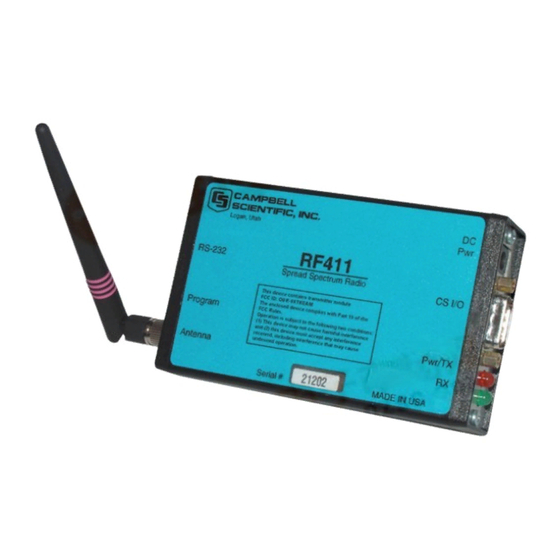
RF401 Series Spread Spectrum Data Radio/Modems FIGURE 1. RF411 The RF401 has a 9-pin serial CS I/O port and a 9-pin serial DCE RS-232 port. The CS I/O port allows the RF401 to connect to a datalogger. The RS-232 port allows direct PC connection for Setup Menu access and to create a direct connect RF401 “base station”... -
Page 11: Cr206, Cr211, Cr216
Rf_Protocol in the dataloggers. When the Rf_Protocol setting is 1, the CR206 will operate just like the CR205; when the setting is 2, the CR206 will use the same RF PakBus protocol as the RF401. 2. RF401 Series Specifications POWER •... -
Page 12: Quick Start
Two RF401s Two RF401 antennas AC adapter (Item # 15966 or part of kit #14220) Serial cable (6 ft.) for PC COM port to RF401 RS-232 port (Item # 10873 or part of Item # 14220) SC12 cable (included with RF401) Datalogger (CR10X, CR510, or CR23X) Field Power Cable (Item # 14291) if datalogger or wiring panel doesn’t... - Page 13 The red LED then begins to flash on and off. The red LED flashes once every half second in the default “< 4 mA, ½ sec Cycle” standby mode as the RF401 wakes up briefly and listens for RF transmissions with an average current consumption less than 4 mA.
- Page 14 PS512M Power Supply < 1712 When you connect power to the RF401 (through the SC12 cable or the optional Field Power Cable) you should see the power-up sequence of red and green LEDs described in Step 1 (assuming datalogger is powered).
- Page 15 RF401 settings. When you connect an RF401 to a datalogger (CS I/O port to CS I/O port) the RF401 detects the presence of the datalogger and makes its CS I/O port the active port. When the protocol is set to Transparent (RF400 compatible), the CS I/O port mode used for Auto Sense is Modem Enabled (ME).
-
Page 16: System Components
4.1 RF401 Series Data Radios 4.1.1 Indicator LEDs The RF401 has a red LED labeled “Pwr/TX” and a green LED labeled “RX.” When 12V power is applied the red LED lights for ten seconds. About 3 seconds after power-up the green LED lights for a second. Ten seconds after power-up the selected standby mode begins to control the red LED. - Page 17 RF401 Series Spread Spectrum Data Radio/Modems FIGURE 4. Device Configuration screen for setting up the RF401, RF411, RF416 radios. The circled parameter shows where you choose the protocol setting.
- Page 18 4.1.2.2 Protocol The RF401 Protocol choices are “Transparent”, “PB Aware”, and “PB Node”. The factory default setting for Protocol is “Transparent.” RF401 radios set to the Transparent protocol provide the same functionality as the RF400 radios, and therefore can coexist in the same network. The “PB Aware” and “PB...
-
Page 19: Networking-Transparent Mode
1100 ms < .4 mA 8 sec 8100 ms *Maximum time it takes to get an RF Packet sent and for the other RF401 to respond. The Standard Setup standby modes automatically configure: • Time of Inactivity to Sleep •... - Page 20 RF401 Series Spread Spectrum Data Radio/Modems to this is that an RF401 base station can receive packets from multiple remote stations if the base station’s Radio Address Mask is other than the maximum allowed number of 3ffh (hexadecimal). For example, if the base station’s radio address mask is set to 0, it will receive packets from any radio that has a matching radio network address (regardless of its radio address).
-
Page 21: Error Handling And Retries
CRC. The RF401 rejects a received packet (doesn’t send it out a port) if the packet’s header address fails to match the RF401 address, if an RF module receive error is detected, or if the RF packet’s CRC test fails. - Page 22 4.1.4.4 Number of Bytes Transmitted before Delay This feature prevents an RF401 Series radio which has lots of data to transfer from tying up a network until it is finished. The range of settings is 1 to 65535.
-
Page 23: Received Signal Strength
CRC. If 0 retries are configured, the receiving RF401 will simply throw away any packet that fails the CRC. This reading is cleared upon exiting Setup Menu or cycling RF401 12 V power. -
Page 24: Power Supplies
If 120 VAC is available at the site, the 120 VAC adapter alone (CSI Item # 15966) is an option. A 12 V supply may connect to either the RF401’s “DC Pwr” jack or CS I/O pin 8 (or both, since there is diode isolation between supply inputs). The 12 V supply inputs are diode protected against the application of reverse polarity power. - Page 25 (including the CSI AC adapter Item # 272) will cause immediate damage if plugged into the RF401 even briefly. It is also possible to damage the RF401 with an AC adapter labeled as low as “12 VDC” because it may output an open-circuit (no current drain) voltage exceeding the maximum.
-
Page 26: Serial Cables
4.3 Serial Cables In an RF401 base station, a straight-through DB9M/DB9F RS-232 cable will connect from the RF401’s RS-232 port to the PC COM port. This cable is part of the optional Base Cable/Power Kit (CSI Item # 14220). A remote RF401 normally uses the included SC12 cable to connect the... -
Page 27: Antennas For The Rf401 Series
RF401 Series Spread Spectrum Data Radio/Modems A remote RF401 can be connected to a CR23X’s or CR5000’s RS-232 port with a null modem DB9M/DB9M cable (CSI Item # 14392). See Appendix F for details on power supply. 4.4 Antennas for the RF401 Series Several antennas are offered to satisfy the needs for various base station and remote station requirements. - Page 28 In order to comply with the FCC RF exposure CAUTION requirements, the RF401 series may be used only with approved antennas that have been tested with this radio and a minimum separation distance of 20 cm must be maintained from the antenna to any nearby persons.
- Page 29 RF401 Series Spread Spectrum Data Radio/Modems ITEM # 14204 900 MHZ OMNI ½ WAVE WHIP 0 dBd ITEM # 14201 900 MHZ YAGI 9 dBd w/MOUNTS ITEM #14205 900 MHz YAGI 6 dBd w/MOUNTS ITEM # 14221 900 MHZ OMNI COLLINEAR 3 dBd w/MOUNTS...
- Page 30 RF401 Series Spread Spectrum Data Radio/Modems ITEM #15970 900 MHZ Indoor OMNI 1 dBd Window/Wall Mounted ITEM #16005 2.4 GHz OMNI HALF WAVE WHIP 0 dBd ITEM #16755 2.4 GHz ENCLOSED YAGI, 13 dBd w/MOUNTS FIGURE 6. Some FCC Approved Antennas...
-
Page 31: Antenna Cables And Surge Protection
Protection Kit. The COAX NTN-L cable is a low-loss RG8 coaxial cable that requires the 14462 surge protector in order to connect to an RF401 series radio. The RG8 / Antenna Surge Protector are recommended in preference to the COAX RPSMA in the following applications: •... -
Page 32: Antenna Surge Protector Kit
When use of COAX RPSMA would result in too much signal loss (see page H-3) • When the RF401 series radio will be used in an environment susceptible to lightning or electro-static buildup 4.5.3 Antenna Surge Protector Kit The Surge Protector Kit for the RF401 series radios includes the following: •... -
Page 33: Software Setup
1, and the second remote’s radio address might be 2, etc. For the base RF401 to be able to transmit to a remote RF401, the base’s Radio Address must be temporarily changed to match that of the remote. The address... - Page 34 Baud rate: 9600, 8-N-1 Flow control: none d. Emulation: TTY ASCII (raw) COM1 (direct connect) Power up RF401 (wait two seconds) and press “Program” button for one second to see the following display. Main Menu SW Version 6.425 (for example) (1) Standard Setup...
- Page 35 RF401 Series Spread Spectrum Data Radio/Modems Leave Active Interface in “Auto Sense” (default setting) for most applications. In Auto Sense the RF401 will test for 5 V on CS I/O port (pin 1) to determine if a datalogger is present and if so select the CS I/O port.
-
Page 36: Remote Station Setup
Addresses and Hopping Sequences the same as the base station’s. b. While in Standard Setup verify that the active interface is “Auto Sense” and give each remote RF401 a unique Radio Address. You should label each RF401 (with masking tape) indicating the configured network address, radio address, hopping sequence, etc. -
Page 37: Loggernet Configuration
In the case of point-to-multipoint, the RF401s are always represented in the LoggerNet Setup map (as an RF400) so that LoggerNet can temporarily change the base RF401’s Radio Address to communicate with one out of a group of remote RF401s. -
Page 38: Pc208W Configuration
RF401 Series Spread Spectrum Data Radio/Modems (1) Point-to-multipoint (a) Setup map: ComPort_1 RF400 RF400Remote_1 CR10X_1 RF400Remote_2 CR10X_2 RF400Remote_3 CR10X_3 (2) All RF400Remotes have the same Network Address but each RF400Remote must have a unique Radio Address. (3) Extra Response Times are typically 0 s... - Page 39 (i) D1000 creates a 1 second delay (ii) T sends quoted string w/o waiting for a character echo (iii) +++ is string sent to put RF401 in AT Command mode (use other character if phone modems in path) (iv) R”OK”9200 waits up to 9.2 sec for RF401 “OK” response (v) ATDT3001 changes radio address to talk to remote RF401 with network address of 12 and radio address of 1.
-
Page 40: Troubleshooting
Datalogger or Wiring Panel lacks 12 V power on pin 8 of CS I/O port The RF401 should go through its initialization with red and green LEDs lighting (see Section 4.1.1) when serial cable is connected if 12 V is present on CS I/O connector (see Quick Start Table 1). - Page 41 75 mA transmitter bursts lasting only a few milliseconds. Lightning damage to RF401 Swap in a known good RF401 with the same settings and see if this cures the problem. Lightning damage can occur leaving no visible indications.
- Page 42 11. RF401 has wrong Network Address, Radio Address, Hopping Sequence, or Standby Mode It is improbable that an RF401 that has been working would ever change address, hopping sequence or other settings. However, check the settings for the unlikely event this may have happened. Try “Restore Defaults”...
- Page 43 Appendix A. Part 15 FCC Compliance Warning Changes or modifications to the RF401 series radio systems not expressly approved by Campbell Scientific, Inc. could void the user’s authority to operate this product. Note: This equipment has been tested and found to comply with the limits for a Class B digital device, pursuant to part 15 of the FCC Rules.
- Page 44 This is a blank page.
- Page 45 Appendix B. Setup Menu Here is the structure of the RF401 series’ built-in Setup Menu system which can be accessed by configuring a terminal emulator program such as Procomm HyperTerminal to 9600 baud (8-N-1) and pressing the “Program” button on the RF401 with RF401’s RS-232 port cabled to appropriate COM port of PC.
- Page 46 Appendix B. Setup Menu g) RF Protocol Transparent ii) PakBus Aware iii) PakBus Node Advanced Setup a) Radio Parameters Radio Address Parameters (1) Net Address (0 – 63) (2) Radio Address (0 – 1023) (3) Net Address Mask (0 – 3fh) (4) Radio Address Mask (0 –...
- Page 47 (3) Number of bytes transmitted before delay (1 – 65535) (4) Sync Timer Setting; (units of 100 msec; 0 – 255) vi) Configure RF401 for Firmware Download b) Interface Parameters CSDC Address (Not Active): (7 or 8) ii) RS-232 Auto Power Down Enable 0 =>...
- Page 48 Appendix B. Setup Menu This is a blank page.
- Page 49 Address mask The RF401 has a user programmable 16-bit address mask. Like the address, the address mask is divided into two parts. The six most significant bits are the Network Address Mask and the remaining ten bits are the Radio Address Mask.
- Page 50 Appendix C. RF401 Series Address and Address Mask four bits are not compared, any remote RF401 with Radio Address of 0 to 1111 (decimal 0 to 15) will be received by the base station. This allows multiple remotes in a network to be received by the base without changing the base Radio Address (the remotes cannot receive the base, however).
- Page 51 Appendix C. RF401 Series Address and Address Mask NET ADDRESS RADIO ADDRESS COMBINED 16-BIT ADDRESS (decimal) (decimal) (hexadecimal) 001D 001E 001F 0020 1022 03FE 1023 03FF 0400 0401 0800 0801 0C00 0C01 1000 1001 1400 1401 1800 1801 1C00 1C01...
- Page 52 Appendix C. RF401 Series Address and Address Mask NET ADDRESS RADIO ADDRESS COMBINED 16-BIT ADDRESS (decimal) (decimal) (hexadecimal) 3C00 3C01 4000 4001...
-
Page 53: Advanced Setup Standby Modes
Appendix D. Advanced Setup Standby Modes The Standard Setup menu selections should fill the majority of user needs. The following information is given in case you need to program a non-standard standby mode. The Standard Setup menu selections do not correspond with Advanced Setup menu entries. - Page 54 Appendix D. Advanced Setup Standby Modes In general, these inactivity timers should be set so that the RF401 stays on (receiving or transmitting, not in standby mode) longer than the quiet times during communication. You can experiment with this to see how it works.
- Page 55 RS-232 data for up to 8 seconds while waiting for the other RF401 to wake up before transmitting it. Also, if the RF401 is doing a lot of retries, that can take extra time and require flow control to avoid buffer over-run.
- Page 56 Used by datalogger with SDE and TX lines to transfer data to synchronous devices 12V supplied by Sources 12 VDC to power datalogger peripherals Serial data transmit line I = Signal Into the RF401, 0 = Signal Out of the RF401...
- Page 57 A 12-Volt Field Power Cable (Item # 14291) or AC adapter (Item # 15966) must be installed to furnish 12 V to the “DC Pwr” connector on the RF401. The RF401 can operate with Active Interface in either the Auto Sense mode (default) or in the RS-232 mode with this configuration.
- Page 58 This is a blank page.
-
Page 59: Short-Haul Modems
(see Section 5.3.1, 4.d). 12 V power for the base RF401 can be supplied by an AC adapter as shown or a Field Power Cable (see Power Supplies in Section 4.4). Current dataloggers... - Page 60 RS-232 port always active. This results in an additional constant 2 mA current drain by the RF401. If you don’t do this, the base RF401’s RS-232 port will turn off 30 seconds after activity and the attached SRM-5A which gets its power from the port will not receive any messages from the PC.
- Page 61 ANTENNA HEIGHT In situations where the RF401 antennas are situated virtually line-of-sight, the elevation of antennas (by choice of site or by installing a tower or mast) can substantially increase signal strengths. The amount of increase depends on factors in the propagation path between the radios including terrain, foliage, and man-made structures.
- Page 62 There is a great deal of interest in estimating the distance you can expect to achieve with the RF401 radios. Also of interest are the effects of cable length, antenna gain, and terrain. Some of these items are easy to quantify (cable loss, for instance);...
- Page 63 1 milliWatt. The formula is: dBm = 10 log (Pt) with Pt expressed in milliWatts. Transmitter Power (Pt) (milliWatts) 50 (RF416) 100 (RF401 or RF411) 1000 5000 Cable Loss Cable loss is a function of cable type, length, and frequency and is usually specified as attenuation (dB) per 100’...
- Page 64 Antenna gain is specified either in dBi (decibels of gain relative to an isotropic radiator) or in dBd (decibels of gain relative to a dipole). The relationship is: dBi = dBd + 2.15 Some antennas that are FCC approved for use with the RF401 series are: Mfg. Antenna Type...
- Page 65 Appendix H. Distance vs. Antenna Gain, Terrain, and Other Factors As mentioned before, free space conditions are the ideal, but seldom actually seen. The higher the antenna height relative to the terrain in the line of sight path, the closer to free space conditions. Antenna height is everything! Here are some additional propagation effects that increase the path losses: Diffraction This is caused by objects close to the line of sight path.
- Page 66 Some examples will help illustrate the tradeoffs in a link analysis. These examples will all use the RF401 900 MHz radio, and will use –107 dBm as the required power level at the radio receiver. This is 3 dB higher than the quoted sensitivity of –110 dBm, which will give us a 3 dB margin.
- Page 67 Appendix H. Distance vs. Antenna Gain, Terrain, and Other Factors Use –107 dBm for Pr, solve for Lp: Lp = 135 dB Use the 3 to 4 power tables: Range from ~9 (4 power) to ~22 (3 power) miles Example #2 Base has MaxRad BMOY8905 Yagi, with 50’...
- Page 68 Appendix H. Distance vs. Antenna Gain, Terrain, and Other Factors This is a blank page.
- Page 69 Appendix I. Phone to RF401 Series Where a phone to RF401 Base is desired, the following configurations will provide Point-to-Point or Point-to-Multipoint communications (using the RF401 Transparent protocol). To have a base datalogger in this configuration requires that another RF401 be added at the base.
- Page 70 3) All other settings: defaults b. Remote RF401 – leave all settings: defaults Note: If there is a neighboring RF401 network, you should change the Hopping Sequence of base and remote RF401s to a new setting to avoid interference (see Section 5.3.1 for method to detect neighboring network).
- Page 71 “0001” in the first ATDT command is the hexadecimal representation of the combined Network Address / Radio Address chosen for this example (i.e., Network Address = 0, Radio address = 1). The RF401 Setup Menu calculates and displays this number for you in Standard Setup as “0001h”.
- Page 72 The PS512M null-modem connectors (it’s not important which connector goes to which unit) connect via SC12 cables to the COM210 and the base RF401 CS I/O port. Connect the site phone line to COM210. Connect power to PS512M. Connect antenna to RF401.
- Page 73 Appendix J. Monitor CSAT3 via RF401 Series Procedure for installing a pair of RF401 series spread spectrum radios for monitoring a CSAT3 system at a distance. This function has traditionally been implemented by running a short haul modem cable between CSAT3 and PC.
- Page 74 (f) Retry Level – if RF noise is a problem, try “Low” or a higher level to see if response improves. (6) Repeat steps 1 - 5 with “remote” RF401. Temporarily use 6 ft. cable and AC adapter during the remote RF401 setup. CSAT3 monitoring requires a Point-to-Point network so you should configure all remote RF401 settings the same as you did for the base RF401.
- Page 75 Appendix J. Monitor CSAT3 via RF401 Series (2) Remote station (a) Connect 12 V power supply to RF401 (can be either 120V AC adapter or 12V Field Power Cable) (b) Connect 9 pin male to 9 pin male null-modem cable from CSAT3 RS-232 connector to RF401’s RS-232 connector.
- Page 76 Appendix J. Monitor CSAT3 via RF401 Series This is a blank page.
- Page 77 (recommend AC adapter Item # 15966 and any 12 V battery pack with Field Power Cable Item # 14291) The following descriptions tell how to build an RF401/RF411 loop-back test system. Recommendations are given as to where to place the system to avoid in this appendix).
- Page 78 Appendix K. RF401/RF411 Pass/Fail Tests (d) Emulation: TTY (e) ASCII (f) COM1 (or any available COM port) NOTE With some versions of HyperTerminal after changing a setting it is necessary to do a “Call Disconnect” (or “Disconnect”) followed by a “Call Connect” (or “Call”) for the new setting to register.
- Page 79 After verifying the functionality of the terminal program and the integrity of the serial cable and COM port, proceed as follows: (1) Connect 12V power to an RF401/RF411. This can be from an AC adapter (Item # 14220 or Field Power Cable (Item # 14291) with 12V battery pack attached (see step 12 below).
- Page 80 RF401/RF411. RF401/RF411’s RS-232 Connector (female) (12) Connect 12V power to Remote RF401/RF411. This can be supplied by an AC adapter (Item # 14220) or Field Power Cable (Item # 14291) connected to a 12V battery (battery can be an 8 cell pack of alkaline A, C, or D cells, or a lead-acid battery).
- Page 81 (h) With bad or missing ¼ wave OMNI antenna you should get few to no characters echoed back. Be careful to not exceed maximum supply voltage of 18 VDC to RF401/RF411. Use “quiet” power supply without noise or hum (a 12V lead-acid battery is fine, if no trickle charger is attached during the tests).
- Page 82 Appendix K. RF401/RF411 Pass/Fail Tests FIGURE K-3. 3 dBd 900 MHz Collinear Omni Antenna (d) Set up remote RF401/RF411 with NO antenna and with antenna connector 20 inches above floor. (e) Arrange antenna distance apart according to following table. TABLE K-1. 900 MHz Gain Antenna Test Distances...
- Page 83 Standard Setup menu selection 4 CALCULATIONS BASE The average current drain of a base RF401/RF411 configured for scheduled collections has 5 contributors: 1) The STANDBY AVG RECEIVE CURRENT – Is 2) The average transmit current of LONG HEADER – Ih 3) The average transmit current of data request transmissions –...
- Page 84 Appendix L. RF401/RF411 Average Current Drain Calculations The base RF401/RF411’s total average current (It) can be calculated over an interval (T) as follows: It = Is + Ih + Iq + Ir + Ii Is = {table value} (ms) ×...
- Page 85 Appendix L. RF401/RF411 Average Current Drain Calculations EXAMPLE #1 (Remote RF401/RF411 in default standby mode) There is a Point-to-Point system with base RF401/RF411 and remote RF401/RF411. The remote station senses weather conditions and sends low- resolution data to final storage. The base station collects 10 data points from the remote station once per minute.
- Page 86 Appendix L. RF401/RF411 Average Current Drain Calculations EXAMPLE #2 (Base RF401/RF411 in default standby mode) The base RF401/RF411 in the above example does more receiving and less transmitting than the remote RF401/RF411 so you might expect less average current drain, however, the amount of data being transmitted per minute is small, and the long header required is significant.
- Page 87 Appendix L. RF401/RF411 Average Current Drain Calculations EXAMPLE #3 (Base RF401/RF411 in “<0.4 mA, 8 sec Delay” standby mode) The RF401/RF411s in this example are configured for the lowest possible average standby mode current (Advanced Setup Menu selection 7). The same amount and frequency of data are collected as in Example 1.
- Page 88 Appendix L. RF401/RF411 Average Current Drain Calculations EXAMPLE #4 (Remote RF401/RF411 in “<0.4 mA, 8 sec Delay” standby mode) The RF401/RF411s in this example are configured for the lowest possible average standby mode current (Advanced Setup Menu selection 7). The same amount and frequency of data are collected as in Example 1.
- Page 89 Appendix L. RF401/RF411 Average Current Drain Calculations EXAMPLE #5 (Base RF401/RF411 in default “<4 mA, 1 sec Delay” standby mode) The RF401/RF411s in this example are configured for the default average standby mode current. The same amount of data (10 data points) are collected as in Example 1, however the frequency of collection is changed from once a minute to once an hour.
- Page 90 Appendix L. RF401/RF411 Average Current Drain Calculations EXAMPLE #6 (Base RF401/RF411 in “<0.4 mA, 8 sec Delay” standby mode) The RF401/RF411s in this example are configured for the lowest possible average standby mode current (Advanced Setup Menu selection 7). The same amount of data are collected as in Example 1, however the frequency of collection is changed from once a minute to once an hour.
- Page 91 Appendix L. RF401/RF411 Average Current Drain Calculations EXAMPLE #7 (Remote RF401/RF411 in “<0.4 mA, 4 sec Cycle” standby mode ) The RF401/RF411s in this example are configured for the lowest possible average standby mode current (Advanced Setup Menu selection 7). The same amount of data are collected as in Example 1, however the frequency of collection is extended to once an hour.
- Page 92 Appendix L. RF401/RF411 Average Current Drain Calculations This is a blank page. L-10...
-
Page 93: Pakbus Networking Details
Packets Empty PakBus link state packets are responded to locally, over the wired interface of the RF401, rather than sending them out over RF and having the response come back over RF. This is beneficial because it reduces RF traffic. Specifically, the link state packets that are handled locally (or “spoofed”) are:... -
Page 94: Maximizing The Rf Packet Size
These features provide a high degree of recovery from the inevitable RF packet collisions. Packets sent to the RF401 using the PakBus broadcast address are transmitted over the RF broadcast address, received by all radios, and not acknowledged. -
Page 95: Hop Metric Code
10 individual neighboring nodes (30 for the RF Router mode). M.7 RF Router RF401 radios using PB Node protocol can be set as a PakBus RF router. In this mode, the radio is not attached to any datalogger or PC; it is... - Page 96 Specifically the fastest IO mode is CSDC for the datalogger interface and 38.4k for the RS-232 interface. Another reason to use the fastest IO mode is that the RF401 buffers the entire PakBus packet before sending it to the radio module (the RF400 would just start streaming it to the radio immediately), and therefore introduces a delay.
- Page 97 PakBus packet. If no outbound packet (could be a beacon, or Hello, or anything else) is sent for 6 minutes, the RF401 will send a Hello Request packet to the attached node. If the protocol is set to PakBus Aware, these Hello Request packets are sent alternately from PakBus node 4088 and 4089.
- Page 98 Appendix M. PakBus Networking Details This is a blank page.
- Page 99 This is a blank page.
- Page 100 Campbell Scientific Companies Campbell Scientific, Inc. (CSI) 815 West 1800 North Logan, Utah 84321 UNITED STATES www.campbellsci.com info@campbellsci.com Campbell Scientific Africa Pty. Ltd. (CSAf) PO Box 2450 Somerset West 7129 SOUTH AFRICA www.csafrica.co.za sales@csafrica.co.za Campbell Scientific Australia Pty. Ltd. (CSA)
Need help?
Do you have a question about the RF401 and is the answer not in the manual?
Questions and answers