
Subscribe to Our Youtube Channel
Related Manuals for Campbell RF500M


Summary of Contents for Campbell RF500M
- Page 1 RF500M Radio Modem Revision: 8/10 C o p y r i g h t © 2 0 0 8 - 2 0 1 0 C a m p b e l l S c i e n t i f i c ,...
- Page 2 Warranty and Assistance The RF500M RADIO MODEM is warranted by Campbell Scientific, Inc. to be free from defects in materials and workmanship under normal use and service for twelve (12) months from date of shipment unless specified otherwise. Batteries have no warranty. Campbell Scientific, Inc.'s obligation under this warranty is limited to repairing or replacing (at Campbell Scientific, Inc.'s option) defective products.
-
Page 3: Table Of Contents
2.1 RF500M Modem ..................1 2.1.1 Physical Description ...............1 2.1.1.1 Specifications ................2 2.1.2 RF500M States................2 2.1.3 Setting the RF Address ..............2 2.1.4 RF500M Modem Lights ..............2 2.1.5 RF500M Connections ..............3 2.2 RF500M Compatible Radios ..............3 2.2.1 Analog Radio Description...............3 2.2.3 Digital Radio Description ...............5 2.3 Antennas and Cables ................5... - Page 4 4.1.3 Automated Data Collection with LoggerNet........2 4.1.4 General Communication – LoggerNet Connect Screen ....3 4.2 Datalogger Initiated Communications ............. 4 4.2.1 – One Way Data – RF500M network..........4 Appendices A. Fundamentals of Radiotelemetry......A-1 A.1 Radio Waves ................... 1 A.2 Antennas ....................
-
Page 5: General Radiotelemetry Network
Field Station • Base Station • Repeater Station This manual covers the use of the RF500M Modem. Some LoggerNet software topics are also addressed. 1.2 Field Station Purpose: The field station is where the measurements are made. The Campbell Scientific datalogger resides at this station taking the desired measurements. -
Page 6: Base Station
Section 1. General Radiotelemetry Network 1.3 Base Station Purpose: A base station utilizes a computer to collect data from the field station(s). Normally, all communication to the field stations originate at the base station. Data retrieval, remote programming, and system analysis can all be done from the base station. Equipment Required: •... -
Page 7: Radiotelemetry Network Components
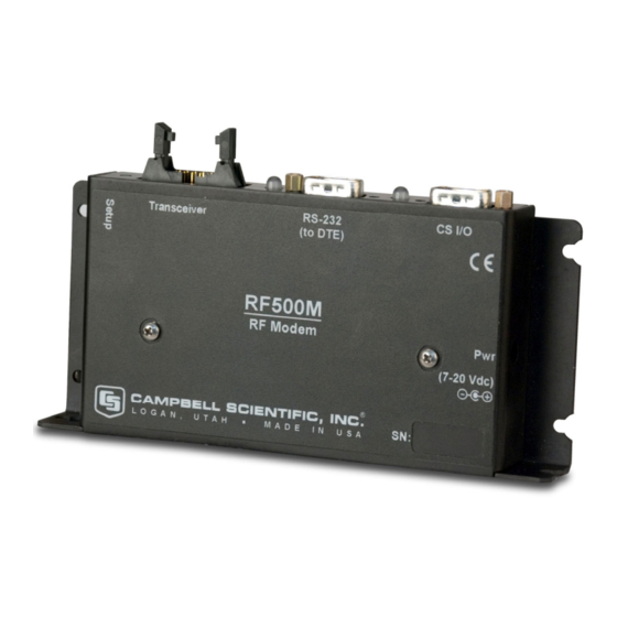
Components 2.1 RF500M Modem The RF500M is an interface between the computer and the radio when used at a base station, and an interface between the radio and the datalogger at a field station. In a repeater station, the RF500M is an interface between two other communication stations. -
Page 8: Specifications
RF500M. 2.1.3 Setting the RF Address Each RF500M, including the one used as the RF base, must have a unique RF Address or RF ID. The RF ID is similar to a phone number. This unique identifier allows the base station to communicate with a specific field station. -
Page 9: Rf500M Connections
The lights can also be used to verify the appropriate power up sequence of the RF500M. View the indicator lights while applying power with the power adapter or connecting the datalogger to the RF500M CS I/O Port with an SC12 cable. The sequence of the lights flashing after connection indicates the power up self-test status. -
Page 10: Rf500M Radio Jumper Location
Section 2. Radiotelemetry Network Components Depending on the radio being used, the appropriate internal jumper must be selected on the RF500M circuit board. There is a set of six jumpers in series located just under the Campbell Scientific, Inc. name and circuit board version number etched on the board. -
Page 11: Digital Radio Description
The RF500M is compatible with digital RS-232 radios such as the DataRadio Integra radio. The digital radios are connected to the RF500M modem with a serial cable between RS-232 ports. Use Device Configuration Utility to configure the RS-232 connection options in the RF500M to work with the digital radio. -
Page 12: Antenna Cables And Connectors
Type-NF (female) for antennas with male receptacles. A Campbell Scientific antenna cable complete with connectors is specified as either COAX NM-L or COAX NF-L. COAX NF-L is a coaxial RG-8A/U cable with a BNC connector on one end and a Type-NF connector on the other. - Page 13 Section 2. Radiotelemetry Network Components FIGURE 2-5. The PD46 Clamp Mount FIGURE 2-6. Type-NM (male), BNC, and Type-NF (female) Connectors TABLE 2-2. Common Antennas and Characteristics VHF or Mounting Antenna Type Cable Gain(dB) Pipe O.D. Type BA1010 Omni Coax NM-L Unity 3/4"...
-
Page 14: Tripods, Towers, Enclosures, And Power Supplies
For the different mounting requirements, Campbell Scientific offers many styles and sizes of tripods and towers. All mounting options available from Campbell Scientific are rugged instrument mounts that provide sturdy support for Campbell Scientific sensors, enclosures, and measurement electronics. 2.4.2 Enclosures Enclosures are needed to keep water and debris from damaging the data acquisition equipment. -
Page 15: Assembling The Radiotelemetry Network
3.2 Configure the RF500M 3.2.1 Device Configuration Utility Device Configuration Utility software is used to configure the RF500M modem. Device Configuration Utility is included with LoggerNet or it can be downloaded for free from the Campbell Scientific web site (http://www.campbellsci.com). - Page 16 Section 3. Assembling the Radiotelemetry Network To configure the RF500M, apply power to the modem, wait for the power-up sequence lights to cycle and then turn off, connect the PC to the RF500M RS- 232 port with a null modem cable, open Device Configuration Utility, highlight the RF500M option in the Device Type list, and click Connect.
-
Page 17: Install Base Station
Once the RF500M has been configured, it is ready to be deployed. 3.2.2 Install Base Station When the RF500M is used in a base station configuration, the PC is attached to the RS-232 port with a null modem cable. If a digital radio is being used on... -
Page 18: Loggernet Setup
3.3 LoggerNet Setup LoggerNet refers to the RF500M as either “RFBase-TD” or “RFRemote-PB” depending on whether the RF500M is used in an RF base configuration or as an RF remote or repeater site. The Setup screen in LoggerNet is used to create a device map, which contains the RF path information. -
Page 19: A Successful Test
Section 3. Assembling the Radiotelemetry Network Remote” then highlight the RF remote to test. Click “Start Test” and wait for the test results. After a successful RF link test, the next step is to attempt communication with the datalogger over the RF link. From the TroubleShooter client choose the “Comm Test”... - Page 20 Section 3. Assembling the Radiotelemetry Network...
-
Page 21: Operation Of The Radiotelemetry Network
COM port, usually listed as ComPort. The next item in the typical communication path is the RFBase-TD to represent the RF500M acting as the RF base station. After the RFBase-TD, each field station RF500M is represented with an RFRemote-PB device in network map. -
Page 22: Automated Data Collection With Loggernet
The RFRemote-PB must have a unique RF Address. The RF Address for the RFRemote-PB must match the address that is entered in the configuration of the RF500M modem. 4.1.3 Automated Data Collection with LoggerNet One feature of LoggerNet is automated data collection. LoggerNet can be setup to call each station based on time. -
Page 23: General Communication - Loggernet Connect Screen
Section 4. Operation of the Radiotelemetry Network FIGURE 4-2. LoggerNet Setup Screen - Schedule Tab 4.1.4 General Communication – LoggerNet Connect Screen General communications include: collect data, send and retrieve programs, monitor measurements in real time, graph real time data, etc. The LoggerNet Connect screen supports these general communication tasks. -
Page 24: Datalogger Initiated Communications
This method of data collection is referred to as One Way Data. With scheduled data collection disabled and LoggerNet running, the RF polling process of the RF500M retrieves data sent from the datalogger to LoggerNet. Over an RF500M network, One Way Data is the most efficient method of data collection. - Page 25 In an RF500M network, the record is sent directly to a buffer in the RF remote and the record is collected during the next RF polling procedure. When LoggerNet receives a One Way Data record, the record is validated and processed.
- Page 26 Section 4. Operation of the Radiotelemetry Network If the RF remote is storing more data in its buffer than can be sent in the defined time window of the polling event, the RF Remote requests more time to send the remaining data. After all RF remotes have had a chance to respond during their defined time windows within the polling event, the RF remote that requested additional time to send more data takes control of the RF medium and takes any additional time necessary to transmit data.
-
Page 27: A. Fundamentals Of Radiotelemetry
Radio waves can be divided into three categories: 1) ground waves, 2) direct waves, and 3) sky waves. All communication with Campbell Scientific's RF networks is done via direct waves. Direct waves travel "line-of-sight" at a maximum distance of approximately 25 miles. -
Page 28: A.2 Antennas
A.3 RF500M Modem The RF500M Modem is the main communication control device in a radiotelemetry network. The RF Modem enables a central base site to communicate with up to 254 different RF stations. -
Page 29: A.4 Transceiver
Appendix A. Fundamentals of Radiotelemetry sequences, sets data to be transferred into data blocks, creates signatures of data blocks, modulates the radio's carrier wave, and stores information on communication quality. The user at the computer is responsible for naming the desired communication path with a setup string. - Page 30 Appendix A. Fundamentals of Radiotelemetry...
-
Page 31: Appendix B. Power Calculations
Appendix B. Power Calculations There must be enough transmission power in any RF link to complete communication. The sources of power are the radio and the antennas. Conversely, power is lost both through the cables (coax loss) and over the distance of communication (path loss). - Page 32 Appendix B. Power Calculations Power Conversion Conversion of Watts to dBm can be done with the following formula. dBm = 10 * Log((Watts)/0.001)
- Page 33 Glossary Antenna - Device for radiating and receiving radio signals. Attenuation - The reduction of an electrical signal without appreciable distortion. Base Station - The destination for accumulated data; where data is received via radio from one or more field stations. Baud Rate - A unit of data transmission speed, normally equal to one bit per second.
- Page 34 Glossary Radio Frequency - The number of cycles per second with which the carrier wave travels, usually specified in Megahertz. Radiotelemetry - Process of transmitting data by radio communication. Radiotelemetry Link - A temporary communication path within a network. Radiotelemetry Network - A group of stations which communicate by radio and are used to indicate or record data.
- Page 36 Campbell Scientific Companies Campbell Scientific, Inc. (CSI) 815 West 1800 North Logan, Utah 84321 UNITED STATES www.campbellsci.com • info@campbellsci.com Campbell Scientific Africa Pty. Ltd. (CSAf) PO Box 2450 Somerset West 7129 SOUTH AFRICA www.csafrica.co.za • cleroux@csafrica.co.za Campbell Scientific Australia Pty. Ltd. (CSA)
Need help?
Do you have a question about the RF500M and is the answer not in the manual?
Questions and answers