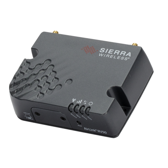
Campbell Sierra Wireless AirLink RV50 Product Manual
4g lte cellular modem
Hide thumbs
Also See for Sierra Wireless AirLink RV50:
- Quick deploy manual (7 pages) ,
- Quick manual (2 pages) ,
- Quick deploy manual (3 pages)
Table of Contents
Advertisement
Advertisement
Table of Contents

Subscribe to Our Youtube Channel
Related Manuals for Campbell Sierra Wireless AirLink RV50


Summary of Contents for Campbell Sierra Wireless AirLink RV50
- Page 1 Revision: 01/2020 Copyright © 2016 – 2020 Campbell Scientific, Inc.
-
Page 2: Limited Warranty
Limited warranty “Products manufactured by CSI are warranted by CSI to be free from defects in materials and workmanship under normal use and service for twelve months from the date of shipment unless otherwise specified in the corresponding product manual. (Product manuals are available for review online at www.campbellsci.com.) Products not manufactured by CSI, but that are resold by CSI, are warranted only to the limits extended by the original manufacturer. - Page 3 Campbell Scientific reserves the right to refuse service on products that were exposed to contaminants that may cause health or safety concerns for our employees.
- Page 4 Periodically (at least yearly) check electrical ground connections. WHILE EVERY ATTEMPT IS MADE TO EMBODY THE HIGHEST DEGREE OF SAFETY IN ALL CAMPBELL SCIENTIFIC PRODUCTS, THE CUSTOMER ASSUMES ALL RISK FROM ANY INJURY RESULTING FROM IMPROPER INSTALLATION, USE, OR MAINTENANCE OF TRIPODS, TOWERS, OR...
-
Page 5: Table Of Contents
1. Introduction 2. Precautions 3. Initial inspection 4. Pre-installation 4.1 Establish cellular service 4.1.1 Campbell Scientific cellular data service 4.1.2 Other service providers 4.2 Install the SIM card 4.3 Konect PakBus Router setup 4.3.1 Get started 4.3.2 Set up Konect PakBus Router 5. - Page 6 Appendix D. Verizon Wireless and AT&T D.1 Verizon Wireless D.2 AT&T Appendix E. Regulatory information E.1 Important information for North American users E.2 RF exposure E.3 EU E.4 Declaration of conformity E.5 RoHS compliance Campbell Scientific regional offices Table of Contents - v...
-
Page 7: Introduction
Communications) and CDMA (Code Division Multiple Access) networks. The modem is accessed through the Internet using TCP/IP communications protocol. Use of the RV50(X) requires a VerizonLTE or AT&T® HSPA+/LTE business account or an equivalent account from Campbell Scientific or another service provider. For more information, Establish cellular service (p. 3) NOTE: The RV50 also supports Verizon®... -
Page 8: Precautions
Upon receipt of the RV50(X), inspect the package and contents for damage. File any damage claims with the shipping company. Immediately check package contents against the shipping documentation. Contact Campbell Scientific about any discrepancies. RV50(X) Sierra Wireless AirLink® 4G LTE Cellular Modem... -
Page 9: Pre-Installation
T-Mobile, Vodafone, Telstra, and over 600 other providers worldwide. When this cellular service is purchased with the module, the module will come pre-provisioned with the required SIM card and APN. If you have already purchased the RV50(X), call Campbell Scientific to set up service. 4.1.2 Other service providers While using Campbell Scientific is the simplest way to obtain cellular data service for your module, you can go directly to a provider. -
Page 10: Install The Sim Card
This does not apply to Campbell Scientific cellular data services. 4.2 Install the SIM card NOTE: If you purchased cellular service from Campbell Scientific with the module, it will come with the SIM (Subscriber Identity Module) card already installed. Proceed to Konect PakBus Router setup (p. -
Page 11: Konect Pakbus Router Setup
FIGURE 4-1. SIM card installation 4.3 Konect PakBus Router setup For better security, we recommend using Konect PakBus® Router with a private dynamic IP address. This method allows only incoming PakBus communication. No other incoming communication is supported. However, all forms of outbound communication from the data logger are supported, including but not limited to PakBus, email, and ftp. -
Page 12: Set Up Konect Pakbus Router
Open a web browser and go to www.konectgds.com. First-time users need to create a free account. After you submit your information, you will receive two emails up to five minutes apart. One email will contain a Passport ID and the other your Password. - Page 13 2. Click devices and services on the command bar to the left and select Redeem PakBus Router Code. Enter your complimentary Router Code found on the included card with your cellular-enabled device and click Submit. 3. The next screen shows the assigned DNS address and Port for the router. An optional TCP Password may be entered for additional security, and you must select a unique PakBus Address for your data logger.
-
Page 14: Quickstart
The Provisioning Report received with your Cellular Data Service shows whether the module was configured with a private dynamic or public static IP address. See the following figures for examples of Campbell Scientific Provisioning Reports. Other cellular providers should provide similar information. - Page 15 One sticker will show the module phone number and data plan. The second sticker will show the static IP address. Campbell Scientific cellular modules configured with a private dynamic IP address will have one sticker on the module. It will show the module phone number and data plan.
-
Page 16: Modules Using Konect Pakbus Router (Private Dynamic Ip)
FIGURE 5-3. Module with public static IP address FIGURE 5-4. Module with private dynamic IP address 5.1 Modules using Konect PakBus Router (private dynamic IP) 5.1.1 Configure RV50(X) 1. Download the collection of RV50(X) configuration templates from www.campbellsci.com/downloads and run the executable downloaded. 2. - Page 17 NOTE: If Campbell Scientific did not provision the RV50(X) or it does not automatically connect to the network, you may need to to confirm or enter your APN information. Follow steps 6 through 8 to WAN/Cellular > SIM Slot 1 Configuration > Network Credentials >...
-
Page 18: Enabling Ppp Mode
10. Click the Template button in the ACEmanager toolbar. A template application window will appear. Browse to and upload one of the configuration templates downloaded from Campbell Scientific. Template Files Template File Name Description Default configuration with RS-232 at 115200 baud and RV50_115200.xml... - Page 19 On the Com Ports Settings tab, select the COMPort where the module is connected; this is generally RS-232. Change the Baud Rate to 115200 Fixed. On the PPP tab select the Config/Port Used where the modem is connected. This is the same as was selected on the Com Ports Settings tab.
-
Page 20: Set Up Loggernet
On the Network Services tab, in the PakBus/TCP Clients box, type the DNS address and Port number noted during the Set up Konect PakBus Router (p. 6) step. Apply to save your changes. 5.1.3 Set up LoggerNet The LoggerNet Network Map is configured from the LoggerNet Setup screen. NOTE: Setup has two options, EZ (simplified) and Standard. - Page 21 4. Select the IPPort in the Network Map. Enter the Konect PakBus Router DNS address and port number as noted in the Konect PakBus Router setup. The DNS address and port number are input in the Internet IP Address field separated by a colon. For example, axanar.konectgds.com:pppp where pppp is the port number.
- Page 22 6. For PakBus data loggers, select the pbRouter in the Network Map and set the PakBus Address to 4070. 7. For PakBus data loggers, select the data logger in the Network Map and set the PakBus Address to match that of the data logger (default address in the data logger is 1). If a PakBus Encryption Key was entered during data logger setup, also enter it here.
-
Page 23: Test The Connection
5.1.4 Test the connection After the Network Map has been configured, test the cellular connection by using the Connect screen as shown in the following image. Click on the appropriate station and click Connect to initiate a call to the data logger. TIP: The connection time is subject to many external factors. - Page 24 Network LED. NOTE: If Campbell Scientific did not provision the RV50(X) or it does not automatically connect to the network, you may need to to confirm or enter your APN information. Follow steps 6 through 8 to WAN/Cellular > SIM Slot 1 Configuration > Network Credentials >...
- Page 25 PING tool to ping an Internet server, such as www.campbellsci.com. 10. Click the Template button in the ACEmanager toolbar. A template application window will appear. Browse to and upload one of the configuration templates downloaded from Campbell Scientific. Template Files Template File Name...
-
Page 26: Enabling Ppp Mode
11. Reboot the RV50(X) after successfully applying the configuration template. You can do this by clicking the Reboot button on the ACEmanager toolbar, by momentarily pressing the Reset button (2 sec), or by temporarily removing power from the RV50(X). 5.2.2 Enabling PPP mode Launch the Device Configuration Utility . -
Page 27: Set Up Loggernet
On the PPP tab select the Config/Port Used where the modem is connected. This is the same as was selected on the Com Ports Settings tab. Set Modem Dial String to AT\APPP. Apply to save your changes. 5.2.3 Set up LoggerNet The LoggerNet Network Map is configured from the LoggerNet Setup screen. - Page 28 4. Select the IPPort in the Network Map. Enter the RV50(X) IP address and port number. The IP address and port number are input in the Internet IP Address field separated by a colon. Preceding zeros are not entered in the Internet IP Address (for example, 070.218.074.247 is entered as 70.218.74.247).
-
Page 29: Test The Connection
6. For PakBus data loggers, select the data logger in the Network Map and set the PakBus Address to match that of the data logger (default address in the data logger is 1). If a PakBus Encryption Key was entered during data logger setup, also enter it here. Click Apply to save the changes. -
Page 30: Specifications
If the call is successful, the connectors at the bottom of the screen will come together and clock information from the data logger will be displayed in the Station Date/Time field. If the connection fails, a Communications Failure message will be displayed. 6. -
Page 31: Installation
RF Connectors 3 SMA antenna connectors (primary, diversity & GPS) Active antenna support Power Operating Voltage: 7 to 36 Vdc Typical Enable/Ignition Sense Line Low: 1 mA @ 12V Typical Idle: 65 to 95 mA @ 12V, depending on configuration Typical Active: 250 to 300 mA @ 12V, depending on configuration Size Dimensions: 119 x 34 x 94 mm (4.69 x 1.34 x 3.7 in) -
Page 32: Base Station Requirements
7.3.2 Module power connections 7.3.3 Antenna connections 7.4 Hardware and software setup 7.1 Base station requirements A computer running Campbell Scientific LoggerNet software with access to the Internet is needed. 7.2 Data logger site equipment RV50(X) module with power cable (included with module) Data logger —... - Page 33 Ethernet cable - connects the module to CR6 or NLxxx. Antenna — the following antennas are available from Campbell Scientific. Contact Campbell Scientific for help in determining the best antennas for your application. 2 dBd 4G/3G Omnidirectional Antenna: An omnidirectional antenna with mounting bracket that is ideally suited for use with 4G and 3G cellular gateways.
-
Page 34: Rv50(X) Mounting Kit
intended for use inside the enclosure. Please note that the backplate of the enclosure is a grounded plane. If it is interposed between the antenna and the cell tower, it may attenuate the strength of the transmission signal. Simply turning the enclosure 90 to 180 degrees on its mounting mast may solve weak transmission issues. -
Page 35: Mounting The Rv50(X) On Edge To The Backplate
7.2.1.2 Mounting the RV50(X) on edge to the backplate Use two of the included pan-head Phillips screws to mount the RV50(X) to the bracket. Then use two of the included pan-head Phillips screws to mount the bracket to the backplate. 7.3 Wiring and connections This section explains how to connect the module for different communications methods. -
Page 36: Module Communications Connections
7.3.1 Module communications connections RS-232 connection using a null module cable Null module Cable, is used to connect the module to the CR3000, CR800 series, CR2XX, CR300 series, CR1000, CR1000X series or CR5000 RS-232 port. RS-232 connection using a CPI/RS-232 cable RS-232/CPI RJ45 to DB9 Male DTE, is used to connect the module to the CR6 or GRANITE 6/9/10. -
Page 37: Module Power Connections
module using the serial cable supplied with the SC105. The SC105 is attached to the data logger CS I/O port using the SC12 cable supplied with the SC105. 7.3.2 Module power connections Connect the power cable leads to a power supply. Wire Color Function Connect To... - Page 38 Antenna diversity, also called space diversity, is a scheme that uses two or more antennas to improve the quality and reliability of a wireless link. Often, especially in urban and indoor environments, there is no clear line of sight between transmitter and receiver. Instead, the signal is reflected along multiple paths before finally being received.
-
Page 39: Hardware And Software Setup
(p. 8) for more information. 8. Operation and maintenance 8.1 Ports The RS-232 port is the main port used with Campbell Scientific dataloggers. Its function is described throughout this manual. The USB port is not used in Campbell Scientific applications. -
Page 40: Led Indicator Lights
8.2 LED indicator lights When your RV50(X) is connected to power and an antenna, there is a specific pattern to the lights to indicate its operation mode as described in the following table: Table 8-1: LED indicator lights Color / Description LED Power Saving Mode Pattern... - Page 41 Table 8-1: LED indicator lights Color / Description LED Power Saving Mode Pattern NOTE: The quality of the signal strength is measured using the appropriate parameters for the radio technology in use. Solid Connected to an LTE network Green Connected to a 3G network Solid Amber or 2G network (RV50 only)
-
Page 42: Signal Strength
Table 8-1: LED indicator lights Color / Description LED Power Saving Mode Pattern Green Radio module reconfiguration/firmware update or Network Operator Switching is in progress. chase Amber Firmware update is in progress. chase Solid Firmware update complete (all LEDs are amber except the Power LED) Amber Red LED The modem is in Recovery mode. -
Page 43: Rebooting The Rv50(X)
8.4 Rebooting the RV50(X) There are two methods to reboot the RV50(X): On the RV50(X), press the Reset button for 1–5 seconds. (Release the button when the Power LED flashes green.) In ACEmanager, click the Reboot button on the toolbar. 8.5 Reset the RV50(X) to factory default settings There are two methods to reset the RV50(X) to the factory default settings:... -
Page 44: Attributions
AirLink and Sierra Wireless are registered trademarks of Sierra Wireless. AT&T is a trademark of AT&T Intellectual Property. Bell is a registered trademark of Bell Canada. PakBus is a registered trademark of Campbell Scientific, Inc. Rogers is a trademark of Rogers Communications. Sprint is a registered trademark of Sprint. -
Page 45: Appendix A. Acemanager And Template Files
Appendix A. ACEManager and template files ACEmanager along with template files can be used to set up the RV50(X) in PPP or serial server mode. To enable PPP mode, see Enabling PPP mode (p. 12). ACEmanager is accessed via a web browser. For initial setup or troubleshooting with a direct (cabled) connection, connect a standard Ethernet (RJ45) cable between the Ethernet port on the computer and that on the module. -
Page 46: Cr5000, And Granite
After entering the password and pressing enter (or clicking Log In), the following status screen is displayed: RV50 template files from the Campbell Scientific website (www.campbellsci.com/downloads) are used to configure the RV50(X) module using ACEmanager. Template Files Template File Name... - Page 47 Click the Template menu in the top right of the screen. When prompted for a template file name, select RV50_115200.xml or RV50_9600.xml. The following screen shows the settings under the Serial tab after the 115200 baud template file has been loaded. Click on WAN/Cellular for the following screen: Enter the APN as shown in the screen above.
- Page 48 Click Reboot to restart the module. Alternately, reset the module by pressing Reset on the front of the module or by removing power from the module. Click Logout to terminate communications with the module. WARNING: Unless you Apply the commands, the changes made will not be saved in the module. For most commands, you must reboot the module for the newly written values to take effect.
-
Page 49: Appendix B. Controlling Power To The Rv50(X)
Appendix B. Controlling power to the RV50(X) The RV50 uses considerably more power than the data logger. Therefore, it may be necessary to use the data logger to control power to the RV50. The following program examples show how to control power to the RV50 using the switched 12V (SW12V) terminal on the data logger. - Page 50 CRBasic Example 1: Turn RV50(X) ON and OFF under data logger control If TimeIsBetween AND TimeIsBetween Then (9,17,24,Hr) (0,15,60,Min) ModuleState=True PPPOpen SW12 Else ModuleState=False PPPClose SW12 EndIf 'Always turn OFF RV50(X) if battery drops below 11.5 volts BattV<11.5 Then 'Set RV50(X) power to the state of 'ModuleState' variable SW12 EndIf 'Call Data Tables and Store Data...
-
Page 51: Appendix C. Using The Rv50(X) Ethernet Port
Appendix C. Using the RV50(X) Ethernet port The RV50(X) Ethernet port can be used to communicate with IP-enabled devices such as data loggers and IP cameras. However, the use of Ethernet communication increases the total system current demand (the module and the device you are connecting to) by several milliamps as compared to the use of serial communications. - Page 52 For this example, a static Ethernet IP Address, Default Gateway, Ethernet Subnet Mask, and Ethernet Name Servers are configured in the CR1000 as shown in the figure below. The example CR1000 Ethernet IP address of 192.168.13.50 is the same address used in the RV50(X) port forwarding configured previously.
-
Page 53: Appendix D. Verizon Wireless And At&T
Appendix D. Verizon Wireless and AT&T NOTE: Campbell Scientific can provide Verizon Wireless or AT&T service. This is the simplest way to set up your module on the Verizon Wireless or AT&T network. See Campbell Scientific cellular data service (p. 3). -
Page 54: At&T
AT&T 4G LTE CAT-1 coverage at the data logger site. For a coverage map refer to: www.att.com/maps/wireless-coverage.html. AT&T 4G LTE private dynamic IP account in conjunction with Campbell Scientific’s Konect Router Service. (An AT&T 4G LTE static unrestricted IP account can also be used. However, AT&T charges $3/month/device for the static IP account.) -
Page 55: Appendix E. Regulatory Information
Appendix E. Regulatory information This information provided by Sierra Wireless®. E.1 Important information for North American users This equipment has been tested and found to comply with the limits for a Class A digital device, pursuant to part 15 of the FCC Rules. These limits are designed to provide reasonable protection against harmful interference when the equipment is operated in a commercial environment. -
Page 56: Declaration Of Conformity
Device Frequency Band Gain Cellular Band 4.0 dBi PCS Band 3.0 dBi Band 2 3.0 dBi AirLink RV50 (N7NMC7355 Band 4 4.0 dBi 2417C-MC7355) Band 13 4.0 dBi Band 17 4.0 dBi Band 25 3.0 dBi AirLink RV50(X) Bands 2, 4, 5, 12, 13, 25, 26 6.0 dBi (N7NMC7455 Band 7, 41... -
Page 57: Rohs Compliance
E.5 RoHS compliance RV50(X) Sierra Wireless AirLink® 4G LTE Cellular Modem... -
Page 58: Campbell Scientific Regional Offices
INFO Global Sales & Support Network A worldwide network to help meet your needs Australia France Thailand Garbutt, QLD Australia Vincennes, France Bangkok, Thailand Location: Location: Location: Phone: 61.7.4401.7700 Phone: 0033.0.1.56.45.15.20 Phone: 66.2.719.3399 info@campbellsci.com.au info@campbellsci.fr info@campbellsci.asia Email: Email: Email: www.campbellsci.com.au www.campbellsci.fr www.campbellsci.asia Website:...
Need help?
Do you have a question about the Sierra Wireless AirLink RV50 and is the answer not in the manual?
Questions and answers