Table of Contents
Advertisement
Advertisement
Table of Contents

Related Manuals for Sur-Gard SG System II


Summary of Contents for Sur-Gard SG System II
- Page 1 Sur-Gard System II Single Line Network Receiver Operating Manual version 2.0 WARNING: This manual contains information on limitations regarding product use and function and information on the limitations as to liability of the manufacturer. The entire manual should be carefully read.
- Page 2 GENERAL DESCRIPTION of the EQUIPMENT and CLASSIFICATION. SYSTEM II - SAFETY INSTRUCTIONS building structure before operation; all wiring and installation The SYSTEM II equipment is a CLASS 1, DESK-TOP (MOV- shall be in accordance with electrical codes acceptable to the ABLE) or RACK-MOUNTED (FIXED - STATIONARY), authorities that have jurisdiction where the equipment is EQUIPMENT, PLUGGABLE TYPE A using a DETACHABLE...
-
Page 3: Table Of Contents
Table of Contents Section 1 - Introduction ........1 Option [014]: Receiver Number ........13 Option [015]: Printer Test ..........13 1.1 Features .............. 1 Option [020]: Mask UPS AC ........13 1.2 Software Compatibility........1 Option [021]: Mask UPS BAT..........13 1.3 Approvals ............ -
Page 4: Limited Warranty
WARNING tion activity inside or outside the premises. The testing should include all sensing devices, keypads, Please Read Carefully consoles, alarm indicating devices and any other operational devices that are part of the system. Not e to Instal lers - Security and Insurance Regardless of its capabilities, an alarm system is not a substitute for property or life insurance. -
Page 5: Section 1 - Introduction
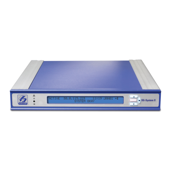
Section 1 - Introduction 1.1 Features The SG-System II is a single line network receiver intended for remote monitoring of commercial fire and burglary systems. The system can be configured for “desktop stand-alone” operation (vertical stacking of up to 4 systems) or rack mounting. The SG-System II can monitor up to 1536 accounts including 512 supervised accounts. - Page 6 This equipment shall be installed in accordance with the requirements of NFPA72, NFPA70, and the authority having jurisdiction. The Equipment is ULC listed for active communication channel security level A4 when used in conjunction with compatible communicators, ULC listed for the same level of line security (DSC Models T-Link TL250, T-Link TL300, TL265GS, GS2065, TL260GS, GS2060). Compatible Communicators: •...
-
Page 7: Specifications
1.4 Specifications Electrical • Input Voltage ..............................100-240VAC, 50-60Hz. • Input Current ...................................0.7A (Max) • Backup Power Supply ..........................External UPS (not supplied) Environmental • Temperature................................32 - 122°F (0-50°C) • Humidity ..............................93%RH, Non Condensing Dimensions • Width ..................................12in. (305mm) • Length .................................. 12.25in. (311mm) •... -
Page 8: Section 2 - Installation
Section 2 - Installation 2.1 Controls and Indicators Controls and Indicators Figure 2: SG-System II Table 7: SG-System II Front and Rear Panel Descriptions Item No. Indicator/ Control/ Connector State/Pin Description NETWORK Green LED Network Absent Network Present Follows the network interface that receives T-Link signals. TROUBLE Orange LED Indicates any System Trouble not related to network or alarm (Note that the LCD backlight will override the programmed colour and change to Yellow). - Page 9 Table 7: SG-System II Front and Rear Panel Descriptions Item No. Indicator/ Control/ Connector State/Pin Description ACK Interface Button/LED FLASHING Indicates unit is in Manual Mode and waiting for acknowledgement. There are no alarm events requiring acknowledgement. The ACK button is used to acknowledge an alarm event in Manual Mode. It cannot acknowledge all alarms with one press, but must be pressed for each individual alarm.
-
Page 10: Set Up And Testing
2.2 Set Up and Testing DSC recommends testing the receiver before actual installation. Becoming familiar with the connections and setup of the unit on the workbench will make final installation simpler. The following items are required: • IEC Power Supply cord •... -
Page 11: Section 3 - Operation/Operating Modes
Section 3 - Operation/Operating Modes There are two main categories of operating modes, Native and Program Modes. 3.1 Active Mode Active Mode is the normal operating mode. The SG-System II is in Active mode when any of the Automation Ports are present and respond- ing to signals. -
Page 12: System Functions Menu
Select the Exit Menu and press the ENTER button. You will return to the View or Change Options level. Pressing the UP and DOWN buttons simul- taneously - regardless of your place within View or Change Options - will take you to the Top Level menu. View Printer Buffer The bottom line of the LCD is cleared when View Printer Buffer is entered. -
Page 13: Miscellaneous Led Indicators
3.3.5 Miscellaneous LED Indicators View Trouble To enter View Trouble, the unit must first be in Active mode or Manual mode, and have no events to be acknowledged in Manual mode. Press the UP and DOWN buttons simultaneously to enter View Trouble. Once there, the UP and DOWN buttons can be used to review the list of trou- bles. -
Page 14: Section 4 - System Options
Section 4 - System Options 4.1 System Option Index Page Page Option [001]: LAN IP Address......... 11 Option [021]: Mask UPS BAT..........13 Option [002]: LAN Subnet Mask Address....... 11 Option [024]: Mask SG TCP/IP........13 Option [003]: LAN Gateway...........11 Option [025]: Mask SG Serial .........14 Option [004]: Auto Update Time and Date.... -
Page 15: System Options
4.2 System Options Option [001]: LAN IP Address Default (10.0.7.100) Enter the IP address of the SG-System II. The IP address must be entered as a dotted decimal number (e.g. 255.255.001.000). Each three-digit segment of the IP address must be within a valid range of 000 to 255. NOTE: The SG-System II must be restarted for these changes to take effect. -
Page 16: Option [009]: Automation Parity
Option [009]: Automation Parity Default (0) This option determines the parity of serial port 1. Table 8: Automation Parity Value Degree of Parity No parity Odd parity Even parity NOTE: The number of stop bits can not be changed and will always be 2. NOTE: The SG-System II must be restarted for these changes to take effect. -
Page 17: Option [013]: Buzzer Tone
Option [013]: Buzzer Tone Default (00) A tone will sound when the SG-System II, having received an alarm, is unable to forward the alarm message to either the Serial or TCP/IP automa- tion paths (while in Manual mode). You are able to manipulate this tone via Option [013]. The tone generated will continue to pulse until all unacknowledgedevents have been acknowledged by the user;... -
Page 18: Option [025]: Mask Sg Serial
Option [025]: Mask SG Serial Default (OFF) Use this option to enable the SG Serial trouble mask. If enabled, trouble conditions are not reported. OFF - Condition reported ON - Condition not reported (masked) UL864 Programming Requirements on page 2 Option [028]: Mask TCP Printer Default (OFF) Use this option to enable the TCP Printer trouble mask. - Page 19 Figure 4: Loop (00), Automatic IP Fallback (04) Power Up / Restart Automatic Falback mode (4) Manual Re-start Poll from Console SG-System I TCP Automation (Reset Fallback) Port Active? Manual Re-start \SG-System I from Console Serial 1 Port (Reset Fallback) Active? Figure 5: Fallback (01) Power Up /...
-
Page 20: Option [030]: Printer Mode
Option [030]: Printer Mode Default (LOOP) You can configure this option with an approach similar to the automation outputs of Option [02F] above, except that Fallback (01) and Auto- matic IP Fallback (04) are not available. The acceptable value is Loop (00). Note that Loop (00) transmits printer messages to each port in turn. The first port to respond will be used to process subsequent printer messages until it is no longer able to do so, at which point the next port in the loop will be employed. -
Page 21: Option [03B]: Last Message On
Option [03B]: Last Message On Default (Off) When enabled, this option displays the most recent printer message on the lower line of the unit LCD. It will remain there until a new printer message replaces it. The automation condition - e.g. mode (Active / Manual) or slot (all / TCP / Serial) - does not have any effect on this fea- ture.Option [03C]: LCD Backlight Colour Default (Cyan) You can use this option to select the LCD backlight colour. -
Page 22: Option [043]: System Protocol Id
Option [043]: System Protocol ID Default (0) Use this option to determine the format that the system will use to deliver its internal messages. Automation software delivered since the year 2000 is more likely to take the ‘S’ value and to provide detailed information on events that have been generated. Older automation software will require that you input the ‘0’... -
Page 23: Ip Option Index
Section 5 - IP Options 5.1 IP Option Index Page Page Option [101]: IP Address ..........19 Option [11E]: Mask Unknown Account......21 Option [105]: Subnet Mask..........19 Option [11F]: Mask Supervised Acc Exceeded ....21 Option [10F]: Receiver Number ........20 Option [120]: Mask Transmitter Deleted......21 Option [110]: Line Card Number - Table 1 ..... -
Page 24: Option [110]: Line Card Number - Table 1
Option [10F]: Receiver Number Default: [01] The receiver number is used for sending signals to the central station software. Refer to the manuals for any central station automation software being used to determine if there are any special requirements for this number. Also, ensure that there are no duplicate receiver numbers used. Option [110]: Line Card Number - Table 1 Default (03) Use this option to provide each SG-System II line card with an identification code. -
Page 25: Option [11F]: Mask Supervised Acc Exceeded
Option [11E]: Mask Unknown Account Default (OFF) Use this option to enable or disable the reporting of an unknown account report condition when the SG-System II receiver determines that it is from an invalid account (not in the Account table). The default value is appropriate in most situations, save those when a number unknown accounts are expected to be reported due to, for example, system testing or maintenance. -
Page 26: Option [147]: Sim Id Output
(up to 10 digits, depending on the status of Option [146]) and the SIM card number (21 digits). The automation soft- ware must support the protocol via the Sur-Gard output format for this option to work. -
Page 27: Appendix A - Events And Messages
Appendix A - Events and Messages Description/Event Automation message Printer message TCP/IP Printer Failure 001000[#0000|NVZ0100] 01-000-0000-NVZ0100-TCP/IP Printer Failed TCP/IP Printer Restoral 001000[#0000|NVY0100] 01-000-0000-NVY0100-TCP/IP Printer Restored Parallel Printer Failure 001000[#0000|NVZ0101] 01-000-0000-NVZ0101-Parallel Printer Failed Parallel Printer Restoral 001000[#0000|NVY0101] 01-000-0000-NVY0101-Parallel Printer Restored Serial Printer Failure 001000[#0000|NVZ0K102] 01-000-0000-NVZ0102-Serial Printer Failed Serial Printer Restoral... - Page 28 Description/Event Automation message Printer message Invalid Report (where IP is transmitters IP, and X is the 001001[#XXXXXXXXXX|NYN* 01-001-XXXXXXXXXX-YN-*Invalid Report/Possible transmitters account) IP.IP.IP.IP *] Compromise Attempt IP.IP.IP.IP* Possible Compromise Attempt(where IP is transmitters 001001[#XXXXXXXXXX|NPC* 01-001-XXXXXXXXXX-PC-Possible Compromise IP, and X is the transmitters account) IP.IP.IP.IP *] Attempt Max Accounts Exceeded (where IP is transmitters IP, and...
-
Page 29: Appendix B - Ports
Appendix B - Ports Parallel Printer Port The parallel printer port sends events to the local printer (DB25 Female). NOTE: Maximum cable length is 1.8m (6ft). Longer cables may impair performance. Figure 7: Parallel Printer Port Table 16: Parallel Printer Port Pinouts Pin no (DB25) Signal name Direction... - Page 30 RS232 Serial Automation The serial automation port is used to send automation signals to the automation computer using the Sur-Gard Automation protocol. Only the serial port requires RX, TX, and GRD. Table 17: Serial Printer Port RJ45 Pin no Description in relation to SG-System II...
- Page 31 IMPORTANT - READ CAREFULLY: DSC Software purchased with or without Products and Components is copyrighted and is purchased under the following license terms: •This End-User License Agreement (“EULA”) is a legal agreement between You (the (f) Termination - Without prejudice to any other rights, DSC may terminate this EULA if company, individual or entity who acquired the Software and any related Hardware) You fail to comply with the terms and conditions of this EULA.
- Page 32 ©2009 Digital Security Controls Toronto, Canada • www.dsc.com 29007174R003 Sales: 1-888-888-7838 Tech. Support (Canada & USA): 1-800-503-5869 Printed in Canada...
Need help?
Do you have a question about the SG System II and is the answer not in the manual?
Questions and answers