Table of Contents
Advertisement
Quick Links
Advertisement
Table of Contents

Related Manuals for Sur-Gard System I


Summary of Contents for Sur-Gard System I
- Page 1 Sur-Gard System I Operating Manual version 1.0 WARNING: This manual contains information regarding product use and function, in addition to manufacturer lia- bility and restrictions pertaining to it. The entire manual should be read carefully...
-
Page 2: Safety Considerations
VICE PERSONS ONLY. [person having appropriate technical training and experience necessary to be aware of hazards to which that person may be exposed in performing a task and of measures to minimize the risks to that person or other persons]. The equipment SG-SYSTEM I shall be installed in RESTRICTED ACCESS LOCATIONS within an environment that provides the Pollution Degree max 2, and over-voltages category II –... - Page 3 Incidence of Harm If this equipment SG-SYSTEM I causes harm to the telephone network, the telephone company will notify you in advance that temporary discontinu- ance of service may be required. But if advance notice is not practical, the Telephone Company will notify the customer as soon as possible. Also, you will be advised of your right to file a complaint with the FCC if you believe it is necessary.
-
Page 4: Limited Warranty
installation is depicted in the figure below. If you have any questions concerning these instructions, you should consult your telephone company or a qualified installer about installing the RJ-31X jack and alarm dialling equipment for you. Customer Premises Equipment and Wiring Network Service Provider's... - Page 5 To obtain service under this warranty, please return the item(s) in question to the point of purchase. All authorized distributors and dealers have a war- ranty program. Anyone returning goods to Digital Security Controls must first obtain an authorization number. Digital Security Controls will not accept any shipment whatsoever for which prior authorization has not been obtained.
- Page 6 WARNING Please Read Carefully Note to Installers This warning contains vital information. As the only individual in contact with system users, it is your responsibility to bring each item in this warning to the attention of the users of this system. System Failures This system has been carefully designed to be as effective as possible.
- Page 7 Warning Devices Warning devices such as sirens, bells, horns, or strobes may not warn people or waken someone sleeping if there is an intervening wall or door. If warning devices are located on a different level of the residence or premise, then it is less likely that the occupants will be alerted or awakened. Audi- ble warning devices may be interfered with by other noise sources such as stereos, radios, televisions, air conditioners or other appliances, or passing traffic.
-
Page 8: Ip Options
make any changes or modifications to the Software, without the written permission of an officer of DSC. You may not remove any proprietary notices, marks or labels from the Software Product. You shall institute reasonable measures to ensure compliance with the terms and conditions of this EULA. (b)Separation of Components - The SOFTWARE PRODUCT is licensed as a single product. - Page 9 ASSOCIATED EQUIPMENT, COST OF CAPITAL, COST OF SUBSTITUTE OR REPLACEMENT EQUIPMENT, FACILITIES OR SERVICES, DOWN TIME, PURCHASERS TIME, THE CLAIMS OF THIRD PARTIES, INCLUDING CUSTOMERS, AND INJURY TO PROPERTY. WARNING: DSC recommends that the entire system be completely tested on a regular basis. However, despite frequent testing, and due to, but not limited to, criminal tampering or electrical disruption, it is possible for this SOFTWARE PRODUCT to fail to perform as expected.
-
Page 10: Table Of Contents
Software Compatibility ..........................9 Approvals ...............................10 Industry Approvals ............................10 UL864 Programming Requirements ..........................10 For UL and ULC listed applications the following UL/ULC listed printers can be used with the System I: .....11 Specifications ............................12 Electrical ..................................12 Environmental ................................12 Dimensions ..................................12 Ethernet Interfaces ...............................12... - Page 11 View Trouble ................................26 Trouble List ..................................27 View Network / Watchdog ............................27 View Status ..................................27 Chapter 4 - Options: System ...................28 System Option Index ..........................29 Steps required to access an option and change its setting or value ............29 System Options ............................30 Option 001: LAN IP Address ............................30 Option 002: LAN Subnet Mask Address ........................30 Option 003: LAN Gateway ............................30...
- Page 12 Static Options ............................46 Option 101: Line Card Number ...........................46 Option 104: Two-Way Activation Time ........................46 Option 105: Pre-H.S. Duration ............................47 Option 109: First Ring Length .............................47 Option 10D: Ring Select.............................. 47 Option 10E: Backup Line Option ..........................47 Option 111: Hook Flash Enable ...........................48 Option 112: Caller Source ID ............................48 Option 113: Caller Source to SG Automation ......................49 Option 114: Caller Source to Printer ...........................49...
- Page 13 Option 198: 3/1 Extended ............................70 Option 199: Ademco Express ............................71 Option 19A: Error Counter ............................71 Option 19B: Echo Canceller ............................71 Option 19C: Acron RS-232 ............................71 Option 19D: Modem II RS-232 ...........................72 Option 19E: Scantronics Select ...........................72 Option 19F: Ademco High Speed RS-232 ........................72 Option 1A0: 11-/12-Digit DTMF (Acron, Scantronics, or Scancom 433) ..............73 Option 1A1: FBI RS-232 .............................74 Option 1A2: Digit Replace ............................74...
- Page 14 Appendix D - Printer Words .................102 Appendix E - Profiles ....................106...
- Page 15 Introduction In This Chapter... Features on page 9 Software Compatibility on page 9 Approvals on page 10 Specifications on page 12 Out of Box on page 12...
-
Page 16: Chapter 1 - Introduction
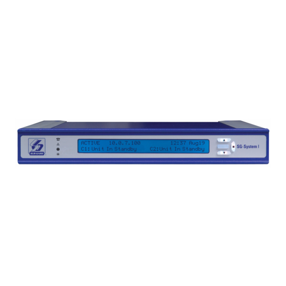
Features The SG-System I is a dual phone line / IP network receiver intended for the remote monitoring of residential / commercial fire and burglary alarm systems. The system can be configured for desktop stand-alone operation (vertical stacking of up to 4 systems) or rack mounting (see Note below). -
Page 17: Approvals
CHAPTER ONE - INTRODUCTION Approvals Industry Approvals The System I meets the following standards: • UL 1610 Central Station Burglar Alarm Units • UL 864 Standard for Fire Alarm System Control Units and Accessories • UL 1635 Digital Alarm Communicator System Units •... -
Page 18: For Ul And Ulc Listed Applications The Following Ul/Ulc Listed Printers Can Be Used With The System I
Option 31D: Mask Invalid Report ON/OFF Option 31E: Mask Unknown Account ON/OFF Option 31F: Mask Supervised Acc Exceeded ON/OFF For UL and ULC listed applications the following UL/ULC listed printers can be used with the System I: Parallel Printers • Seiko DPU-414 Serial Printers... -
Page 19: Specifications
POTS ......................................500 events IP ......................................512 events System ......................................50 events Out of Box Verify that you have received the following: SG-System I SG-System I Receiver ..................................Qty 1 SG-Systems Console Software CD ..............................Qty 1 SG-System I Quick Install Guide ..............................Qty 1... -
Page 20: Sg-System Rackmount Kit (Optional) - Required For Ul/Ulc Listed Installations
CHAPTER ONE - INTRODUCTION Height-Adjustable Rubber Feet (front) ..............................Qty 2 Rubber Feet (rear) ....................................Qty 2 SG-System Rackmount Kit (Optional) - required for UL/ULC Listed Installations Brackets ......................................Qty 2 Rails (Mounting) ....................................Qty 4 Screws .......................................Qty 8 Quick Install Sheet .....................................Qty 1 Additional Equipment Required (Not Supplied) IEC Power Line Cord ..................................Qty 1 CAT-5 Ethernet Cable for Network Interface Port or USB Cable for Console Communication ............Qty 1... -
Page 21: Chapter 2 - Installation
Installation In This Chapter... Controls and Indicators on page 15 Set Up and Testing on page 18... -
Page 22: Controls And Indicators
CHAPTER TWO - INSTALLATION Controls and Indicators Figure 2: Controls and Indicators Table 3: SG-System I Front and Rear Panel Descriptions Item Indicator/ Control/ State/Pin Description Connector TELEPHONE Red Both Telphone Lines are Present. At least One Telephone Line is Absent. - Page 23 CHAPTER TWO - INSTALLATION Table 3: SG-System I Front and Rear Panel Descriptions Item Indicator/ Control/ State/Pin Description Connector LCD Display 40x2 character LCD display. Top line displays current Operating Mode. Bottom line displays Trouble or received messages in Manual mode.
- Page 24 *Rx is the relay number; as a rule, these outputs are open connections USB Port USB Type B USB Type B. The USB port on SG System I is used to connect with a Windows host running the SG-Systems Console Software. Other operating systems are not supported.
-
Page 25: Set Up And Testing
• Phone line, dialer • Hub/router or network NOTE: When a Hub or Router/Gateway is used with the SG-System I, 24 hr standby power is required for these devices (i.e. UL listed UPS, Battery Backup, or engine driven generator). Take the following steps: 1. -
Page 26: For Ul/Ulc Installations
To reduce the risk of electrical shock, the SG-System I is equipped with a grounding-type power supply IEC receptacle. Connect SG -Sys- tem I using an appropriate IEC cable to a grounded receptacle. Connect SG-System I to UPS dry contact connections only. Do not connect to a receptacle controlled by a switch. - Page 27 CHAPTER TWO - INSTALLATION Figure 4: Wiring Diagram for Backup Channel and Two-Way Audio WIRE COLOURS TIP Back-up Channel 1 = BLUE or 2-way Audio 2 = YELLOW 3 = GREEN 4 = RED TIP Primary 5 = BLACK Channel 6 = WHITE 9050 RING Primary...
- Page 28 CHAPTER TWO - INSTALLATION...
- Page 29 Operation In This Chapter... Operation on page 23 Active Mode on page 23 Manual Mode on page 23 Program Category on page 24 Top Level Menu on page 25 System Functions Menu on page 25 Miscellaneous LED Indicators on page 26...
-
Page 30: Chapter 3 - Operation
Active Mode Active mode is the most common operating mode. The SG-System I is in Active mode when any of the automation software ports are present and responding to signals. When there are no incoming calls to the unit, Active mode will give way to Manual mode. On receiving an incom- ing call, the unit will automatically revert to Active mode. -
Page 31: Program Category
Program Category The Program category is accessed in order to program the SG-System I or to view its condition. Sixteen users in total can have access to the unit. User ‘0’ is the Administrator, and has full permissions with regard to using and configuring the unit. All other users - ‘1~F’ - may view system information only, in addition to having the ability to change the time and date displayed on the LCD. -
Page 32: Top Level Menu
Pressing the Enter button while in Exit Programming will take the user back to the Active mode or the Manual mode. System Functions Menu System Information System Information provides a wealth of detail regarding the user’s setup of SG-System I. These details include: • Version • ID •... -
Page 33: Change Date And Time
3. Once the Day has been entered and the Enter button pressed, the user will be asked by the SG-System I to confirm the changes: N? for no;... -
Page 34: Trouble List
CHAPTER THREE - OPERATION troubles. Should there be no troubles, the LCD will flash NO TROUBLE for a few seconds and return to the previous level of operation. A list of possible troubles can be found below. Trouble List The following trouble and status lists are monitored by the system. Individual troubles can be disabled in the Program category. Both the trouble list and the status list are fully enabled by default. -
Page 35: Chapter 4 - Options: System
Options: System In This Chapter... System Option Index on page 29 Steps required to access an option and change its setting or value on page 29 System Options on page 30... -
Page 36: System Option Index
4. Use the Up and Down buttons to select the appropriate value. Press the Enter button. The cursor will advance to the next digit. 5. Repeat Step 4 for all four digits. If the password you have entered is correct, you now have access to SG-System I. If not, re-enter your password. -
Page 37: System Options
(e.g. 255.255.001.000). Each three-digit segment of the address must be within a valid range of 000 to 255. The gateway is used in the event that the data being sent is not on the same network as the SG-System I. The data will need to be sent through a router device. -
Page 38: Option 006: Password
Default (CAFE) Use this option to change or delete SG-System I users and their passwords. Sixteen users with 4-digit passwords are available for use on the SG-System I. User 0 is the Master user, with complete administrative control over the system. Users 1 through F may be assigned to individ- uals within your organization;... -
Page 39: Option 009: Automation Parity
Default (57600) This option determines the baud rate at which the SG-System I will communicate to the serial printer via serial port 2. As a general rule, the faster the baud rate, the better the unit’s performance. Valid selections are: 1200, 2400, 4800, 9600, 19200, 38400, and 57600. -
Page 40: Option 00D: Serial Printer Parity
This option determines the parity of serial port 2. ‘0’ represents no parity, ‘1’ represent odd parity, and ‘2’ represent even parity. NOTE: The number of stop bits can not be changed and will always be 2. NOTE: The SG-System I must be restarted for these changes to take effect Option 00E: AHS Operations Time Default (24) Use this option to program at what time the AHS table will be saved to Flash. -
Page 41: Option 013: Buzzer Tone
Default (00) A tone will sound when the SG-System I, having received an alarm, is unable to forward the alarm message to either the Serial or TCP/IP automation paths (while in Manual mode). You are able to manipulate this tone via Option 013. The tone generated will continue to pulse until all unacknowledged events have been acknowledged by the user;... -
Page 42: Option 020: Mask Ups Ac
CHAPTER FOUR - OPTIONS: SYSTEM Sample printer message: 26 Nov 2003 16:41:25 - 26 Nov 2003-16:41:25-00/00-SG-01-000-0000--Printer Test Message Option 020: Mask UPS AC Default (ON) Use this option to enable the UPS AC Shelf 1 trouble mask. If enabled, trouble conditions are not reported. OFF - Condition reported ON - Condition not reported (masked) NOTE: Refer to UL864 Programming Requirements on page 10 if changing the default setting. -
Page 43: Option 029: Mask Parallel Printer
Loop (00) At startup, the SG-System I will send to the TCP/IP until it fails, proceed to the RS232 until it fails, proceed back to the TCP/IP until it fails, and so on. Please refer to the Automation Mode workflow diagrams below. -
Page 44: Option 030: Printer Mode
Figure 6: Loop (00), Automatic IP Fallback (04) Power Up / Restart Automatic Falback mode (4) Manual Re-start Poll from Console SG-System I TCP Automation (Reset Fallback) Port Active? Manual Re-start \SG-System I from Console Serial 1 Port (Reset Fallback) -
Page 45: Option 031: Ack Wait
Default (40) Use this option to determine the acknowledgement wait time, measured in tenths of a second, during which the SG-System I will wait for a response to automation software outputs. If none is received during this interval, the automation software output is retransmitted and the... -
Page 46: Option 032: Date Format
I/O interface connections are located at the back of the unit and employ a screwless, spring-type terminal. There are three outputs and four inputs on the unit. Relays are employed for the output switching of the SG-System I unit. I/O functions are described at item 14 of the Table... -
Page 47: Option 03B: Last Message On
CHAPTER FOUR - OPTIONS: SYSTEM Option 03B: Last Message On Default (Off) When enabled, this option displays the most recent printer message on the lower line of the unit LCD. It will remain there until a new printer message replaces it. The automation condition - e.g. mode (Active / Manual) or slot (all / TCP / Serial) - does not have any effect on this fea- ture. -
Page 48: Option 040: Number Of Channels
CHAPTER FOUR - OPTIONS: SYSTEM Option 040: Number of Channels Default (C1+C2) Use this option to determine the number of channels to be polled by the SG-System I. Valid entries range from 01~05. Table 9: Number of Channels Number of channels... -
Page 49: Option 042: Busy Out
(automation) buffer is full. If there is a loss of a printer(s) and the printer buffer is also full, any new alarms will not be buffered in the internal printer buffer. The SG-System I has two independent buffers, computer and printer. -
Page 50: Option 044: System Class Field
CHAPTER FOUR - OPTIONS: SYSTEM Option 044: System CLASS Field Default (04) Use this option to determine what aspect of CLASS field data is sent to the printer and the automation software. Your choices are detailed in the table below: Table 11: System CLASS Field Data Value Description... -
Page 51: Chapter 5 - Options: Channels 1 And 2
Options: Channels 1 and 2 In This Chapter... Channel Option Index on page 45 Steps required to access an option and change its setting or value on page 46 Static Options on page 46 Dynamic Options on page 54... -
Page 52: Channel Option Index
CHAPTER FIVE - OPTIONS: CHANNELS 1 and 2 Channel Option Index Static Options on page 46 Option 17B: Three-Digit Account Codes To Activate Two-Way Radio on page 61 Option 101: Line Card Number on page 46 Option 17C: Audio Alarm Code Range on page 61 Option 104: Two-Way Activation Time on page 46 Option 17D: Audio Zone Code on page 62 Option 105: Pre-H.S. -
Page 53: Steps Required To Access An Option And Change Its Setting Or Value
4. Use the Up and Down buttons to select the appropriate value. Press the Enter button. The cursor will advance to the next digit. 5. Repeat step 4 for all four digits. If the password you have entered is correct, you now have access to SG-System I. If not, re-enter your password. -
Page 54: Option 105: Pre-H.s. Duration
Default (05) The value you set for this option is dependent on the country in which the SG-System I is located, and the type of ring - single vs. double - employed there by that nation’s telephony. The value for this option may be reduced if the system has difficulty catching the call. Set the value too low, however, and false calls set of by lightning, electrical shorts, etc., may be encountered. -
Page 55: Option 111: Hook Flash Enable
Use this option to enable or disable the ability to hookflash the telephone line. You can also use this option to set the duration of the hook- flash (in increments of ten msec). The ability to set the duration of the hookflash allows the the SG-System I to be configured to work cor- rectly on a wide variety of telephony systems and environments. -
Page 56: Option 113: Caller Source To Sg Automation
CHAPTER FIVE - OPTIONS: CHANNELS 1 and 2 • Unknown Call: The originating telephone number has not been received, or was not transmitted. NOTE: A nibble is half a byte. Of the byte AF, ‘A’ is the high nibble, ‘F’ is the low nibble. Option 113: Caller Source to SG Automation Default (00) Use this option to enable the transmission of Caller ID or ANI to the software automation output. -
Page 57: Option 117: Dmp User Length
Use the second of two nibbles to control the user/zone number conversion. The Sur-Gard 4/3 DTMF format is made up of a 4-digit account code, a 1-digit event code, and a 2-digit hexadecimal zone code or user number. Some central station software packages, however, use a common event code and require user codes in a decimal format. -
Page 58: Option 119: Fault Call Counter
Use this option to limit the number of Fault Call messages that are sent to the printer and the computer. Two choices are available: • 00 - One Fault Call alarm will be sent for every ten Fault Calls received. When the SG-System I is turned on, the channel will send on the first Fault Call received and every ten after that. -
Page 59: Option 11F: Debug Option
Default (05) Use this option to determine how many digits of Caller ID or DNIS - dependent on Options 112/212 - the SG-System I will process. Avail- able values range from 00 ~ 0A, in hexadecimal. This tranlates into an decimal range of 0 ~10. -
Page 60: Option 12C: Dialer Presence
Option 12C: Dialer Presence Default (00) With this option you can determine how your SG-System I will handle dialer presence; that is, distinguishing between an animate caller (per- son) and an inanimate caller (machine). Select from among the three possible values below: •... -
Page 61: Dynamic Options
DTMF 4/3 format are used to enable the computer software to determine alarm types. The SG-System I will use the fifth digit of data received in 4/3 format to determine the message and event code. The event code will then be transmitted to the central station computer. -
Page 62: Options 160-16F: Printer Words
CHAPTER FIVE - OPTIONS: CHANNELS 1 and 2 Options 160-16F: Printer Words Defaults Table 18: Printer Words Option Default Values Output Periodic Test Report Fire Alarm Panic Alarm Burglary Closing Opening Service Medical Message Restore Periodic Test Report Group Closing Group Opening Zone Bypass System Trouble... -
Page 63: Option 171: Library Select
Sur-Gard receiver. B0-DF ('0'-'9', 'A'-'Z' with the most significant bit set). This range will function in the same way as 30-39, 41-5A, with the exception that, for the Superfast Ademco Format, the Printer Message text will not be output. -
Page 64: Option 172: Sia Option
CHAPTER FIVE - OPTIONS: CHANNELS 1 and 2 Option 172: SIA Option Default (00000) Use this option to convert incoming signals to SIA - Security Industry Association - protocol in order to read their contents. The values of this option are bit selectable, meaning that more than one setting may be enabled. Each digit in the five-digit display corresponds to a partic- ular setting. - Page 65 CHAPTER FIVE - OPTIONS: CHANNELS 1 and 2 Values programmed in Options 30 - 5F, 70 elsewhere other than in this table will default to UAxx for Undecoded Alarm. Table 21: SIA Conversion Value Code Bit3 - Convert BFSK format to SIA The BFSK outputs will be converted to SIA.
-
Page 66: Option 173: Input/Output Sensitivity
CHAPTER FIVE - OPTIONS: CHANNELS 1 and 2 Option 173: Input/Output Sensitivity Default (13) This option serves a dual purpose, in that the DSP input sensitivity and the DSP output level are set. The lower nibble of the option will set the output level;... -
Page 67: Option 177: Digit Replace
CHAPTER FIVE - OPTIONS: CHANNELS 1 and 2 Option 177: Digit Replace Default (00) Use this option to replace one particular digit with another. It is provided in order to deal with those panels, particularly those working with DTMF, that will send a ‘0’ instead of an ‘A’. It also allows the user to smooth operatons with the automation software, which will not always accepts ‘0’s. -
Page 68: Option 17A: Four- And Five-Digit Account Codes To Activate Two-Way Radio
CHAPTER FIVE - OPTIONS: CHANNELS 1 and 2 Option 17A: Four- and Five-Digit Account Codes To Activate Two-Way Radio Default (00) Use this option to determine which four- and five-digit account codes will be able to activate the 2-way audio feature. Use Option 17A to set the first two digits of a desired account code. -
Page 69: Option 17D: Audio Zone Code
CHAPTER FIVE - OPTIONS: CHANNELS 1 and 2 Table 23:Audio Alarm Code Range Option 7A Option 7C Switch Reason to Audio Alarm code 2 falls within the code range 1-2. Account code 1234 falls within the range 1-1. Account code 1234 falls outside the range 2-3. Alarm code 2 falls outside the range 3-4. -
Page 70: Option 180: Kiss-Off To Hang-Up
Default Value The SG-System I is a multi-format receiver capable of sending several handshakes in the same general time to a dialer or panel. You may need to determine in which order handshakes are sent. Referring to the two tables below - General Handshakes and Specialty Handshakes - program Options 181 - 188 according to your application’s requirements. - Page 71 CHAPTER FIVE - OPTIONS: CHANNELS 1 and 2 Table 25: General Handshakes Hexadecimal Value Description No handshake Modem II handshake SIA FSK handshake ITI and Modem IIE handshake Robofon handshake CESA handshake Outel handshake Single Dual Tone handshake 1400 Hz/100 msec pause and 2300 Hz/100 msec tone with a kiss off of 1400 Hz Scantronics Dual Tone Vonk (no handshake)
- Page 72 CHAPTER FIVE - OPTIONS: CHANNELS 1 and 2 Table 26: Specialty Handshakes Hexadecimal Value Description Single dual-tone handshake, DTMF buffering. Double dual-tone handshake, DTMF buffering. Single dual-tone handshake, maximum of 16 digits of DTMF, 1400 Hz/100 msec, 100 msec pause and 2300 Hz/100 msec tone with a kiss-off of 1400 Hz. Single dual-tone handshake, enable Fast DTMF receive mode.
-
Page 73: Options 189 - 190: Handshake And Kiss-Off Duration
Default (00) The default value for this option will force the SG-System I to wait for four seconds before sending the next handshake, assuming that no acknowledgement signals were received. When working with a particularly fast panel(s), you can program this option with a lower value, saving time and telephone line costs. -
Page 74: Option 192: Pulse Mode
Default (00) There will be circumstances under which output from the SG-System I will not be correctly read by a particular version of automation soft- ware, most likely an older version. Using Option 194 you can remove those characteristics from the output - e.g. padded zeroes, filler data - to ensure that this problem is avoided. - Page 75 CHAPTER FIVE - OPTIONS: CHANNELS 1 and 2 If Option 194 is set to 01 the 'F' will be replaced by a space. 104091sssssss245sXssYZ This setting will also enable the receiver to decode special pulse extended-extended formats. Please see below. Details on special pulse extended formats: Option 194 is set to 01.
-
Page 76: Option 195: Five- And Six-Digit Pulse
CHAPTER FIVE - OPTIONS: CHANNELS 1 and 2 • • • Modem II • SKFSK For Example: Option 194 is set to 02. The panel account code is 0345. 104091ssssss0345sXssYZ The new output is as follows. 104091sssssss345sXssYZ Option 195: Five- and Six-Digit Pulse Default (00) Use this option to distinguish between various 5-digit and 6-digit formats. -
Page 77: Option 196: 4/1 Extended
Program one of the following: Example 1: 1234 05 1234 05 0505 16 0505 16 The SG-System I will interpret this information as 1234 516 . Example 2: 1234 03 1234 03 3333 01 3333 01 The SG-System I will interpret this information as 1234 301. -
Page 78: Option 199: Ademco Express
Default (01) The Ademco 4/1 Express format may cause conflicts with the Sur-Gard DTMF 4/3 checksum format or FBI Super fast without checksum. You can use this option to inform the line card which of these formats will be used. -
Page 79: Option 19D: Modem Ii Rs-232
Default (01) In order for the SG-System I to receive the Modem II formats, two of the handshakes should be programmed 0B or 0E. The Modem II RS- 232 option controls how the receiver will output alarms to the automation. This option is a bit selectable option, meaning more than one bit may be enabled. -
Page 80: Option 1A0: 11-/12-Digit Dtmf (Acron, Scantronics, Or Scancom 433)
2-8-1,5-8-1,6-8-1 (9-digit channels) and 2-16-1,3-16-1,4-16-1,5-16-1,6-16-1 (17-digit channels). Refer to Option AO (11- and 12-digit DTMF) for configuring conflicting formats. When this option is programmed as 00, the SG-System I will convert the outputs in the corresponding 2-2,3-2,4-2,5-2 format: automation: 1RRLLLssssAAAAAAsXssYY[DC4] printer: RR-LLL-AAAAAA-YY-Alarm Wehn this option is programmed as 01 the Scantronics formats will not be decoded and the received data is passed to the outputs. -
Page 81: Option 1A1: Fbi Rs-232
CHAPTER FIVE - OPTIONS: CHANNELS 1 and 2 Option 1A1: FBI RS-232 Default (01) You can use this option to enable your computer for FBI Super Fast protocol. • 00 - Disabled • 01 - Enabled When enabled, the computer output will be as shown below: JRRLLLssssssAAAATZZEss[DC4] Refer to the table below for an explanation of the computer output: Table 30: FBI Super Fast Protocol... -
Page 82: Option 1A4: Bfsk Rs-232
CHAPTER FIVE - OPTIONS: CHANNELS 1 and 2 Option 1A3 is set to 01 The hexadecimal digit will be stripped for 1-digit reporting codes, including Varitech 4/1. Example 1: Code 1 Computer output: 104091sssssss022sAsss1 Example 2: Code B Computer output: 104091sssssss022sOssss Option 1A3 is set to 02 The hexadecimal digit will be stripped for 2-digit reporting codes, including Varitech 4/2. -
Page 83: Option 1A5: Sescoa Super Speed
CHAPTER FIVE - OPTIONS: CHANNELS 1 and 2 Example 1: Code 21 Computer Output: 104091 022sAss21 Example 2: Code B1 Computer Output: 104091 022sOssB1 Option 1A5: Sescoa Super Speed Default (01) Table 31: Sescoa Super Speed Decode 4/2/checksum failed Setting Sescoa Super Speed 4/2/checksum Sescoa as... -
Page 84: Option 1A8-1Af: Dial-Out Number For Two-Way Audio Transfer
'Feature Command' digits. The values in these options will be sent as DTMF tones on the phone line after the fol- lowing sequence takes place: 1. The SG-System I has recognized the current call as a 2-way audio account and alarm code. 2. The calling control panel has finished sending its alarms and switched into 2-way audio mode. -
Page 85: Option 1B0: Ccitt Audio Format Enable Bits
CHAPTER FIVE - OPTIONS: CHANNELS 1 and 2 AA = 51 AB = 38 AC = 60 AD = 00 AE = 00 AF = 00 Option 1B0: CCITT Audio Format Enable Bits Default (00) This option is similar to Option 7F. Use this option to enable and disable audio for the selected CCITT formats. A 1 in the formats bit posi- tion will enable the format for audio. -
Page 86: Option 1B2: Format Disable
CHAPTER FIVE - OPTIONS: CHANNELS 1 and 2 Option 1B2: Format Disable Default (00) You can use this option to avoid unwelcome VoIP issues by forcing your unit to receive only those DTMF formats you have stipulated. In this way your receiver will not confuse unwated DTMF formats for those you require. This option is bit-oriented, and so more than one value may be selected. -
Page 87: Chapter 6 - Options: Ip
Options: IP In This Chapter... IP Option Index on page 81 Steps required to access an option and change its setting or value on page 81 IP Options on page 81... -
Page 88: Ip Option Index
4. Use the Up and Down buttons to select the appropriate value. Press the Enter button. The cursor will advance to the next digit. 5. Repeat Step 4 for all four digits. If the password you have entered is correct, you now have access to SG-System I. If not, re-enter your password. -
Page 89: Option 30F: Receiver Number
Option 310: Line Card Number Default (03) Use this option to provide each SG-System I line card with an identification code. A range of hexadecimal numbers from 01 - FE can be pro- grammed in this option to identify your line cards. -
Page 90: Option 31B: Mask Transmitter Swap
Default (OFF) Use this option to enable or disable the reporting of the T-Link swap condition on the SG-System I receiver. The default value is appropriate in most situations, save those when the transmitter status is expected to fluctuate often due to, for example, system maintenance. -
Page 91: Option 31F: Mask Supervised Acc Exceeded
Default (OFF) Use this option to enable or disable reporting if the account table limit is exceeded when a new account tries to connect to a SG-System I that already has a full account table. The default value is appropriate in most situations, save those when the account table limit is expected to be reached due to, for example, system testing or maintenance. -
Page 92: Option 346: Account Digit Strip
(up to 10 digits, depending on the status of Option 346) and the SIM card number (21 digits). The automation software must support the protocol via the Sur-Gard output format for this option to work. • OFF - the option is disabled •... - Page 93 CHAPTER SIX - OPTIONS: IP The output is explained in the table below. Table 36: SIM ID Output Character Description the protocol number RRLLL the receiver and line numbers of the line card that received the event the 10-digit account number the SIM number of the transmitter that sent the event...
- Page 94 CHAPTER SIX - OPTIONS: IP...
-
Page 95: Appendix A - Events And Messages
Events and Messages... - Page 96 APPENDIX A - EVENTS and MESSAGES Table 37: Events and Messages Description/Event Automation Message Printer Message TCP/IP Printer Failure 001000[#0000|NVZ0100] 01-000-0000-NVZ0100-TCP/IP Printer Failed TCP/IP Printer Restoral 001000[#0000|NVY0100] 01-000-0000-NVY0100-TCP/IP Printer Restored Parallel Printer Failure 001000[#0000|NVZ0101] 01-000-0000-NVZ0101-Parallel Printer Failed Parallel Printer 001000[#0000|NVY0101] 01-000-0000-NVY0101-Parallel Printer Restoral Restored...
- Page 97 (in hex) Operator access denied 001000[#0000|NLX00##] 01-000-0000-NLX00##-User:## Local where ## is the operator Programming Denied number logging in (in hex) SG-SYSTEM I Power Up 001000[#0000|NRR0001] 01-000-0000-NRR0001-SG-System I Power Up UPS AC Fail (PGM In) 001000[#0000|NAT0102] 01-000-0000-NAT0102-UPS AC Failed UPS AC Restored...
- Page 98 APPENDIX A - EVENTS and MESSAGES Computer Buffer Full (IP 001003[#0000|NYB0002] 01-003-0000-YB-Computer Buffer Full Channel Computer Buffer Full 001002[#0000|NYB0002] 01-002-0000-YB-Computer Buffer Full (POTS Channel) Checksum Fail O01000[#0000|NYF 0100] 01-001-0000--Checksum Failed Call was blocked on 01001[#0000|ABLOCKEDCA 01-001-0000--BLOCKED CALL <DNIS> LL <DNIS> <ANI> <ANI>...
- Page 99 APPENDIX A - EVENTS and MESSAGES Two Way Audio Initiated – 001001[#XXXX|NLF0101 01-001-XXXX--AUDIO INITIATED channel 1 - where XXXX is the account code entering two way communication Two Way Audio Initiated – 001002[#XXXX|NLF0102 01-002-XXXX--AUDIO INITIATED channel 2 - where XXXX is the account code entering two way communication...
- Page 100 APPENDIX A - EVENTS and MESSAGES Max Accounts Exceeded 001003[#XXXXXXXXXX|NJO 01-003-XXXXXXXXXX-JO-*Maximum (where IP is *10.0.0.1*] Accounts Exceeded 10.0.0.1* transmitters IP, and X is the transmitters account) Transmitter Deleted 001003[#XXXXXXXXXX|NJX 01-003-XXXXXXXXXX-JX-*Transmitter (where IP is *10.0.0.1*] Deleted 10.0.0.1* transmitters IP, and X is the transmitters account Unknown Account (where 001003[#XXXXXXXXXX|NXA...
-
Page 101: In This Appendix
Ports In This Appendix... Parallel Printer Port on page 95 Serial Printer Port (COM2) on page 96 RS-232 Serial Automation on page 96 I/O Port on page 97... -
Page 102: Appendix B - Ports
APPENDIX B - PORTS Parallel Printer Port The parallel printer port sends events to the local printer (DB25 Female). Note: Maximum cable length is 1.8m (6ft). Longer cables may impair performance. Figure 9: Parallel Printer Port Table 38: Parallel Printer Port Pinouts Pin no (DB25) Signal name Direction... -
Page 103: Serial Printer Port (Com2)
Figure 10: Printer Port RS-232 Serial Automation The serial automation port is used to send automation signals to the automation computer using the Sur-Gard Automation pro- tocol. Only the serial port requires RX, TX, and GRD. Table 39: Serial Printer Port... -
Page 104: I/O Port
Note: Port numbers range from 1 to 13, from left to right. See item 14 at Table 3: SG-System I Front and Rear Panel Descriptions on page 15 for a list and description of the I/O ports. I/O Ports - Detailed Descriptions Input 1 - PIN 1 - UPS AC Failure •... - Page 105 • This output is used to provide the user with the ability to position the receiver in a remote location and continue to be able to hear and see the unit’s trouble indication. This output is activated by the trouble status output of the SG-System I.
- Page 106 APPENDIX B - PORTS...
-
Page 107: Appendix C - Compatible Ip Formats
Compatible IP Formats... - Page 108 APPENDIX C - COMPATIBLE IP FORMATS Table 40: Compatible IP Communicators and Formats Transmitter type Version supported Formats supported TL250 v1.00 - v1.4X TL250DV v1.10 - v1.4X DVAC TL300 v1.20 - v1.4X Contact ID (four- and ten-digit account code lengths) TL150 v1.00 - v1.09 GS3055...
- Page 109 Printer Words...
- Page 110 APPENDIX D - PRINTER WORDS Table 41: Printer Words Printer Words Hex# Printer Words Hex# Printer Words MEDICAL* PANEL PROGRAM SUCCESSFUL DOWNLOAD ACCESS CHANGED PENDANT TRANSMITTER SELF-TEST FAILURE UNSUCCESSFUL ACCESS FAIL TO REPORT IN SYSTEM SHUTDOWN SYSTEM SHUTDOWN RESERVED BATTERY TEST FAILURE DIALER SHUTDOWN RESERVED GROUND FAULT...
- Page 111 APPENDIX D - PRINTER WORDS EXPANSION MODULE TELCO 1 FAULT NOTIFICATION APPLIANCE 4 DISABLED TAMPER SILENT BURG TELCO 2 FAULT RESERVED SENSOR SUPERVISION LONG RANGE RADIO RESERVED FAILURE RESERVED FAIL TO COMMUNICATE RESERVED RESERVED LOSS OF RADIO DIALER DISABLED SUPERVISION 24 HOUR NON- LOSS OF CENTRAL RADIO TRANSMITTER DISABLED...
- Page 112 APPENDIX D - PRINTER WORDS...
- Page 113 Profiles...
- Page 114 Profiles The SG-System I virtual receiver will load unique profiles in order to effectively communicate with control panels. A profile is a set of pre- programmed line card options unique to a particular DNIS or Caller ID number. The DNIS will point to a particular profile, which will then be loaded into the line card before the first handshake is sent.
- Page 115 Profiles allow for a more customized system. Rather than having a line card (or the receiver itself) devoted to certain customers (panel/for- mat types), the System I can handle any format at any time through the use of profiles. Each line card holds its own look-up table that can be shared through line pools, or shared within the entire receiver.
- Page 116 APPENDIX E - PROFILES...
- Page 117 Technical Support: 1-800-387-3630 (Canada / US) 905-760-3000 (International) 2 9 0 0 7 4 9 9R0 0 1 www.dsc.com © 2008 Digital Security Controls...
Need help?
Do you have a question about the System I and is the answer not in the manual?
Questions and answers