
Related Manuals for Keys Fitness Power System KPS-LATA


Summary of Contents for Keys Fitness Power System KPS-LATA
- Page 1 KPS-LATA TTACHMENT Questions? Call our toll free Keys Fitness Helpline 1 - 8 0 0 - 6 8 3 - 1 2 3 6...
- Page 2 This manual will guide you through the assembly process. If at any time you are having trouble with the assembly or use of this product, then please contact us at our Keys Fitness Helpline. We have trained service technicians on site to take care of you, our valued customer.
-
Page 3: Before You Start
• This Power System unit should only be used on a level surface and is intended for indoor use only. Keys Fitness recommends an equipment mat be placed under the unit to protect the floor or carpet and for easier cleaning. - Page 4 NOTE: Hand tighten bolts and nylon nuts until machine is fully assembled. STEP 1 Slide Square Slide Guide (10) into the front of your bench. For a low pulley foot brace, attach components pictured to the front of your bench frame base using: 2 x (11) Plate 1 x (12) Foot Tube 2 x (18) Bolt ( 2x(27) Bolt for the big front tube bench)
-
Page 5: Stop Base
NOTE: Hand tighten bolts and nylon nuts until machine is fully assembled. STEP 2 Slide Stop Base (1) down onto Square Slide Guide (10) as shown and secure using: 2 x (17) Bolt 4 x (16) Washer 2 x (15) Nylon Lock Nut ASSEMBLY... -
Page 6: Weight Slide
ASSEMBLY NOTE: Hand tighten bolts and nylon nuts until machine is fully assembled. STEP 3 Slide Weight Slide (2) down onto Square Slide Guide (10) and let rest on Stop Base (1). -
Page 7: Top Frame
ASSEMBLY NOTE: Hand tighten bolts and nylon nuts until machine is fully assembled. STEP 4 Connect Top Frame (3) to Square Slide Guide (10) using: 2 x (17) Bolt 4 x (16) Washer 2 x (15) Nylon Lock Nut... -
Page 8: Pulley
ASSEMBLY NOTE: Hand tighten bolts and nylon nuts until machine is fully assembled. STEP 5 Attach Cable (8) as shown using: 4 x (4) Pulley 1 x (24) Small Pulley 3 x (19) Bolt 1 x (18) Bolt 8 x (16) Washer 4 x (15) Nylon Lock Nut... -
Page 9: Table Of Contents
PARTS LIST DESCRIPTION Stop Base Weight Slide Top Frame Pulley Long Bar Short Bar Spring Clip Cable Chain Square Slide Guide Plate Foot Tube Grip 25 Plastic Button Nylon Lock Nut M10 Washer 10 Bolt M10x65 Bolt M10x75 Bolt M10x45 Plug 25 Plug 50.8x50.8 Snap Link... -
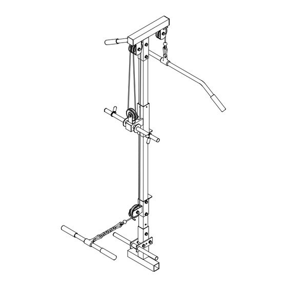
Page 10: Exploded View
EXPLODED VIEW... -
Page 11: Chain,
Product. To obtain warranty service, you must contact a Keys authorized retailer, service technician or Keys Fitness at our phone number located in this manual. Any parts determined to be defective must be returned to Keys to obtain warranty service. You must prepay any shipping charges, export taxes, custom duties and taxes, or any other charges associated with transportation of the parts or Product. - Page 12 Keys Fitness Products, L.P. 4009 Distribution Drive, Suite 250 Garland, Texas 75041 Customer Service: 1-800-683-1236...
Need help?
Do you have a question about the Power System KPS-LATA and is the answer not in the manual?
Questions and answers