Groen AH/1 Operator's Manual
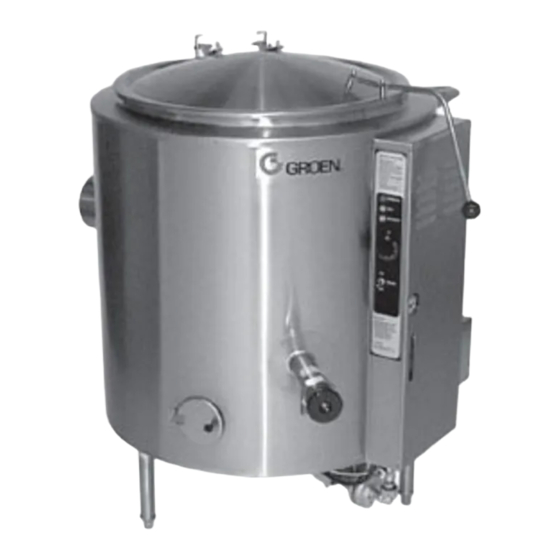
Steam jacketed kettles
Hide thumbs
Also See for AH/1:
- Specifications (1 page) ,
- Brochure (4 pages) ,
- Operator's manual (24 pages)
Advertisement
OPERATOR MANUAL
Model :AH/1,AH/1E
Steam Jacketed Kettles
Self-contained
Stainless steel
Gas heated
Floor mounted
Stationary
THIS MANUAL MUST BE RETAINED FOR FUTURE REFERENCE.
READ, UNDERSTAND AND FOLLOW THE INSTRUCTIONS AND
WARNINGS CONTAINED IN THIS MANUAL.
DO NOT STORE OR USE GASOLINE OR OTHER FLAMMABLE VAPORS
AND LIQUIDS IN THE VICINITY OF THIS.OR ANY OTHER APPLIANCE
POST IN A PROMINENT LOCATION
INSTRUCTIONS TO BE FOLLOWED IN THE EVENT USER SMELLS
GAS. THIS INFORMATION SHALL BE OBTAINED BY CONSULTING
YOUR LOCAL GAS SUPPLIER. AS A MINIMUM, TURN OFF THE GAS
AND CALL YOUR GAS COMPANY AND YOUR AUTHORIZED SERVICE
AGENT. EVACUATE ALL PERSONNEL FROM THE AREA.
WARNING: IMPROPER INSTALLATION, ADJUSTMENT, ALTERATION,
SERVICE OR MAINTENANCE CAN CAUSE PROPERTY DAMAGE,
INJURY OR DEATH. READ THE INSTALLATION, OPERATING AND
MAINTENANCE INSTRUCTIONS THOROUGHLY BEFORE INSTALLING
OR SERVICING THIS EQUIPMENT.
FOR YOUR SAFETY
OM-AH
Advertisement
Table of Contents
Troubleshooting

Related Manuals for Groen AH/1


Summary of Contents for Groen AH/1
- Page 1 OPERATOR MANUAL OM-AH Model :AH/1,AH/1E Steam Jacketed Kettles Self-contained Stainless steel Gas heated Floor mounted Stationary THIS MANUAL MUST BE RETAINED FOR FUTURE REFERENCE. READ, UNDERSTAND AND FOLLOW THE INSTRUCTIONS AND WARNINGS CONTAINED IN THIS MANUAL. FOR YOUR SAFETY DO NOT STORE OR USE GASOLINE OR OTHER FLAMMABLE VAPORS AND LIQUIDS IN THE VICINITY OF THIS.OR ANY OTHER APPLIANCE...
-
Page 2: Table Of Contents
Table of Contents OPERATOR WARNINGS EQUIPMENT DESCRIPTION 2, 3,4 INSPECTION & PACKING INSTALLATION & START-UP OPERATION CLEANING PREVENTIVE MAINTENANCE 10, 11 TROUBLESHOOTING (OPERATOR SEQUENCE OF OPERATION SERVICE TROUBLESHOOTING 14, 15, 16, 17 PARTS LISTS 18, 19,20, 21, 22, 23, 24,25 DIAGRAMS &... - Page 3 SUPPLY AND CLOSE THE MAIN GAS COCK. ALLOW FIVE MINUTES FOR UNBURNED GAS TO VENT. CAUTION: USE OF ANY REPLACEMENT PARTS OTHER THAN THOSE SUPPLIED BY GROEN OR THEIR AUTHORIZED DISTRIBUTOR CAN CAUSE INJURY TO THE OPERATOR AND DAMAGE TO THE EQUIPMENT AND WILL VOID ALL WARRANTIES.
-
Page 4: Equipment Description
A closed steam jacket covers the lower 2/3 of the kettle. Heat from gas flames boils water in the jacket to produce steam under pressure. To ignite the flames, Model AH/1 has a continuously burning pilot flame, called the standing pilot, and Model AH/1E has electronic spark ignition. - Page 5 Model AH/1...
- Page 6 Equipment Description (cont'd) KETTLE CHARACTERISTICS Firing rate, BTU/hour Natural Propane Model Ignition AH/1-20 Pilot 85,000 85,000 AH/1-40 Pilot 100,000 85,000 AH/1-60 Pilot 145,000 145,000 AH/1-80 Pilot 145,000 145,000 AH/1-100 Pilot . 145,000 145,000 AH/1E-20 Spark 85,000 85,000 AH/1E-40 Spark 100,000...
-
Page 7: Installation & Start-Up
(drawing D-6038). Do not change the diverter in any way. Any mechanical, electrical, or gas type change must be aDDroved bv the Groen Food Service Enaineerina Deoartment. WARNING: DO NOT ATTACH THE UNIT TO A TYPE "B" VENT. FAILURE COULD RESULT IN FIRE OR PROPERTY DAMAGE. - Page 8 5. To turn off the unit, follow "To Turn Off Kettle" instructions in the "Operation" section. If the kettle functions as described above, it is ready for use. If it does not, contact your area Groen representative.
-
Page 9: Operation
(1) Press the ON/OFF switch to "ON". (2) Turn the thermostat dial to the desired setting. h. If you must light the pilot burner in a Model AH/1, look through the access hole in the cover of the control housing to see which kind of pilot system is in your unit. - Page 10 Operation (cont'd) Light the pilot burner by the procedure that applies to your unit. With Basotrol standing pilot ignition system: Locate the red reset button on the automatic gas valve inside the control housing. You can reach the button through the hole below the pressure gauge. Hold a flame to the pilot burner and press down the reset button to start the flow of gas.
-
Page 11: Cleaning
Cleaning Suggested Tools Detergent and sanitizer, or a combination cleaning-sanitizing agent like Micro-Quat from ECOLAB. Kettle brushes. Bottle brush for cleaning the draw-off (product faucet). Precautions Before any cleaning operation: Turn off the main burner by turning the thermostat dial to "OFF". Cut off electric power to the unit at the circuit breaker or fuse box. -
Page 12: Preventive Maintenance
Preventive Maintenance This section describes actions the operator must take to keep warranty coverage of the unit and to keep the unit working safely and efficiently. 1. Jacket Vacuum Every day, while the kettle is cold, read the pressure/vacuum gauge. A positive pressure reading or a vacuum reading between zero and 20 on the pressure/vacuum gauge indicates an excess of air in the jacket. - Page 13 Allow the kettle to cool completely. Remove the pipe plug from the jacket fill assembly, then open the globe valve and pour in the distilled or treated water. Hold the safety valve open while you pour, to let air escape from the jacket. Continue adding water until the water level rises to a point between the marks on the gauge glass.
-
Page 14: Troubleshooting
If the actions suggested in this list do not solve the problem, call your Groen Certified Service Agency. To get the phone number of the nearest agency, call the your Area Groen representative or the Groen Parts and Service Department. -
Page 15: Sequence Of Operation
Gas flows to the main burner and is ignited by the pilot flame. B. Model AH/1 E with Electronic Spark Ignition When the operator presses the toggle switch to "ON", electric power at 120V is supplied to the thermostat. -
Page 16: Service Troubleshooting
Service Troubleshooting The Groen kettle is designed to operate smoothly and efficiently if properly maintained. However, the following is a list of checks to make in the event of a problem. Wiring diagrams are furnished inside the service panel. If an item on the list is followed by an asterisk (*), the work should be done by a factory authorized service representative. - Page 17 Models with Standing Pilot Ignition (Refer to the electrical schematic) SYMPTOM WHAT TO CHECK Pilot burner will not light. Lighting procedure. See the "Operation" section of this manual. Pilot tubing and orifice for clogging.* That the pilot gas supply line is purged of air.* Gas pressure at the automatic valve.* Pilot flame goes out when reset button is released.
- Page 18 Service Troubleshooting (cont’d) The Groen kettle is designed to operate smoothly and efficiently if properly maintained. However, the following is a list of checks to make in the event of a problem. Wiring diagrams are furnished inside the service panel. If an item on the list is followed by an asterisk (*), the work should be done by a factory authorized service representative.
- Page 19 SYMPTOM WHAT TO CHECK Pilot lights, but main burner will not come on, and Sensor cable, to make sure of secure attachments the spark stays on. to the sensor and to terminal "4" on the G60* That the cable is not grounded out. If it is, correct the ground.* Cable for continuity and condition of insulation.* Sensor ceramic for cracks.*...
- Page 20 C-7288-2 AH/I — 20, 30, & 40 Gallon Models...
- Page 21 Parts Lists To order parts, contact your Groen Certified Service Agency. Supply the model designation, part description, part number, quantity, and, where applicable, voltage and phase or type of gas. A. AH/1 -20, 30, and 40 Gallon Models ITEM PART...
- Page 22 AH/I —60,80, & 100 Gallon Models...
-
Page 23: Parts Lists
Parts Lists (cont'd) To order parts, contact your Groen Certified Service Agency. Supply the model designation, part description, part number, quantity and, where applicable, voltage and phase or type of gas. B. AH/1-60, 80, and 100 Gallon Models ITEM PART... - Page 24 AH/IE — 20, 30. & 40 Gallon Models...
- Page 25 Parts Lists (cont'd) To order parts, contact your Groen Certified Service Agency. Supply the model designation, part description, part number, quantity, and, where applicable, voltage and phase or type of gas. C. AH/1 E--20, 30, and 40 Gallon Models ITEM...
- Page 26 AH/1E —60, 80, & 100 Gallon Models...
-
Page 27: Parts List
Parts List To order parts, contact your Groen Certified Service Agency. Supply the model designation, part description, part number, quantity, and, where applicable, voltage and phase or type of gas. D. AH/1 E-60, 80, and 100 Gallon Models ITEM PART... - Page 29 AH/1 E Electrical Spark Ignition — Natural Gas For units built between March, 1984 and June, 1989 AH/1 E Electrical Spark Ignition — Propane Gas For units built between March, 1984 and June, 1989...
- Page 30 Wiring Diagrams (cont'd) AH/IE Electrical Spark Ignition For units built between June, 1989 and June 1996...
Need help?
Do you have a question about the AH/1 and is the answer not in the manual?
Questions and answers