Table of Contents
Advertisement
This publication, including photographs, illustrations and software,
is under the protection of international copyright laws, with all
rights reserved. Neither this manual, nor any of the material
contained herein, may be reproduced without the express written
consent of the manufacturer.
The information in this document is subject to change without
notice. The manufacturer makes no representations or warranties
with respect to the contents hereof and specifically disclaims any
implied warranties of merchantability or fitness for any particular
purpose. Further, the manufacturer reserves the right to revise this
publication and to make changes from time to time in the content
hereof without obligation of the manufacturer to notify any person
of such revision or changes.
Trademarks
IBM, VGA, and PS/2 are registered trademarks of International
Business Machines.
Intel, Pentium II/III, Pentium 4, Celeron and MMX are registered
trademarks of Intel Corporation.
Microsoft, MS-DOS and Windows 98/ME/NT/2000/XP are
registered trademarks of Microsoft Corporation.
PC-cillin is a trademark of Trend Micro Inc.
AMI is a trademark of American Megatrends Inc.
It has been acknowledged that other brands or product names in
this manual are trademarks or the properties of their respective
owners.
Motherboard User's Guide
Copyright © 2004
All Rights Reserved
M909G Series, V5.0
I845/August 2004
i
Advertisement
Table of Contents

Related Manuals for PC Chips M909G Series


Summary of Contents for PC Chips M909G Series
- Page 1 AMI is a trademark of American Megatrends Inc. It has been acknowledged that other brands or product names in this manual are trademarks or the properties of their respective owners. Copyright © 2004 All Rights Reserved M909G Series, V5.0 I845/August 2004...
-
Page 2: Table Of Contents
Motherboard User’s Guide Table of Contents Trademark ................... i Static Electricity Precautions ............iii Pre-Installation Inspection ..............iii Features and Checklist Translation ............ v Chapter 1: Introduction ............1 Key Features ..................2 Package Contents ................5 Chapter 2: Motherboard Installation ........6 Motherboard Components .............. -
Page 3: Static Electricity Precautions
Motherboard User’s Guide Static Electricity Precautions Static electricity could damage components on this motherboard. Take the following precautions while unpacking this motherboard and installing it in a system. 1. Don’t take this mainboard and components out of their original static-proof package until you are ready to install them. - Page 4 Motherboard User’s Guide Notice: Owing to Microsoft’s certifying schedule is various to every supplier, we might have some drivers not certified yet by Microsoft. Therefore, it might happen under Windows XP that a dialogue box (shown as below) pop out warning you this software has not passed Windows Logo testing to verify its compatibility with Windows XP.
- Page 5 Motherboard User’s Guide Traduction des Caractéristiques & Liste de contrôle Liste de contrôle Le coffret de votre carte mère contient les éléments suivants : La carte mère • Le Manuel utilisateur • Un câble plat pour lecteur de disquette (optionnel) •...
- Page 6 Motherboard User’s Guide Ports E/S Internes La carte mère possède un jeu complet de ports d’E/S et de connecteurs: • Deux ports PS/2 pour souris et clavier • Un port série • Un port VGA • Un port parallèle • Six ports USB (quatre ports fond de panier, prises USB internes offrant deux ports supplémentaires)—...
- Page 7 Motherboard User’s Guide Funktionen & Checkliste Checkliste Die Verpackung Ihres Motherboards enthält folgende Teile: Motherboard • Handbuch • Bandkabel für Floppylaufwerke (optional) • Bandkabel für IDE-Laufwerke • Software -CD • Ausstattung Unterstütz Socket-478-Prozessoren Unterstützung für Intel Pentium 4-CPUs mit/ohne “Hyper-Threading”-Tech- •...
- Page 8 Motherboard User’s Guide Onboard I/O-Steckplätze Das Motherboard verfügt über einen kompletten Satz von I/O-Steckplätze und Anschlüssen: • Zwei PS/2-Steckplätze für Maus und Tastatur yboard • Ein serieller Steckplatz • Ein VGA-Steckplatz • Ein paralleler Steckplatz • Sechs USB Ports (vier Ports an der Rückseite, onboard USB-Köpfe, welche zwei weitere Ports bieten)-USB2.0 •...
- Page 9 Motherboard User’s Guide Traduzione Funzioni e Lista Lista L’imballo della scheda madre é composto da: La scheda madre • Il manuale • Una piattina per il collegamento dei drive (opzionale) • Una piattina IDE • Il CD con il Software di supporto •...
- Page 10 Motherboard User’s Guide Onboard I/O Porta La scheda madre è dotata da una serie completa di porte e connettori I/O: • Due porte PS/2 per tastiera e mouse • Una porta seriale • Una porta VGA • Una porta parallela •...
- Page 11 Motherboard User’s Guide Traducción de Características & Lista LISTA DE VERIFICACIÓN El paquete de su placa principal contiene los sigtes. ítems: La placa principal • El Manual del Usuario • Un cable cinta para el lector de disquete (optativo) • Un cable cinta para el lector IDE •...
- Page 12 Motherboard User’s Guide Puertos I/O Abordos La placa principal tiene un juego completo de puertos I/O y conectores: • Dos puertos PS/2 para ratón y teclado • Un puerto serial • Un puerto VGA • Un puerto paralelo • Seis puertos USB (cuatro puertos del panel trasero, los cabezales USB abordo provee dos puertos extras)-USB2.0 •...
- Page 13 Motherboard User’s Guide Tradução da Lista & Características Lista de verificação A embalagem da sua placa principal contém os seguintes itens: • A placa principal • O Manual do Utilizador • Um cabo para a unidade de disquetes (opcional) • Um cabo para a unidade IDE •...
- Page 14 Motherboard User’s Guide Portas I/O na placa A placa principal possui um conjunto completo de portas e conectores I/O: • Duas portas PS/2 para o rato e teclado • Uma porta série • Uma porta VGA • Uma porta paralela •...
- Page 15 Motherboard User’s Guide 功能和检查单翻译 检查单 您的主板包装含有以下项目: 主板 • 用户手册 • 一根磁盘驱动器扁平电缆(可选) • 一根 IDE 驱动器扁平电缆 • 软件支持 CD • 功能 支持 Socket-478 处理器 支持带有/不带有多线程技术的 Intel Pentium 4 系列 CPU • 支持 533/400 MHz 前端总线 • 芯片组 Intel 845GV/GL 芯片组包含 Intel 82845 存储控制器 Hub (ICH4)和 Intel 82801DB I/O 控制器...
- Page 16 Motherboard User’s Guide 集成 I/O 端口 此主板具有完整的 I/O 端口和插孔: • 2 个用于连接鼠标和键盘的 PS/2 端口 • 1 个串口 • 1 个 VGA 端口 • 1 个并口 • 6 个 USB 端口(主板后面板带 4 个接口,板上 USB 接口提供其它 2 个端 口)— USB2.0 • 麦克风、线入和线出声音插孔 快速以太网...
-
Page 17: Chapter 1 Introduction
Chapter 1: Introduction Chapter 1 Introduction This motherboard has a Socket-478 supporting Intel Pentium 4/ Prescott with Hyper-Threading Technology processors with Front-Side Bus (FSB) speeds up to 533/400 MHz. Hyper- Threading Technology, designed to take advantage of the multitasking features in Windows XP, gives you the power to do more things at once. -
Page 18: Key Features
Motherboard User’s Guide Note: You must initiate the HT CPU function through BIOS setup. It is strongly recommended you refer to Page 48 for related details. Key Features The key features of this motherboard include: Socket-478 Processor Supports Intel Pentium 4 series CPU with/without Hyper-Threading Technology Supports up to 533/400 MHz Front-Side Bus Chipset... - Page 19 Chapter 1: Introduction Support DDR up to 333MHz (845GV) or DDR266MHz (845GL) memory bus Maximum installed memory is 2GB AC’97 Codec Compliant with AC’97 2.3 specification Full-duplex Codec with independent and variable sampling rate Earphone Buffer Built-In, SNR up to 90db 6Ch DAC, support 6-channel speak-out Advanced power management support Expansion Options...
- Page 20 Motherboard User’s Guide Compliant to PC99/PC2001 standard Supports a 32-bit general-purpose timer with the external PCI clock as clock source, to generate timer-interrupt Supports Full Duplex Flow Control (IEEE 802.3x) USB 2.0 Includes three UHCI host controllers that support six external ports New: Includes one EHCI high-speed USB 2.0 Host Con- troller that supports all six ports...
-
Page 21: Package Contents
Chapter 1: Introduction Package Contents Your motherboard package contains the following items: The motherboard The User’s Guide One diskette drive ribbon cable (optional) One IDE drive ribbon cable Software support CD Optional Accessories You can purchase the following optional accessories for this motherboard. -
Page 22: Chapter 2 Motherboard Installation
Motherboard User’s Guide Chapter 2 Motherboard Installation To install this motherboard in a system, please follow these instructions in this chapter: • Identify the motherboard components • Install a CPU • Install one or more system memory modules • Make sure all jumpers and switches are set correctly •... -
Page 23: Motherboard Components
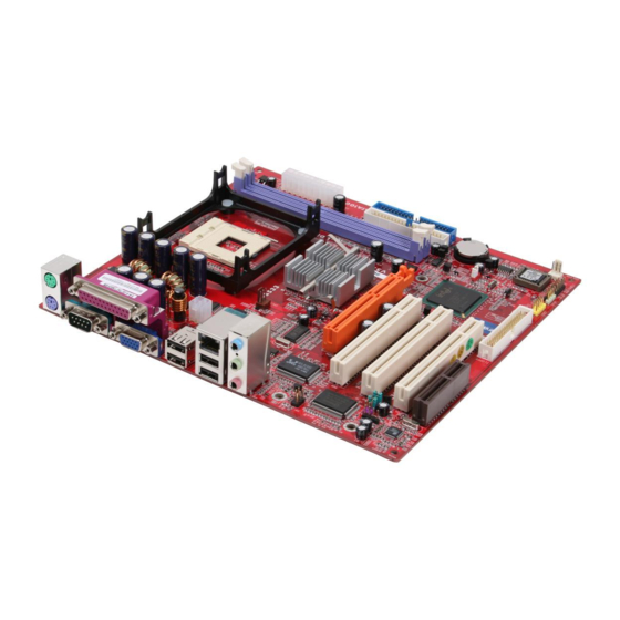
Chapter 2: Motherboard Installation Motherboard Components Socket-478 DDR1/2 ATX1 PORTS CPU FAN IDE2/1 AGP1 SIR1 AUDIO2 PLED1 CHS FAN CN R1 PCI1-3 FLOPPY USB3 SPKR1 PANEL1 LABEL COMPONENTS DDR1-2 Two 184-pin DDR SDRAM sockets IDE1/2 Primary/Secondary IDE connectors ATX1 Standard 4-Pin ATX Power connector Standard 20-Pin ATX Power connector USB3 Front Panel USB header... -
Page 24: I/O Ports
Motherboard User’s Guide LABEL COMPONENTS SIR1 Infrared Port header PCI 1-3 32-bit PCI slots AUDIO2 Front Panel Audio header CPUFAN CPU Fan connector CNR1 Communications Networking Riser slot AGP1 AGPro slot *See page 21 for details I/O Ports The illustration below shows a side view of the built-in I/O ports on the motherboard. -
Page 25: Installing The Processor
Chapter 2: Motherboard Installation Installing the Processor This motherboard has a Socket 478 processor socket. When choosing a processor, consider the performance requirements of the system. Performance is based on the processor design, the clock speed and system bus frequency of the processor, and the quantity of internal cache memory and external cache memory. -
Page 26: Installing Memory Modules
Motherboard User’s Guide Installing Memory Modules This motherboard accommodates two 184-pin 2.5V unbuffered Double Data Rate SDRAM (DDR SDRAM) Dual Inline Memory Module (DIMM) sockets, and supports up to 2.0 GB of 333(845GV)/266/200 MHz DDR SDRAM. DDR SDRAM is a type of SDRAM that supports data transfers on both edges of each clock cycle (the rising and falling edges), effectively doubling the memory chip’s data throughput. - Page 27 Chapter 2: Motherboard Installation Memory Module Installation Procedure These modules can be installed with up to 2 GB system memory. Refer to the following to install the memory module. Push down the latches on both sides of the DIMM socket. Align the memory module with the socket.
-
Page 28: Jumper Settings
Motherboard User’s Guide Jumper Settings Connecting two pins with a jumper cap is SHORT; removing a jumper cap from these pins, OPEN. JP2: Clear CMOS Jumper Use this jumper to clear the contents of the CMOS memory. You may need to clear the CMOS memory if the settings in the Setup Utility are incorrect and prevent your motherboard from operating. -
Page 29: Install The Motherboard
Chapter 2: Motherboard Installation Install the Motherboard Install the motherboard in a system chassis (case). The board is a Micro-ATX size motherboard. You can install this motherboard in an ATX case. Make sure your case has an I/O cover plate matching the ports on this motherboard. -
Page 30: Connecting Optional Devices
Motherboard User’s Guide Please refer to the following list of the PANEL1 pin assignments. Signal Signal 1 HD_LED_P(+) 2 FP PWR/SLP(+) 3 HD_LED_N(-) 4 FP PWR/SLP(-) 5 RESET_SW_N(-) 6 POWER_SW_P(+) 7 RESET_SW_P(+) 8 POWER_SW_N(-) RSVD_DNU 10 KEY Connecting Optional Devices Refer to the following for information on connecting the motherboard’s optional devices: SIR1... - Page 31 Chapter 2: Motherboard Installation AUDIO2: Front Panel Audio Header This header allows the user to install auxiliary front-oriented microphone and line-out ports for easier access. Signal Signal AUD_MIC AUD_GND AUD_MIC_BIAS AUD_VCC AUD_FPOUT_R AUD_RET_R HP_ON AUD_FPOUT_L 10 AUD_RET_L USB3: Front Panel USB Header The motherboard has USB ports installed on the rear edge I/O port array.
- Page 32 Motherboard User’s Guide PLED1: Power-On Indicator Header If there is another power-on indicator LED installed in the system chassis, connect the LED to the PLED1 header. Signal GROUND POWER SIR1: Infrared Header The infrared port allows the wireless exchange of information between your computer and similarly equipped devices such as printers, laptops, Personal Digital Assistants (PDAs), and other computers.
-
Page 33: Install Other Devices
Chapter 2: Motherboard Installation Install Other Devices Install and connect any other devices in the system following the steps below. IDE2 IDE1 FLOPPY Floppy Disk Drive The motherboard ships with a floppy disk drive cable that can support one or two drives. Drives can be 3.5" or 5.25" wide, with capacities of 360K, 720K, 1.2MB, 1.44MB, or 2.88MB. - Page 34 Motherboard User’s Guide IDE Devices IDE devices include hard disk drives, high-density diskette drives, and CD-ROM or DVD-ROM drives, among others. The motherboard ships with an IDE cable that can support one or two IDE devices. If you connect two devices to a single cable, you must configure one of the drives as Master and one of the drives as Slave.
- Page 35 Chapter 2: Motherboard Installation Analog Audio Input Header If you have installed a CD-ROM drive or DVD-ROM drive, you can connect the drive audio cable to the onboard sound system. When you first start up your system, the BIOS should automati- cally detect your CD-ROM/DVD drive.
-
Page 36: Expansion Slots
Motherboard User’s Guide Expansion Slots This motherboard has one AGPro, one CNR and three 32-bit PCI slots. AGP1 PCI1 PCI2 PCI3 CNR1 Follow the steps below to install a CNR/PCI expansion card. Locate the CNR or PCI slots on the motherboard. Remove the slot cover for this slot from the system chassis. - Page 37 Chapter 2: Motherboard Installation Note: If the AGP card is already installed, the computer won’t auto setup the onbaord VGA driver. VGA Card Support List for AGPro Slot: VENDER AGP 4X/8X CHIPSET MANUFACTURE ATI Radeon 8500 ATI RADEON 8500 DDR ATI Radeon 9000 PRO Gigabyte GV-R9000 PRO ATI Radeon 9200...
- Page 38 Motherboard User’s Guide Once the AGP card is completely installed under Windows 2000 or Windows XP, the sign like this “? Video Controller” will pop up below the “Device Manager” as the following picture shows. It is normal to see the sign as the onboard VGA card is “Dis- abled”.
-
Page 39: Dual Monitor
Chapter 2: Motherboard Installation PCI Slot You can install the 32-bit PCI interface expansion cards in the slots. CNR Slot This slot is used to insert CNR (Communications and Networking Riser) cards including LAN, Modem, and Audio functions. Dual Monitor In order to enable “Dual Monitor”... - Page 40 Motherboard User’s Guide Step 2: Install the Add-on AGP Card Shut down the system Install the add-on AGP card in the AGPro slot Turn on the computer Note: When you turn on the system, windows might report Found New Hardware Wizard, “Video Controller(VGA Compatible)”...
- Page 41 Chapter 2: Motherboard Installation Step 5: Right click the desktop. Select “Properties” See the picture below: Step 6: Select “Display Properties” Click “Settings” Then the parameters of the two monitors can be adjusted.
- Page 42 Motherboard User’s Guide Dual Monitor Installation (For Windows 2000) If the onboard VGA is first installed, and you would like to use the add-on AGP card. Please follow the installation steps 1-6. Users may go to step 4 directly if the add-on AGP card is installed first and then turned on the onboard VGA devices for “secondary display”.
- Page 43 Chapter 2: Motherboard Installation Step 4: Install the Onboard VGA Driver Install the onboard VGA driver from our support CD to utilize Dual Monitor Function. Here is the Driver Path: CD-ROM:\VGA\Intel845g\WIN2K&XP\Graphics\Setup.exe Restart the computer Note: If the add-on AGP card driver and onboard VGA drivers are installed, the dual-monitor display will be enabled.
- Page 44 Motherboard User’s Guide MEMO...
-
Page 45: Chapter 3 Bios Setup Utility
Chapter 3: BIOS Setup Utility Chapter 3 BIOS Setup Utility Introduction The BIOS Setup Utility records settings and information of your computer, such as date and time, the type of hardware installed, and various configuration settings. Your computer applies the information to initialize all the components when booting up and basic functions of coordination between system components. -
Page 46: Running The Setup Utility
Motherboard User’s Guide Running the Setup Utility Every time you start your computer, a message appears on the screen before the operating system loading that prompts you to “Hit <DEL>if you want to run SETUP”. Whenever you see this message, press the Delete key, and the Main menu page of the Setup Utility appears on your monitor. -
Page 47: Standard Cmos Setup Page
Chapter 3: BIOS Setup Utility Standard CMOS Setup Page This page displays a table of items defining basic information about your system. AMIBIOS SETUP – STANDARD CMOS SETUP (C) 2000 American Megatrends, Inc. All Rights Reserved Date (mm/dd/yyyy) : Tue Jun 08, 2004 Time (hh/mm/ss) 12:41:42 32Bit... -
Page 48: Advanced Setup Page
Motherboard User’s Guide Advanced Setup Page This page sets up more advanced information about your system. Handle this page with caution. Any changes can affect the operation of your computer. AMIBIOS SETUP – ADVANCED SETUP (C) 2000 American Megatrends, Inc. All Rights Reserved Memory Voltage Control 2.6V Quick Boot... -
Page 49: Features Setup Page
Chapter 3: BIOS Setup Utility S.M.A.R.T. for Hard Disks Enable this item if any IDE hard disks support the S.M.A.R.T. (Self-Monitoring, Analysis and Reporting Technology) feature. Floppy Drive Swap If you have two diskette drives installed and you enable this item, drive A becomes drive B and drive B becomes drive A. - Page 50 Motherboard User’s Guide SDRAM CAS # Latency This item determins the operation of SDRAM memory CAS (column address strobe.) It is recommended that you leave this item at the default value. The 2T setting requires faster memory that specifically supports this mode. SDRAM RAS# Precharge Select the number of CPU clocks allocated for the Row Address Strobe (RAS#) signal to accumulate its charge before the...
-
Page 51: Power Management Setup Page
Chapter 3: BIOS Setup Utility Memory Voltage Control Use this item to adjust the voltage of the memory. Power Management Setup Page This page sets some parameters for system power management operation. AMIBIOS SETUP – POWER MANAGEMEMT SETUP (C) 2000 American Megatrends, Inc. All Rights Reserved ACPI Aware O/S Power Management Enabled... - Page 52 Motherboard User’s Guide Resume On RTC Alarm / Date / Hour / Minute / Second The system can be turned off with a software command. If you enable this item, the system can automatically resume at a fixed time based on the system’s RTC (realtime clock). Use the items below this one to set the date and time of the wake-up alarm.
-
Page 53: Pci/Plug And Play Setup Page
Chapter 3: BIOS Setup Utility PCI / Plug and Play Setup Page This page sets up some parameters for devices installed on the PCI bus and those utilizing the system plug and play capability. AMIBIOS SETUP – PCI / PLUG AND PLAY SETUP (C) 2000 American Megatrends, Inc. -
Page 54: Load Optimal Settings
Motherboard User’s Guide Load Optimal Settings If you select this item and press Enter a dialog box appears. If you press Y, and then Enter, the Setup Utility loads a set of fail- safe default values. These default values are not very demanding and they should allow your system to function with most kinds of hardware and memory chips. -
Page 55: Features Setup Page
Chapter 3: BIOS Setup Utility Features Setup Page This page sets up some parameters for peripheral devices connected to the system. AMIBIOS SETUP – FEATURES SETUP (C) 2000 American Megatrends, Inc. All Rights Reserved OnBoard FDC Enabled 3F8/COM1 OnBoard Serial Port A OnBoard IR Port Disabled OnBoard Parallel Port... - Page 56 Motherboard User’s Guide Parallel Port Mode This item sets the parallel port mode. You can select Normal (Standard Parallel Port), Bi-Dir(Bi-Directional), EPP (Enhanced Parallel Port), or ECP(Extended Capabilities Port). EPP Version This item is for setting the EPP version. You can select version 1.7 or version 1.9.
-
Page 57: Cpu Pnp Setup Page
Chapter 3: BIOS Setup Utility CPU PnP Setup Page This page helps you manually configure the motherboard for the CPU. The system will automatically detect the type of installed CPU and make the appropriate adjustments to the items on this page. AMIBIOS SETUP –... -
Page 58: Hardware Monitor Page
Motherboard User’s Guide Hardware Monitor Page This page sets up some parameters for the hardware monitoring function of this motherboard. AMIBIOS SETUP –HARDWARE MONITOR (C) 2000 American Megatrends, Inc. All Rights Reserved *** System Hardware *** Vcore 1.536 V 3.232 V Vcc3.3V 5.085 V +12V... -
Page 59: Change Password And Exit
Chapter 3: BIOS Setup Utility Change Password If you highlight this item and press Enter, a dialog box appears that you can enter a Supervisor password. You can enter no more than six letters or numbers. Press Enter after you have typed in the password. -
Page 60: Chapter 4 Software & Applications
Motherboard User’s Guide Chapter 4 Software & Applications Introduction This chapter describes the contents of the support CD-ROM that comes with the motherboard package. The support CD-ROM contains all useful software, necessary drivers and utility programs to properly run our products. More program information is available in a README file, located in the same directory as the software. -
Page 61: Installing Support Software
Chapter 4: Software & Applications Installing Support Software Insert the support CD-ROM disc in the CD-ROM drive. When you insert the CD-ROM disc in the system CD- ROM drive, the CD automatically displays an Auto Setup screen. The screen displays three buttons of Setup, Browse CD and Exit on the right side, and three others Setup, Application and ReadMe at the bottom. - Page 62 Motherboard User’s Guide Auto-Installing under Windows 98/ME/2000/XP If you are under Windows 98/ME/2000/XP, please click the Setup button to run the software auto-installing program while the Auto Setup screen pops out after inserting the support CD-ROM: The installation program loads and displays the following screen.
-
Page 63: Bundled Software Installation
Chapter 4: Software & Applications Installing under Windows NT or Manual Installation If you are under Windows NT, the auto-installing program doesn’t work out; or you have to do the manual installation, please follow this procedure while the Auto Setup screen pops out after insert- ing the support CD-ROM: Click the ReadMe to bring up a screen, and then click the Install Path at the bottom of the screen. -
Page 64: Hyper-Threading Cpu
Motherboard User’s Guide Hyper-Threading CPU You must update BIOS to initiate BIOS Hyper-Threading Func- tion and use HT CPU function under WinXP Operating System; if not, please disable this option. • When BIOS detects the HT CPU, it shows the “Hyper- Threading Function (default Disabled)”...
Need help?
Do you have a question about the M909G Series and is the answer not in the manual?
Questions and answers