Table of Contents
Advertisement
This publication, including all photographs, illustrations and
software, is protected under international copyright laws, with all
rights reserved. Neither this manual, nor any of the material
contained herein, may be reproduced without the express written
consent of the manufacturer.
The information in this document is subject to change without
notice. The manufacturer makes no representations or warranties
with respect to the contents hereof and specifically disclaims any
implied warranties of merchantability or fitness for any particular
purpose. Further, the manufacturer reserves the right to revise this
publication and to make changes from time to time in the content
hereof without obligation of the manufacturer to notify any person
of such revision or changes.
Trademarks
IBM, VGA, and PS/2 are registered trademarks of International
Business Machines.
AMD, Athlon XP, Sempron, Athlon and Duron are registered
trademarks of Advanced Micro Devices Inc.
Microsoft, MS-DOS and Windows 98/ME/NT/2000/XP are
registered trademarks of Microsoft Corporation.
PC-cillin is a registered trademark of Trend Micro Inc.
AMI is a registered trademark of American Megatrends Inc.
Other names used in this publication may be trademarks and are
acknowledged.
Copyright © 2004
All Rights Reserved
M825G Series, V9.2B
KM266Pro/July 2004
i
Advertisement
Table of Contents

Related Manuals for PC Chips M825G Series


Summary of Contents for PC Chips M825G Series
- Page 1 PC-cillin is a registered trademark of Trend Micro Inc. AMI is a registered trademark of American Megatrends Inc. Other names used in this publication may be trademarks and are acknowledged. Copyright © 2004 All Rights Reserved M825G Series, V9.2B KM266Pro/July 2004...
-
Page 2: Table Of Contents
Table of Contents Trademark ..................I Static Electricity Precautions..........III Pre-Installation Inspection .............III Features & Checklist Translations..........V Chapter 1: Introduction ..............1 Key Features ................2 Package Contents..............5 Chapter 2: Motherboard Installation ..........6 Motherboard Components ............7 I/O Ports...................7 Installing The Processor ............8 Installing The Memory Modules ..........9 Jumper Settings..............10 Installing The Motherboard ...........11 Connecting Optional Devices ..........12... -
Page 3: Static Electricity Precautions
Static Electricity Precautions Components on this motherboard can be damaged by static electricity. Take the following precautions when unpacking the motherboard and installing it in a system. 1. Keep the motherboard and other components in their original static-proof packaging until you are ready to install them. 2. - Page 4 Notice: 1. Owing to Microsoft’s certifying schedule is various to every supplier, we might have some drivers not certified yet by Microsoft. Therefore, it might happen under Windows XP that a dialogue box (shown as below) pop out warning you this software has not passed Windows Logo testing to verify its compatibility with Windows XP.
-
Page 5: Features & Checklist Translations
Features & Checklist Translations Liste de contrôle Le coffret de votre carte mère contient les éléments suivants : La carte mère Le Manuel utilisateur Un câble plat pour lecteur de disquette (optionnel) Une câble plat pour lecteur IDE CD de support de logiciels Caractéristiques Prise en charge du Processeur Socket-462 Processeur... - Page 6 (Accès Direct à la Mémoire) • Supporte maîtrise de bus UltraDMA IDE avec vitesse de transfert de 133/100/66/33 Mo/sec • Prend en charge les tailles de Tampons de Trame de 16/32/64 Mo • Moteur graphique 3D/2D 128 bits • Performance AGP 8X Interne •...
- Page 7 Certaines spécifications matérielles et éléments de logiciels peuvent être modifiés sans avertissement .
- Page 8 Checkliste Die Verpackung Ihres Motherboards enthält folgende Teile: Motherboard Handbuch Bandkabel für Floppylaufwerke (optional) Bandkabel für IDE-Laufwerke Software-CD Ausstattung Unterstütz Socket-462-Prozessoren Prozessor • Unterstützung für AMD Athlon XP/Sempron/Athlon/Duron prozessors • Unterstützung von bis zu 333/266/200 MHz Front-Side Bus Dieser Chipsatz besteht aus einer VIA KM266Pro Northbridge und einer Chipsatz VIA 8235 Southbridge.
- Page 9 • Unterstützung für IDE UltraDMA-Busmastering mit Transferraten von 133/100/66/33 MB/Sek • Unterstützt Rahmenpuffergrössen von 16/32/64 MB • 128-Bit3D/2D-Grafikmotor • Interne 8X AGP-Leistung • Nach den Richtlinien von AGP Rev. 3.0 • 6-Kanäle und gemäß Spezifikationen von Intel AC’97 (REV. 2.3) , AC’97 Codec ...
- Page 10 Lista L’imballo della scheda madre é composto da: La scheda madre Il manuale Una piattina per il collegamento dei drive (opzionale) Una piattina IDE Il CD con il Software di supporto Caratteristiche Dotata di Socket 462 per Processori Processor • Supporta CPU AMD Athlon XP/Sempron/Athlon/Duron •...
- Page 11 • Due connettori IDE Onboard IDE • Supporto della modalità PIO (Programmable Input/Output) e DMA (Direct Memory Access) • Supporto per le modalità Bus Mastering e UltraDMA 133/100/66/33 MB/sec • Supporta Frame Buffer 16/32/64 MB • Motore grafico 128-bit 3D/2D •...
- Page 12 LiSTA DE VERIFICACIÓN El paquete de su placa principal contiene los sigtes. ítems: La placa principal El Manual del Usuario Un cable cinta para el lector de disquete (optativo) Un cable cinta para el lector IDE CD de Software de soporte Características Soporte de Procesador Socket-462 Procesador...
- Page 13 de 133/100/66/33 MB/sec • Soporta tamaños de Buffers de Cuadro 16/32/64 MB • Motor de gráficas 128-bit 3D/2D • Rendimiento AGP 8X interno • Conformidad AGP Rev. 3.0 • 6-canales y conforme con la Espec. Intel AC’97 (REV. 2.3), satisface AC’97 Codec ...
- Page 14 Lista de verificação A embalagem da sua placa principal contém os seguintes itens: A placa principal O Manual do Utilizador Um cabo para a unidade de disquetes (opcional) Um cabo para a unidade IDE CD de suporte para o software Características Processador Suporte do Processador Socket-462...
- Page 15 • Suporta IDE UltraDMA bus mastering com razão de transferência de 133/100/66/33 MB/sec • Com suporte para tamanhos de Frame Buffer de 16/32/64 MB • Barra de gráficos 128-bit 3D/2D • Performance interna AGP 8X • Compatível com AGP Rev. 3.0 ...
- Page 16 检查单 您的主板包装含有以下项目: 主板 用户手册 一根磁盘驱动器扁平电缆(可选) 一根 IDE 驱动器扁平电缆 软件支持 CD 功能 支持 Socket-462 处理器 处理器 • 支持 AMD Athlon XP/Sempron/Athlon/Duron CPU • 支持 333/266/200 MHz 前端总线 芯片组包含 VIA KM266Pro 北桥和 VT8235 南桥,它基于一种新型的、可 芯片组 扩展的架构,能提供已经证明的可靠性和高性能。 • 高性能 CPU 接口:支持 Socket-A (Socket-462) AMD Athlon XP/Sempron/ Athlon/Duron 处理器,333/266/200 MHz 主机地址和数据传输速率...
- Page 17 • 6 通道,符合 Intel AC’97 (REV. 2.3) 规格,满足 Microsoft PC2001 要求 AC’97 编解码 • 高级电源管理和节电功能。 器 • 共享环绕输出的立体声线入功能。 • 高质量伪差分模拟 CD 音频输入。 • 支持 S/PDIF 输入/输出:S/PDIF In 支持中断、自锁、抗噪和抗失真功能。 • 增值软件技术。支持大部分 PC 3D 立体声行业标准和卡拉 OK 功能,支 持话筒回声消除、键移动和声音消除功能。 • 2 个用于鼠标和键盘的 PS/2 端口 集成...
-
Page 19: Chapter 1: Introduction
Chapter 1 Introduction This motherboard has a Socket-A support for the AMD Athlon XP/Sempron/Athlon/Duron processors. The Socket-A processor’s front-side bus (FSB) speed is 333/266/200 MHz. This motherboard integrates VIA KM266Pro Northbridge and VT8235 Southbridge chipsets that support one 4X AGP slot for highly graphics display, two 184-pin DIMM sockets for DDR333/266 memory bus, and UltraDMA ATA133/100/66/33 function to provide outstanding high system performance under all... -
Page 20: Key Features
Key Features The key features of this motherboard include: Socket-A Processor Support ♦ Supports AMD Athlon XP/Sempron/Athlon/Duron processors ♦ Supports Front-Side Bus (FSB) 333/266/200 MHz Chipset There are VIA KM266Pro Northbridge and VT8235 Southbridge in this chipset in accordance with an innovative and scalable architecture with proven reliability and performance. - Page 21 ♦ Universal Serial Bus Controller: USB v2.0 and Enhanced Host Controller Interface (EHCI) v1.0 compatible; USB v1.1 and Universal Host Controller Interface (UHCI) v1.1 compatible Memory Support ♦ Two 184-pin DIMM sockets for DDR333/266 memory bus ♦ Maximum installed memory is 2GB Expansion Slots ♦...
- Page 22 Valuable add-on software technology: Support most industry standards of PC 3D sound and unique karaoke function support featured with microphone echo, key shifting, and vocal cancellation. Onboard I/O Ports The motherboard has a full set of I/O ports and connectors: ♦...
-
Page 23: Package Contents
♦ Legacy support for all downstream facing ports Bundled Software ♦ PC-Cillin provides automatic virus protection under Windows 98/ME/NT/2000/XP ♦ Adobe Acrobat Reader is the software to help users read PDF files. Dimensions ♦ Micro ATX form factor (244 x 190 mm) Note: Hardware specifications and software items are subject to change without notification. -
Page 24: Chapter 2: Motherboard Installation
Chapter 2 Motherboard Installation To install this motherboard in a system, please follow these instructions in this chapter: Identify the motherboard components Install a CPU Install one or more system memory modules Make sure all jumpers and switches are set correctly Install this motherboard in a system chassis (case) Connect any extension brackets or cables to connectors/headers on the motherboard... -
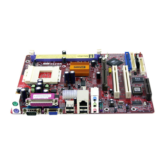
Page 25: Motherboard Components
Motherboard Components This diagram below identifies major components on the motherboard. I/O Ports The illustration below shows a side view of the built-in I/O ports on the motherboard. (optional) -
Page 26: Installing The Processor
Use the upper PS/2 port to connect a PS/2 PS/2 Mouse pointing device. PS/2 Keyboard Use the lower PS/2 port to connect a PS/2 keyboard. LPT1 Use LPT1 to connect printers or other parallel communications devices. COM1 Use the COM port to connect serial devices such as mice or fax/modems. -
Page 27: Installing The Memory Modules
1. Unhook the CPU socket’s locking lever by pulling it away from socket and raising it to the upright position. 2. Match the pin 1 corner of CPU socket to the one of processor, and insert the processor into the socket. Do not use force. -
Page 28: Jumper Settings
Installation Procedure These modules can be installed with up to 2 GB system memory. Refer to the following to install the memory modules. 1. Push the latches on each side of the DIMM socket down. 2. Align the memory module with the socket. The DIMM sockets are keyed with notches and the DIMMs are keyed with cutouts so that they can only be installed correctly. -
Page 29: Installing The Motherboard
Jumper JP2: Clear CMOS Memory This jumper can clear the CMOS memory. You may need to clear the CMOS memory if the settings in the Setup Utility are incorrect that your motherboard can’t operate. To clear the CMOS memory, disconnect all the power cables, and then move the jumper cap into the CLEAR setting for a few seconds. -
Page 30: Connecting Optional Devices
Connect the power connector from the power supply to the ATX1 connector on the motherboard. CPUPW1 is a +12V connector for CPU Vcore power. If there is a cooling fan installed in the system chassis, connect the cable from the cooling fan to the SYSFAN1 fan power connector on the motherboard. - Page 31 AUDIO2: Front Panel Audio Header This header allows the user to install auxiliary front-oriented microphone and line-out ports for easier access. Signal Signal AUD_MIC AUD_GND AUD_MIC_BIAS AUD_VCC AUD_FPOUT_R AUD_RET_R HP_ON AUD_FPOUT_L AUD_RET_L Note: If you want to connect the front panel sound jack, you have to remove jumper caps of Pin(5-6) and Pin(9-10) from the AUDIO2 header.
-
Page 32: Installing Other Devices
SIR1: Infrared Port The infrared port allows the wireless exchange of information between your computer and similarly equipped devices such as printers, laptops, Personal Digital Assistants (PDAs), and other computers. Signal Signal IRTX IRRX 1. Locate the infrared port SIR1 header on the motherboard. 2. - Page 33 Floppy Disk Drive The motherboard ships with a floppy disk drive cable that can support one or two drives. Drives can be 3.5” or 5.25” wide, with capacities of 360K, 720K, 1.2MB, 1.44MB, or 2.88MB. Install your drives and connect power from the system power supply.
- Page 34 Internal Sound Connections If you have installed a CD-ROM drive or DVD-ROM drive, you can connect the drive audio cable to the onboard sound system. When you first start up your system, the BIOS should automatically detect your CD-ROM/DVD drive. If it doesn’t, enter the Setup Utility and configure the CD-ROM/DVD drive that you have installed.
-
Page 35: Expansion Slots
Expansion Slots This motherboard has one AGP, one CNR and two 32-bit PCI slots. AGP1 CNR1 PCI2 PCI1 Follow the steps below to install a PCI/AGP/CNR expansion card. 1. Locate the CNR, AGP or PCI slots on the motherboard. 2. Remove the blanking plate of the slot from the system chassis. 3. -
Page 36: Chapter 3: Bios Setup Utility
Chapter 3 BIOS Setup Utility Introduction The BIOS Setup Utility records settings and information of your computer, such as date and time, the type of hardware installed, and various configuration settings. Your computer applies the information to initialize all the components when booting up and basic functions of coordination between system components. -
Page 37: Running The Setup Utility
Running the Setup Utility Every time you start your computer, a message appears on the screen before the operating system loading that prompts you to “Hit <DEL>if you want to run SETUP”. Whenever you see this message, press the Delete key, and the Main menu page of the Setup Utility appears on your monitor. -
Page 38: Standard Cmos Setup Page
Standard CMOS Setup Page Use this page to set basic information such as the date, the time, the IDE devices, and the diskette drives. If you press the F3 key, the system will automatically detect and configure the hard disks on the IDE channels. -
Page 39: Advanced Setup Page
Advanced Setup Page Use this page to set more advanced information about your system. Take some care with this page. Making changes can affect the operation of your computer. AMIBIOS SETUP – ADVANCED SETUP (C) 2000 American Megatrends, Inc. All Rights Reserved Quick Boot Enabled Boot Device... - Page 40 BootUp Num- This item determines if the Num Lock key is Lock active or inactive at system start-up time. Floppy Drive If you have two diskette drives installed and Swap you enable this item, drive A becomes drive B and drive B becomes drive A. Floppy Drive If you enable this item, your system will check Seek...
-
Page 41: Power Management Setup Page
SDRAM Bank Enable this item to increase SDRAM memory Interleave speed. When enabled, separate memory banks are set for odd and even addresses, and upcoming byte of memory is accessible while refreshing the current byte. Auto Detect When this item is enabled, BIOS will disable DIMM/PCI Clk the clock signal of free DIMM/PCI slots. - Page 42 Suspend Time Out This item sets up the timeout (minutes) for the Suspend mode. The computer will be a power-saving Suspend mode if the system has been inactive after the setup time Resume On RTC The system can be turned off with a software Alarm / Date / Hour command.
-
Page 43: Pci / Plug And Play Setup Page
PCI / Plug and Play Setup Page This page sets some of the parameters for devices installed on the PCI bus and devices that use the system plug and play capability. AMIBIOS SETUP – PCI / PLUG AND PLAY SETUP (C) 2000 American Megatrends, Inc. -
Page 44: Load Optimal Settings
Load Optimal Settings If you select this item and press Enter a dialog box appears. If you press Y, and then Enter, the Setup Utility loads a set of fail-safe default values. These default values are not very demanding and they should allow your system to function with most kinds of hardware and memory chips. - Page 45 OnBoard FDC This item enables or disables the onboard floppy disk drive interface. OnBoard Serial These items enable or disable the onboard PortA COM1 serial port, and assign a port address. OnBoard IR Port This item enables or disables the Infrared port, and assigns a port address.
-
Page 46: Cpu Pnp Setup Page
ports on this mainboard in a DOS environment. ThumbDrive for Enable this item to make a small portion of memory storage device for the USB ports. CPU PnP Setup Page This page lets you manually configure the motherboard for the CPU. -
Page 47: Hardware Monitor Page
Hardware Monitor Page This page sets some of the parameters for the hardware monitoring function of this motherboard. AMIBIOS SETUP – HARDWARE MONITOR (C) 2000 American Megatrends, Inc. All Rights Reserved *** System Hardware *** Vcore 1.676V Vdimm 2.512V Vivdd 2.512V Vcc5V 4.972V... -
Page 48: Exit
Change or Remove the Password Highlight this item, press Enter and type in the current password. At the next dialog box, type in the new password, or just press Enter to disable password protection. Exit Highlight this item and press Enter to save the changes that you have made in the Setup Utility configuration and exit the program. -
Page 49: Chapter 4: Software & Applications
Chapter 4 Software & Applications Introduction This chapter describes the contents of the support CD-ROM that comes with the motherboard package. The support CD-ROM contains all useful software, necessary drivers and utility programs to properly run our products. More program information is available in a README file, located in the same directory as the software. -
Page 50: Installing Support Software
Installing Support Software 1.Insert the support CD-ROM disc in the CD-ROM drive. 2.When you insert the CD-ROM disc in the system CD-ROM drive, the CD automatically displays an Auto Setup screen. 3.The screen displays three buttons of Setup, Browse CD and Exit on the right side, and three others Setup, Application and ReadMe at the bottom. - Page 51 Auto-Installing under Windows 98/ME/2000/XP If you are under Windows 98/ME/2000/XP, please click the Setup button to run the software auto-installing program while the Auto Setup screen pops out after inserting the support CD-ROM: 1. The installation program loads and displays the following screen.
-
Page 52: Bundled Software Installation
Installing under Windows NT or Manual Installation If you are under Windows NT, the auto-installing program doesn’t work out; or you have to do the manual installation, please follow this procedure while the Auto Setup screen pops out after inserting the support CD-ROM: 1.
Need help?
Do you have a question about the M825G Series and is the answer not in the manual?
Questions and answers