Table of Contents
Advertisement
Quick Links
Mainboard User's Manual
This publication, including all photographs, illustrations and
software, is protected under international copyright laws, with all
rights reserved. Neither this manual, nor any of the material
contained herein, may be reproduced without the express written
consent of the manufacturer.
The information in this document is subject to change without
notice. The manufacturer makes no representations or warranties
with respect to the contents hereof and specifically disclaims any
implied warranties of merchantability or fitness for any particular
purpose. Further, the manufacturer reserves the right to revise this
publication and to make changes from time to time in the content
hereof without obligation of the manufacturer to notify any person
of such revision or changes.
Trademarks
IBM, VGA, and PS/2 are registered trademarks of International
Business Machines.
Intel, Pentium, Pentium-II, Pentium-III, MMX, and Celeron are
registered trademarks of Intel Corporation.
Microsoft, MS-DOS and Windows 95/98/NT/2000 are registered
trademarks of Microsoft Corporation.
PC-cillin and ChipAwayVirus are trademarks of Trend Micro Inc.
AMI is a trademark of American Megatrends Inc.
A3D is a registered trademark of Aureal Inc.
SuperVoice is a registered trademark of Pacific Image
Communications Inc.
MediaRing Talk is a registered trademark of MediaRing Inc.
3Deep is a registered trademark of E-Color Inc.
Other names used in this publication may be trademarks and are
acknowledged.
Copyright © 2001
All Rights Reserved
M755 Series, V7.1B
S63T/April 2001
Advertisement
Table of Contents

Related Manuals for PC Chips M755LMR V7.1


Summary of Contents for PC Chips M755LMR V7.1
- Page 1 Mainboard User’s Manual This publication, including all photographs, illustrations and software, is protected under international copyright laws, with all rights reserved. Neither this manual, nor any of the material contained herein, may be reproduced without the express written consent of the manufacturer. The information in this document is subject to change without notice.
- Page 2 Mainboard User’s Manual Notice: 1. Please avoid to do “Clear CMOS” and “reFlash BIOS” operations simultaneously. 2. If the user needs to do the above operations simultaneously, the user must to reprogram the LAN ID, and its procedure is as follows: a.
-
Page 3: Table Of Contents
Mainboard User’s Manual Table of Contents Chapter 1: Introduction..............1 Key Features................2 Package Contents..............5 Static Electricity Precautions..........6 Pre-Installation Inspection............6 Chapter 2: Mainboard Installation..........7 Mainboard Components............8 Install A CPU................9 Install Memory..............10 Setting Jumper Switches............11 Install the Mainboard............13 Install the Extension Brackets..........14 Optional Extension Brackets..........18 Install Other Devices............20 Expansion Slots..............22 Chapter 3: BIOS Setup Utility............25... - Page 4 Mainboard User’s Manual...
-
Page 5: Chapter 1: Introduction
1: Introduction Chapter 1 Introduction This mainboard has a Socket 370, which uses either an Intel PPGA/FCPGA Celeron or FCPGA Pentium III processor. This mainboard supports front-side bus speeds of 66MHz, 100MHz or 133MHz. This mainboard uses the GFXcel chipset which provides CPU Plug &... -
Page 6: Key Features
Mainboard User’s Manual Key Features The key features of this mainboard include: Socket-370 Processor Support Supports PPGA/FCPGA Celeron and FCPGA Pentium III CPUs Supports 66MHz, 100MHz or 133MHz FSB All processors are automatically configured using firmware and a synchronous/asynchronous Host/DRAM Clock Scheme. - Page 7 1: Introduction Built-in Graphics System Onboard 128-bit 2D/3D 100MHz Host interface AGP Graphics Accelerator Complies with AGP V2.0 Shared memory architecture allows a maximum of 64 MB main memory to act as frame buffer Supports high resolutions up to 1920x1200 16M colors, up to 2048x2048 Texture size and Virtual screen up to 4096x4096 ...
- Page 8 Mainboard User’s Manual Onboard Flash ROM Automatic CPU and board configuration Supports Plug and Play configuration of peripheral devices and expansion cards Built-in virus protection using Trend’s ChipAwayVirus provides boot process virus protection. Bundled Software PC-Cillin2000 provides automatic virus protection under DOS, Windows 95/98/NT/2000 ...
-
Page 9: Package Contents
1: Introduction Package Contents Attention: This mainboard series includes four different models. They are M755LMR (LAN/Modem Ready), M755LR (LAN Ready), M755MR (Modem Ready) and M755 (without LAN & Modem). Please contact your local supplier for your purchase model. Each model will support different specification, list as below: Model Specification M755LMR... -
Page 10: Static Electricity Precautions
Mainboard User’s Manual Static Electricity Precautions Components on this mainboard can be damaged by static electricity. Take the following precautions when unpacking the mainboard and installing it in a system. 1. Keep the mainboard and other components in their original static-proof packaging until you are ready to install them. -
Page 11: Chapter 2: Mainboard Installation
2: Mainboard Installation Chapter 2 Mainboard Installation To install this mainboard in a system, follow the procedures in this chapter: Identify the mainboard components Install a CPU Install one or more system memory modules Verify that any jumpers or switches are set correctly ... -
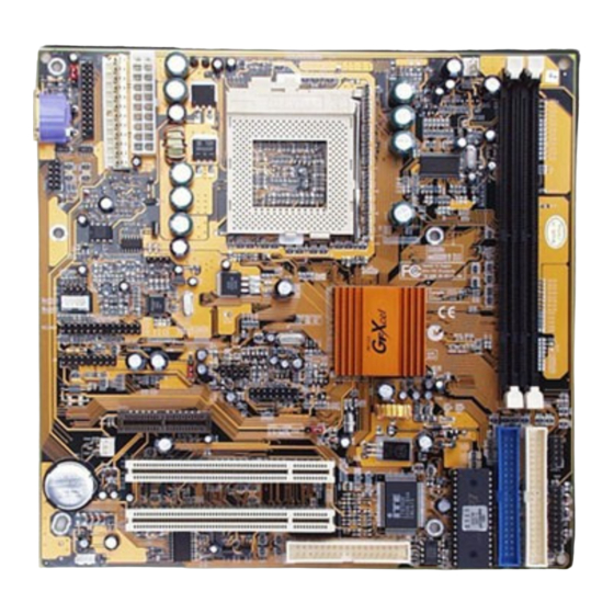
Page 12: Mainboard Components
Mainboard User’s Manual Mainboard Components Use the diagram below to identify the major components on the mainboard. Note: Any jumpers on your mainboard that do not appear in this illustration are for testing only. -
Page 13: Install A Cpu
2: Mainboard Installation Install A CPU This mainboard has a Socket 370 which supports PPGA/FCPGA Celeron and FCPGA Pentium III processors. To ensure reliability, ensure that your processor has a heatsink/cooling fan assembly. Do not try to install a Socket 7 processor in the Socket-370. A Socket 7 processor such as the Pentium-MMX, or the AMD K5/K6 does not fit in the Socket 370. -
Page 14: Install Memory
Mainboard User’s Manual 3. On the Socket-370, identify the Pin-1 corner. The Pin-1 corner is at the end of the locking lever when it is locked. 4. Match the Pin-1 corners and insert the processor into the socket. No force is required and the processor should drop into place freely. -
Page 15: Setting Jumper Switches
2: Mainboard Installation To install a module, push the retaining latches at either end of the socket outwards. Position the memory module correctly and insert it into the DIMM socket. Press the module down into the socket so that the retaining latches rotate up and secure the module in place by fitting into notches on the edge of the module. - Page 16 Mainboard User’s Manual Jumper JP2: Wake On LAN Selector This controls the LAN Wake Up feature where the system will wake up in response to a signal over a LAN it is connected to. Note: The system must provide 1A on the +5VSB (+5V Standby) signal in order for this feature to work.
-
Page 17: Install The Mainboard
2: Mainboard Installation Install the Mainboard Install the mainboard in a system chassis (case). The board is a Baby-AT size mainboard with a set of I/O ports. You can install this mainboard in any AT case. Ensure that your case has an I/O cover plate that matches the ports on this mainboard. -
Page 18: Install The Extension Brackets
Mainboard User’s Manual Install the Extension Brackets The extension brackets are used to connect features on the mainboard to external connectors that can be attached to the system chassis. Follow the steps below to install the extension brackets. Note: All the ribbon cables used on the extension brackets have a red stripe on the Pin-1 side of the cable. - Page 19 2: Mainboard Installation...
- Page 20 Mainboard User’s Manual Serial/Parallel Ports Extension Bracket This bracket has one serial port - COM1 (9-pins) and one parallel port –PRN1 (25pins). On this mainboard, the second serial port is reserved for the Fax/Modem so you can only connect one of the serial ports to the manboard header COM1.
- Page 21 2: Mainboard Installation VGA Extension Bracket The VGA extension bracket has a 15-pin connector for an external monitor cable. VGA1 Header VGA Extension Bracket 1. On the mainboard, locate the VGA1 header for this bracket. 2. Plug the cable from the bracket into the header. 3.
- Page 22 Mainboard User’s Manual LAN Adapter Extension Bracket This bracket supports an RJ45 network connector and connects to the built in LAN header on the mainboard. LAN Header LAN Extension Bracket 1. On the mainboard, locate the LAN header for this bracket. 2.
-
Page 23: Optional Extension Brackets
2: Mainboard Installation Optional Extension Brackets For this mainboard, you can also obtain an ATX form card and a USB module extension bracket. Install them by following the steps below. ATX Form Card This ATX Form Card provides a mini-DIN port for infrared, one mini-DIN port for a PS/2 mouse. - Page 24 Mainboard User’s Manual Extended USB Module This module bracket has two USB ports for more USB devices. USB1 Header 1. Locate the USB1 header on the mainboard. 2. Plug the bracket cable onto the header. 3. In the system chassis, remove a slot cover from one of the expansion slots and install the extension bracket in the opening.
-
Page 25: Install Other Devices
2: Mainboard Installation Install Other Devices Install and connect any other devices in the system following the steps below. FDC1 IDE1 IDE2 Floppy Disk Drive The mainboard ships with a floppy disk drive cable that can support one or two drives. Drives can be 3.5” or 5.25” wide, with capacities of 360K, 720K, 1.2MB, 1.44MB, or 2.88MB. - Page 26 Mainboard User’s Manual If you want to install more IDE devices, you can purchase a second IDE cable and connect one or two devices to the Secondary IDE channel connector IDE2 on the mainboard. If you have two devices on the cable, one must be Master and one must be Slave. Internal Sound Connections If you have installed a CD-ROM drive or DVD-ROM drive, you can connect the drive audio cable to the onboard sound system.
-
Page 27: Expansion Slots
2: Mainboard Installation Expansion Slots This mainboard has two 32-bit PCI expansion slots and one AMR slot. WOL connector SB5V Signal AMR1 PCI2 PCI1 Follow the steps below to install a PCI/AMR expansion card. 1. Locate the AMR or PCI slots on the mainboard. 2. - Page 28 Mainboard User’s Manual allows incoming traffic to resume the system from a software power down. You need to enable this feature in the system setup utility.
- Page 29 2: Mainboard Installation...
-
Page 30: Chapter 3: Bios Setup Utility
3: BIOS Setup Utility Chapter 3 BIOS Setup Utility Introduction The BIOS Setup Utility records settings and information about your computer such as the date and time, the kind of hardware installed, and various configuration settings. Your computer uses this information to initialize all the components when booting up and functions as the basis for coordination between system components. -
Page 31: Running The Setup Utility
Mainboard User’s Manual Running the Setup Utility Each time your computer starts, before the operating system loads, a message appears on the screen that prompts you to “Hit <DEL> if you want to run SETUP”. When you see this message, press the Delete key and the Main menu page of the Setup Utility appears on your monitor. -
Page 32: Standard Cmos Setup Page
3: BIOS Setup Utility Standard CMOS Setup Page Use this page to set basic information such as the date and time, the IDE devices, and the diskette drives. If you press the F3 key, the system will automatically detect and configure the hard disks on the IDE channels. -
Page 33: Advanced Setup Page
Mainboard User’s Manual Advanced Setup Page Use this page to set more advanced information about your system. Take some care with this page. Making changes can affect the operation of your computer. Trend ChipAway This mainboard has built-in virus protection in the Virus firmware. - Page 34 3: BIOS Setup Utility Floppy Drive If you have two diskette drives installed and you Swap enable this item, drive A becomes drive B and drive B becomes drive A. Floppy Drive If you enable this item, your system will check all Seek floppy disk drives at start up.
-
Page 35: Power Management Setup Page
Mainboard User’s Manual Power Management Setup Page This page sets some of the parameters for system power management operation. Power Use this item to enable or disable a power Management/APM management scheme. If you enable power management, you can use the items below to set the power management operation. - Page 36 3: BIOS Setup Utility OnBoard Lan The system can be turned off with a software Power On command. If you enable this item, the system can automatically resume if there is traffic on the network adapter. You must use an ATX power supply in order to use this feature.
-
Page 37: Pci / Plug And Play Setup Page
Mainboard User’s Manual PCI / Plug and Play Setup Page This page sets some of the parameters for devices installed on the PCI bus and devices that use the system plug and play capability. Plug and Play Enable this item if you are using an O/S that supports Plug and Play such as Windows 95 or Aware O/S Primary Graphics... -
Page 38: Load Optimal Settings
3: BIOS Setup Utility Load Optimal Settings If you select this item and press Enter a dialog box appears. If you press Y, and then Enter, the Setup Utility loads a set of fail-safe default values. These default values are not very demanding and they should allow your system to function with most kinds of hardware and memory chips. -
Page 39: Features Setup Page
Mainboard User’s Manual Features Setup Page This page sets some of the parameters for peripheral devices connected to the system. AMIBIOS SETUP – Features SETUP (C) 2000 American Megatrends, Inc. All Rights Reserved OnBoard FDC Enabled OnBoard Serial PortA 3F8h/COM1 OnBoard IR Port Disabled OnBoard Parallel Port... - Page 40 3: BIOS Setup Utility OnBoard Game Use this item to enable or disable the onboard Port Game port. OnBoard MIDI Port Use this item to enable or disable the onboard MIDI port, and to assign a port address. MIDI Port IRQ Use this item to assign an IRQ to the MIDI port.
-
Page 41: Cpu Pnp Setup Page
Mainboard User’s Manual CPU PnP Setup Page This page lets you manually configure the mainboard for the CPU. The system will automatically detect the kind of CPU that you have installed and make the appropriate adjustments to the items on this page. Note: If you manually set the wrong speed and the system won’t run properly, press the Page Up key while the system is booting and a default setting will replace the incorrect CPU setting. -
Page 42: Hardware Monitor Page
3: BIOS Setup Utility Hardware Monitor Page This page sets some of the parameters for the hardware monitoring function of this mainboard. AMIBIOS SETUP – HARDWARE Monitor ©1998 American Megatrends, Inc. All Rights Reserved --- Hardware Monitor --- Socket 370 30°C/86°F Fan#1 Speed Fan#2 Speed... -
Page 43: Exit
Mainboard User’s Manual Change or Remove the Password Highlight this item, press Enter and type in the current password. At the next dialog box, type in the new password, or just press Enter to disable password protection. Exit Highlight this item and press Enter to save the changes that you have made in the Setup Utility configuration and exit the program. -
Page 44: Chapter 4: Software & Applications
4: Software & Applications Chapter 4 Software & Applications Introduction The support software CD-ROM that is included in the mainboard package contains all the drivers and utility programs needed to properly run our products. Below you can find a brief description of each software program, and the location for your mainboard version. - Page 45 Mainboard User’s Manual Note: The correct path name for each software driver is provided, where D: identifies the CD-ROM drive letter – modify if necessary. Bus Master IDE Driver The IDE Bus Master Drivers allows the system to properly manage the IDE channels on the mainboard.
-
Page 46: Installing Under Windows 98
4: Software & Applications BIOS Update Utility The BIOS Update utility allows you to update the BIOS file on the mainboard to a newer version. You can download the latest version of the BIOS setup available for your mainboard from the website. ... - Page 47 Mainboard User’s Manual When you click on the Setup button the software installation program will run and you can select what kind of installation you want to do, as explained later in this section. The Browse CD button is the standard Windows command that allows you to examine the contents of the disc using the Windows 98 file browsing interface.
- Page 48 4: Software & Applications 3. The support software will automatically install. Once any of the installation procedures start, software is automatically installed in sequence. You will need to follow the onscreen instructions, confirm commands and allow the computer to restart as few times as is needed to complete installing whatever software you selected to install.
Need help?
Do you have a question about the M755LMR V7.1 and is the answer not in the manual?
Questions and answers