Table of Contents
Advertisement
This publication, including all photographs, illustrations and
software, is protected under international copyright laws, with all
rights reserved. Neither this manual, nor any of the material
contained herein, may be reproduced without the express written
consent of the manufacturer.
The information in this document is subject to change without
notice. The manufacturer makes no representations or warranties
with respect to the contents hereof and specifically disclaims any
implied warranties of merchantability or fitness for any particular
purpose. Further, the manufacturer reserves the right to revise this
publication and to make changes from time to time in the content
hereof without obligation of the manufacturer to notify any person
of such revision or changes.
Trademarks
IBM, VGA, OS/2, and PS/2 are registered trademarks of
International Business Machines.
Intel, Pentium, Pentium-II, Pentium-III, MMX, and Celeron are
registered trademarks of Intel Corporation.
Microsoft, MS-DOS and Windows 95/98/NT are registered
trademarks of Microsoft Corporation.
Sound Blaster is a trademark of Creative Technology Ltd.
PC-cillin and ChipAwayVirus are trademarks of Trend Micro Inc.
AMI is a trademark of America Megatrends Inc.
A3D is a registered trademark of Aureal Inc.
Gamut is a registered trademark of Formosoft International Inc.
SuperVoice is a registered trademark of Pacific Image
Communications Inc.
MediaRing Talk is a registered trademark of MediaRing Inc.
WordPerfect is a registered trademark of Corel Corporation Ltd.
Other names used in this publication may be trademarks and are
acknowledged.
Copyright © 1999
All Rights Reserved
M726MRT, V1.2
A6T/Junly 1999
Advertisement
Table of Contents

Related Manuals for PC Chips M726MRT


Summary of Contents for PC Chips M726MRT
- Page 1 MediaRing Talk is a registered trademark of MediaRing Inc. WordPerfect is a registered trademark of Corel Corporation Ltd. Other names used in this publication may be trademarks and are acknowledged. Copyright © 1999 All Rights Reserved M726MRT, V1.2 A6T/Junly 1999...
- Page 2 Federal Communications Commission (FCC) Federal Communications Commission (FCC) This equipment has been tested and found to comply with the limits for a Class B digital device, pursuant to Part 15 of the FCC Rules. These limits are designed to provide reasonable protection against harmful interference in a residential installation.
-
Page 3: Table Of Contents
Table of Contents Chapter 1 Introduction..............1 Key Features................. 2 Slot-1 Processor Support............2 Socket-370 Processor Support........... 2 Memory Support............... 2 Expansion Slots ................ 2 Onboard IDE channels .............. 2 Power Supply and Power Management........2 Sound System................3 Onboard I/O Ports..............3 Hardware Monitoring.............. - Page 4 Internal Digital Audio ............. 21 Install Other Devices..............22 Floppy Disk Drive ..............22 IDE Devices ................22 Internal Sound Connections............. 23 Expansion Slots ................23 Chapter 3 BIOS Setup..............25 Introduction ................25 Running the Setup Utility ............25 Standard CMOS Setup Page ............27 Advanced CMOS Setup Page ............
- Page 5 Support and Services ..............A13 Appendix B: Gamut ..............B1 Introduction ................B2 Before Installing ................ B3 Installation ................. B4 Produce MP3 fileUse CD-Cashier ........... B5 Play MP3 fileUse Musician ............ B7 Play music CDUse 3D -ACD ..........B8 Play MIDI fileUse Midier ............B9 Recording audio dataUse Voice-Catcher .......
-
Page 6: Chapter 1 Introduction
Chapter 1 Introduction This mainboard has a slot-1 processor socket for an Intel processor cartridge, and it also has a socket-370 for an Intel PPGA (Plastic Pin Grid Array) Celeron processor. You can install either one of these processors according to the power and performance requirements that you need from your system. -
Page 7: Key Features
Key Features This key features of this mainboard include: Slot-1 Processor Support ♦ Pentium-III support for 450 MHz to 600 MHz clock rates ♦ Pentium-II support for 233 MHz to 450 MHz clock rates ♦ SEPP Celeron support for 266 MHz to 433 MHz clock rates ♦... -
Page 8: Sound System
Sound System ♦ Meets PC98 audio specification ♦ Full duplex playback and recording with built-in 16-bit CODEC ♦ HRTF 3D professional audio supports both Direct Sound 3D® and A3D® compatible interface plus support for 4- channel speakers ♦ Drivers support DOS/Windows 95/98/2000/NT 4.0 ♦... -
Page 9: Fax/Modem Daa Module
Fax/Modem DAA Module ♦ 56 Kbps Fax/Modem DAA module ♦ Supports V.90, V.34, V.32bis, V.32, V.22bis, V.22 ♦ Supports Auto Fallback and MNP 5, V.42bis data compression with 115200 compatible Virtual UART ♦ Requires 16 MB RAM and WIN 95/98/NT Onboard Flash ROM ♦... -
Page 10: Package Contents
Package Contents Your mainboard package ships with the following items: Mainboard This User’s guide IDE cable Floppy diskette drive cable Audio ports and Game/MIDI port extension bracket Serial ports extension bracket Parallel port extension bracket V.90 Fax/Modem DAA module Support software CD-ROM Optional Accessories You can purchase the following optional accessories for this mainboard. -
Page 11: Static Electricity Precautions
Static Electricity Precautions 1. Components on this mainboard can be damaged by static electricity. Take the following precautions when unpacking the mainboard and installing it in a system. 2. Keep the mainboard, and other components, in their original static-proof packaging until you are ready to install them. 3. -
Page 12: Chapter 2 Mainboard Installation
Chapter 2 Mainboard Installation To install this mainboard into your system, follow the procedures in this chapter: Identify the mainboard components Install the correct processor Install one or more memory modules Verify that any jumpers or switches are at the correct setting Install the mainboard in the system chassis Install any extension cables to the mainboard headers Install any other devices and make the appropriate connections... -
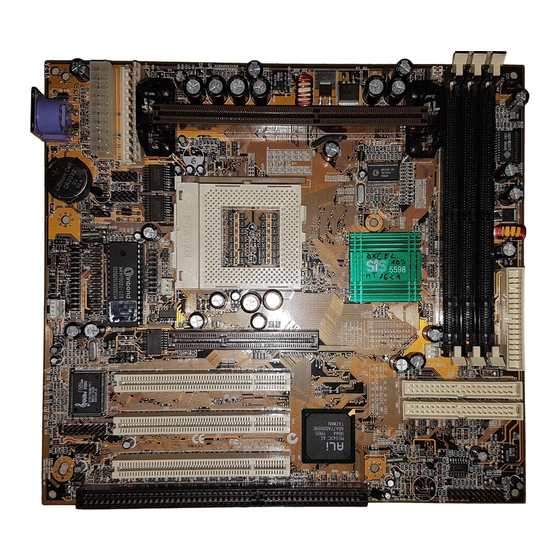
Page 13: Mainboard Components
Mainboard Components Use the diagram below to identify the major components on your mainboard. Note: Any jumpers on your mainboard that do not appear in this illustration are for testing only. -
Page 14: Install The Processor
Install the Processor This mainboard has a Slot-1 that can be installed with any Slot-1 processor cartridge including the Pentium-III, Pentium-II, and the SEPP Celeron. It also has a Socket-370 that can be installed with the Celeron processor which is shipped in a PPGA (Plastic Pin Grid Array) package. -
Page 15: Installing A Slot-1 Processor Cartridge
Installing a Slot-1 Processor Cartridge 1. Locate Slot-1, and FAN1 on the mainboard. FAN1 Slot-1 with pre-installed cartridge holder. The upright arms are folded down for shipping. 2. The Slot-1 is installed with a cartridge holder. The upright struts of the cartridge holder are folded down for shipping. Pull the struts upwards so that they are in the upright position. -
Page 16: Installing A Socket-370 Processor
Installing a Socket-370 Processor The Celeron processor installs into the ZIF (Zero Insertion Force) Socket-370 on the mainboard. 1. Locate the Socket-370, and FAN1. Pull the locking lever out from the socket and swing it to the upright position. Socket-370 Pin-1 Corner FAN1 2. -
Page 17: Jumper Jp7: Bus Frequency Selector
Jumper JP7: Bus Frequency Selector This jumper consists of two sets of 3-pin jumpers JP7B and JP7A. Use JP7 to select the following system bus frequency. Function JP7B Setting JP7A Setting 66 MHz Short Pins 1-2 Short Pins 2-3 75 MHz Short Pins 2-3 Short Pins 2-3 100 MHz... -
Page 18: Install Memory
Install Memory The mainboard has three DIMM slots which can be installed with memory modules. You must install at least one memory module in order to use the mainboard. DIMM3 DIMM2 DIMM1 For this mainboard, you must use 168-pin, memory modules installed with SDRAM/EDO/FP memory chips. -
Page 19: Set The Jumpers
Set the Jumpers Jumpers are sets of pins that can be connected together with jumper caps. The jumper caps change the way the mainboard operates by changing the electronic circuits on the mainboard. If a jumper cap connects two pins, we say the pins are SHORT. If a jumper cap is removed from two pins, the pins are OPEN. -
Page 20: Jumper Jp4: Clear Cmos Memory
Jumper JP4: Clear CMOS Memory Use this jumper to clear the contents of the CMOS memory. You may need to clear the CMOS memory if the settings in the setup utility are incorrect and prevent your mainboard from operating. To clear the CMOS memory, disconnect all the power cables from the mainboard and then move the jumper cap into the CLEAR setting for a few seconds. - Page 21 FAN2 ATX-PW1 AT-PW2 Connect the power cable from the power supply unit to the power connector on the mainboard. If you are using an AT power unit, connect it to the AT power connector PW2. If you are using an ATX power unit connect it to the ATX power connector PW1.
-
Page 22: Install The Extension Brackets
Install the Extension Brackets The extension brackets are used to transmit features on the mainboard to external connectors that can be fixed to the system chassis. Follow the steps below to install the extension brackets. Note: All the ribbon cables used on the extension brackets carry a red stripe on the pin-1 side of the cable. -
Page 23: Serial Ports Extension Bracket
Serial Ports Extension Bracket This bracket has two serial ports; COM1 (9-pins) and COM2 (25pins). 1. On the mainboard, locate the two headers COM1 and COM2 for this bracket. 2. Plug the two cables from the bracket into the appropriate COM1 and COM2 headers. -
Page 24: Parallel Port Extension Bracket
Parallel Port Extension Bracket This bracket has one parallel port LPT1. PRN1 Parallel port LPT1 Parallel Port Extension Bracket 1. On the mainboard, locate the parallel port headers PRN1 for this bracket. 2. Plug the cable from the bracket into the PRN1 header. 3. -
Page 25: Optional Extension Brackets
1. Locate the J3 modem header on the mainboard. 2. Plug the Fax/Modem DAA module into the J3 modem header. 3. Remove the blanking plate adjacent to the Fax/Modem DAA module. Line & Tel RJ11 phone Modem DAA Module jacks Modem Header Optional Extension Brackets For this mainboard, you can also obtain an ATX Form Card and an... -
Page 26: Optic Module Extension Bracket
1. On the mainboard, locate the J5 ATX header for this bracket. 2. Plug the cable from the bracket into the J5 ATX header. 3. In the system chassis, remove a blanking plate from one of the expansion slots and install the extension bracket in the slot. Use the screw that held the blanking plate in place to secure the extension bracket. -
Page 27: Install Other Devices
Install Other Devices Install and connect any other devices in the system following the steps below. Floppy Disk Drive The mainboard ships with a floppy disk drive cable that can support one or two drives. Drives can be 3.5” or 5.25” wide, with capacities of 360K, 720K, 1.2MB, 1.44MB, or 2.88MB. -
Page 28: Internal Sound Connections
Install the device(s) and supply power from the system power unit. Use the cable provided to connect the device(s) to the Primary IDE channel connector IDE1 on the mainboard. If you want to install more IDE devices, you can purchase a second IDE cable and connect one or two devices to the Secondary IDE channel connector IDE2 on the mainboard. - Page 29 PCI3 PCI1 PCI2 ISA1 Follow the steps below to install an add-in card into one of the slots. 1. Determine which slot you need to use. The table below shows the functions of the slots. AGP stands for Accelerated Graphics Port. Use this slot to install a graphics adapter which has an AGP edge connector.
-
Page 30: Chapter 3 Bios Setup
Chapter 3 BIOS Setup Introduction The BIOS setup utility stores information about your computer such as the date and time, the kind of hardware you have installed, and so on. Your computer uses this information to initialize all the components at boot up time, and make sure that everything runs smoothly. - Page 31 You can use the cursor arrow keys to highlight any of the options on the Mainmenu page. Press Enter to select the highlighted option. To leave the setup utility, press the Escape key. Hold down the Shift key and press F2 to cycle through the optional color schemes of the setup utility.
-
Page 32: Standard Cmos Setup Page
Standard CMOS Setup Page Use this page to set basic information such as the date and time, the IDE devices, and the diskette drives. Date & Time Use these items to install your system with the correct date and time Pri Master Use these items to configure devices on the Pri Slave... -
Page 33: Advanced Cmos Setup Page
Advanced COMS Setup Page Use this page to set more advanced information about your system. Take some care with this page. Making changes can affect the operation of your computer. Quick Boot If you enable this item, the system starts up more quickly be elimination some of the power on test routines. - Page 34 Floppy Drive If you enable this item, your system will check the Seek diskette drives at start up time. Disable this item unless you are using an old 360K diskette drive. PS/2 Mouse Set this item to auto so that it will automatically Support detect if you are using a mouse with a PS/2 interface.
-
Page 35: Advanced Chipset Setup Page
Advanced Chipset Setup Page This page lets you set some of the timing parameters for the system. Trend ChipAway This mainboard has built-in virus protection in the Virus firmware. Use this item to enable or disable the built-in virus protection. Bank X SDRAM The three items which define the timing for /DEO/FPM... -
Page 36: Power Management Setup Page
USWC Memory This item sets the memory gap size for USWC Gap Size (Un-cacheable Speculative Write Combining) mode. AT Bus Clock This item sets the clock speed for the AT ISA bus. ISA Line Buffer Use this item to enable or disable the line buffer for the ISA bus. - Page 37 Note: Some of the power management routines are not functional if you have connected the mainboard to an AT power supply, rather than an ATX power supply. Power Use this item to enable or disable the power Management/APM management routines. If you enable the power management, you can use the items below to set the power management operation.
-
Page 38: Pci / Plug And Play Setup Page
Resume From Soft the system realtime clock that will resume the system from a power-saving mode or a software power down. RTC Alarm Date / If you have enabled the RTC Alarm Power on, Hour / Minute / use these items to set the time and date of the Second alarm. -
Page 39: Load Optimal Settings
Offboard PCI IDE If you are using an IDE interface add-in card, Card use this item to define which PCI slot the card is installed in. Leave this item at Auto for automatic detection. Pri. / Sec. Offboard If you are using an IDE interface add-in card, PCI IDE IRQ use these items to assign an IRQ to the primary and secondary IDE channels. -
Page 40: Peripheral Setup Page
quite demanding and your system might not function properly if you are using slower memory chips or other kinds of low- performance components. Peripheral Setup Page This page sets some of the parameters for peripheral devices installed on the system. Onboard FDC Use this item to enable or disable the onboard floppy disk drive interface. - Page 41 Onboard IR Port Use this item to determine the allocation of the resources of the second serial port. If you select IR items normal, the resources are assigned to the optional second serial port. If you select a specific address, the resources are assigned to the IR port, and you can use the five items below to determine the operation of the IR port.
-
Page 42: Hardware Monitor Status Page
Hardware Monitor Status Page This page displays the parameters for hardware monitoring. Slot 1 / Socket 370 Use these items to monitor the threshold / System Temp. temperature for the CPU and the system. FANs & voltages Use these items to monitor the parameters for the fan speeds and the mainboard voltages. -
Page 43: Auto-Detect Hard Disks
Auto-Detect Hard Disks This item automatically detects and installs any hard disk drives installed on the primary and secondary IDE channel. Most modern drives can be detected. If you are using a very old drive that can’t be detected, you can install it manually. Setup will check for two devices on the primary IDE channel and then two devices on the secondary IDE channel. -
Page 44: Chapter 4 Software & Applications
The IDE Bus Master Driver allows the system to properly manage the IDE channels on the mainboard. You need to install an IDE driver if you are running Windows 9X/NT. ♦ Windows 9X – D:\IDE\M726MRT\WIN9X\SETUP.EXE ♦ Windows NT4.0 – D:\IDE\M726MRT\NT40 AGP Driver The AGP Driver allows the system to properly manage the AGP slot on the mainboard. -
Page 45: Sound Driver And Applications
♦ Windows 95 – D:\USB\EUSBSUPP\USBSUPP.EXE ♦ Windows 95 (Chinese) – D:\USB\CUSBSUPP\CUSBSUPP.EXE Sound Driver and Applications The Sound driver allows the system to generate optimal sound effects. This driver is available for: ♦ DOS & Windows 3.x – D:\SOUND\DRIVER\8738AM\DOS- ♦ Windows 9X – D:\SOUND\DRIVER\8738AM\W95-98 ♦... -
Page 46: Using The Pci Sound Application
D:\AMIADCM\WIN95&98\SETUP.EXE Using the PCI Sound Pro Application 1. Before you install the PCI Sound Pro drivers, make sure your Operating System has been installed, otherwise the PCI Sound Pro might be detected as “Other device” by the device manager of your OS. 2. -
Page 47: Speaker Position
in/Rear jack on the sound ports extension bracket. The original Line-in can be moved to Aux. Speaker Position Set up your speakers similar to the following figure to get the best audio result. Mixer Setup There is a 4-speakers option in the Volume Control of the Mixer when you are setting up the PCI Audio Application.
Need help?
Do you have a question about the M726MRT and is the answer not in the manual?
Questions and answers