Table of Contents
Advertisement
Table of Contents
Table of Contents............................................................................ 1
Chapter 1........................................................................................ 4
Introduction................................................................................. 4
Key Features.......................................................................................5
Socket-7 Processor Support........................................................... 5
Memory Support............................................................................ 5
Expansion Slots............................................................................. 5
Onboard IDE channels...................................................................5
Power Supply and Power Management......................................... 5
Built-in Graphics System...............................................................6
Sound System................................................................................ 6
Onboard I/O Ports..........................................................................6
Hardware Monitoring.................................................................... 6
Built-in LAN .................................................................................7
Fax/Modem DAA Module.............................................................7
Onboard Flash ROM......................................................................7
Bundled Software.......................................................................... 7
Dimensions.................................................................................... 8
Package Contents............................................................................... 8
Optional Accessories..................................................................... 8
Static Electricity Precautions............................................................. 9
Chapter 2...................................................................................... 10
Mainboard Installation.............................................................. 10
Mainboard Components................................................................... 11
Install the Processor........................................................................ 12
Install Memory................................................................................. 13
Set the Jumpers................................................................................ 14
Jumper JP3: Clear CMOS Memory............................................. 14
Jumper JP2: Keyboard Power On Selector..................................15
Jumper JP6: LAN Enable/disable Selector .................................15
Jumper JP8: Audio System Enable/disable................................. 15
Jumper JP10: Fax/Modem Enable/disable...................................16
Install the Mainboard....................................................................... 16
Install the Extension Brackets/Options............................................ 18
Audio Ports and Game/MIDI Port Extension Bracket................ 18
Serial/Parallel Ports Extension Bracket....................................... 19
VGA Extension Bracket.............................................................. 20
LAN Network Adapter Extension Bracket..................................21
Fax/Modem DAA Module...........................................................22
Advertisement
Table of Contents

Related Manuals for PC Chips M598LMR


Summary of Contents for PC Chips M598LMR
-
Page 1: Table Of Contents
Table of Contents Table of Contents................1 Chapter 1..................4 Introduction................. 4 Key Features..................5 Socket-7 Processor Support............5 Memory Support................5 Expansion Slots................5 Onboard IDE channels..............5 Power Supply and Power Management......... 5 Built-in Graphics System...............6 Sound System................6 Onboard I/O Ports................6 Hardware Monitoring.............. - Page 2 Optional Digital Audio Extension Bracket........23 Internal Digital Audio..............23 Optional ATX Form Card ............24 Optional Infrared Port..............25 Install Other Devices................26 Floppy Disk Drive............... 26 IDE Devices.................26 Internal Analog Sound Connections..........27 Expansion Slots................28 Installing an Expansion Card............28 Wake On LAN Connector............29 Chapter 3..................
- Page 3 Using the PCI Sound Pro Application..........46 The Four Speakers System...............47 Speaker Installation..............47 Speaker Position................47 Trademarks..................48 Federal Communications Commission (FCC)......... 49 Canadian Department of Communications........49 Appendix A: Corel WordPerfect Suite 8 ........A1 Welcome to Corel WordPerfect Suite 8 .........A2 Installing Corel WordPerfect Suite 8 ..........
-
Page 4: Chapter 1
Chapter 1 Introduction This mainboard uses the SiS530 chipset to leverage extra performance from the Socket-7 architecture. The mainboard supports all Socket-7 processors including newer designs which feature a 100 MHz system bus. The mainboard firmware supports CPU Plug and Play so that the system will automatically adopt the correct configuration for the Socket-7 processor that you install. -
Page 5: Key Features
Key Features This key features of this mainboard include: Socket-7 Processor Support ♦ Supports all recent socket-7 processors including Intel P55C (Pentium MMX), Cyrix/IBM 6x86L/6x86MX/M-II, AMD K6/K6-2/K6-III, and IDT C6 and WinChip 2/2A CPUs ♦ Supports socket-7 processors with system bus frequencies of 60/66/75/83/95/100 MHz ♦... -
Page 6: Built-In Graphics System
Built-in Graphics System ♦ Onboard 64-bit 3D AGP Graphics Accelerator ♦ Complies with AGP Ver.1 with 66/133 MHz operation ♦ Shared memory architecture allows a maximum of 8 MB main memory to act as frame buffer ♦ Supports high resolutions up to 1600 x 1200 pixels Sound System ♦... -
Page 7: Built-In Lan
♦ Supports AMI’s Desktop Client Manager (ADCM) Built-in LAN ♦ Onboard 10BaseT/100BaseTX LAN ♦ LAN controller integrates Fast Ethernet MAC and PHY compliant with IEEE802.3u 100BASE-TX, 10BASE-T and ANSI X3T12 TP-PMD standards ♦ Compliant with ACPI 1.0 and the Network Device Class Power Management 1.0 ♦... -
Page 8: Dimensions
♦ WordPerfect Suite 8 is a windows version office application Dimensions ♦ Baby-AT form factor (22cm x 22cm) Package Contents Your mainboard package ships with the following items: Mainboard This User’s guide IDE cable Floppy diskette drive cable ... -
Page 9: Static Electricity Precautions
Static Electricity Precautions 1. Components on this mainboard can be damaged by static electricity. Take the following precautions when unpacking the mainboard and installing it in a system. 2. Keep the mainboard, and other components, in their original static-proof packaging until you are ready to install them. 3. -
Page 10: Chapter 2
Chapter 2 Mainboard Installation To install this mainboard into your system, follow the procedures in this chapter: Identify the mainboard components Install the correct processor Install one or more memory modules Verify that any jumpers or switches are at the correct setting ... -
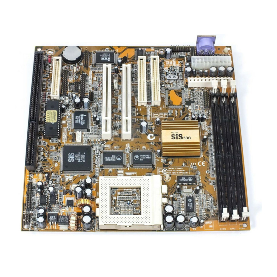
Page 11: Mainboard Components
Mainboard Components Use the diagram below to identify the major components on your mainboard. Note: Any jumpers on your mainboard that do not appear in this illustration are for testing only. -
Page 12: Install The Processor
Install the Processor This mainboard is installed with a socket-7, and so it may be installed with any of the socket-7 processors including the Intel P55C (MMX) series, the Cyrix/IBM 6x86L/6x86MX/M-II series, the AMD K6/K6-2/K6-III series, and the IDT C6/Winchip 2/2A series. -
Page 13: Install Memory
3. On the socket-7, identify the pin-1 corner. The pin-1 corner is on the same side as the locking lever, closest to the top of the lever when it is in the locked position. 4. Match the pin-1 corners and insert the socket-7 processor into the socket. -
Page 14: Set The Jumpers
You can install any size of memory module from 16 MB up to 256 MB, so the maximum memory size is 3 x 256 MB = 768 MB. The edge connectors on the memory modules have cut outs, which coincide with struts in the DIMM slots, so the memory modules can only be installed in the correct way. -
Page 15: Jumper Jp2: Keyboard Power On Selector
Function Jumper Setting Normal Operation Short Pins 1-2 Clear CMOS memory Short Pins 2-3 Note: The mainboard ships with this jumper in the CLEAR position so you must change this jumper to NORMAL. Jumper JP2: Keyboard Power On Selector If you are using an ATX power supply unit, you can use hot keys on your keyboard as a power on/off switch for the system. -
Page 16: Jumper Jp10: Fax/Modem Enable/Disable
Jumper JP10: Fax/Modem Enable/disable Use this jumper to enable or disable the onboard Fax/Modem. Disable the Fax/Modem if you plan on using another Fax/Modem. Function Jumper Setting Enable Fax/Modem Short Pins 2-3 Disable Fax/Modem Short Pins 1-2 Note: If you have disabled the onboard audio system with jumper JP8, the Fax/Modem will not function even if it is enabled. - Page 17 connect it to the AT power connector PWR1. If you are using an ATX power unit connect it to the ATX power connector PWR2. Connect the case switches and indicator LEDs to the bank of switch and LED connectors J2. See the illustration below for a guide to the pin functions of the J2 connector.
-
Page 18: Install The Extension Brackets/Options
Install the Extension Brackets/Options The modules and extension brackets are used to transmit features on the mainboard to external connectors that can be fixed to the system chassis. Follow the steps below to install the extension brackets. Note: All the ribbon cables used on the extension brackets carry a red stripe on the pin-1 side of the cable. -
Page 19: Serial/Parallel Ports Extension Bracket
Serial/Parallel Ports Extension Bracket This bracket has one serial port - COM1 (9-pins) and one parallel port – LPT1 (25pins). COM1 Header PRN1- Parallel Port Header Serial Port COM1 Parallel Port LPT1 Serial/Parallel Ports Extension Bracket 1. On the mainboard, locate the headers COM1 and PRN1 for this bracket. -
Page 20: Vga Extension Bracket
VGA Extension Bracket The VGA extension bracket has a 15-pin connector for an external monitor cable. VGA1-VGA Header VGA Extension Bracket 1. On the mainboard, locate the VGA1 header for this bracket. 2. Plug the cable from the bracket into the VGA1 header. 3. -
Page 21: Lan Network Adapter Extension Bracket
LAN Network Adapter Extension Bracket This bracket supports an RJ45 network connector and connects to the built in LAN header LAN1 on the mainboard. LAN1 LAN Header LAN Extension Bracket 1. On the mainboard, locate the LAN1 LAN header for this bracket. -
Page 22: Fax/Modem Daa Module
Fax/Modem DAA Module The Fax/Modem DAA module plugs directly into the mainboard adjacent to an expansion slot in the system chassis. When you remove the blanking plate from the system chassis, you can access the LINE and TEL RJ11 connectors on the metal edge of the Fax/Modem DAA module. -
Page 23: Optional Digital Audio Extension Bracket
Optional Digital Audio Extension Bracket This bracket has two RCA jacks for digital audio in and digital audio out, and an auxiliary jack for a stereo line-in device. It also provides a pair of optic fiber interface which enables the communication with MiniDisk or high-end audio systems. -
Page 24: Optional Atx Form Card
Optional ATX Form Card This ATX Form card provides a mini-DIN port for infrared, one mini-DIN port for a PS/2 mouse. In addition it has two USB (Universal Serial Bus) ports. J1-ATX Header Infrared Port PS/2 Mouse Port USB Ports ATX Form Card 1. -
Page 25: Optional Infrared Port
Optional Infrared Port The mainboard has an infrared header IR1 so that you can install an optional serial infrared port. IR1 Infrared Header 1. On the mainboard locate the infrared port header IR1. 2. Connect the ribbon cable from the port to the header IR1 and then secure the port to an appropriate place in your system chassis. -
Page 26: Install Other Devices
Install Other Devices Install and connect any other devices in the system following the steps below. FDD1 IDE1 IDE2 Floppy Disk Drive The mainboard ships with a floppy disk drive cable that can support one or two drives. Drives can be 3.5” or 5.25” wide, with capacities of 360K, 720K, 1.2MB, 1.44MB, or 2.88MB. -
Page 27: Internal Analog Sound Connections
If you want to install more IDE devices, you can purchase a second IDE cable and connect one or two devices to the Secondary IDE channel connector IDE on the mainboard. If you have two devices on the cable, one must be Master and one must be Slave. Internal Analog Sound Connections If you have installed a CD-ROM drive or a DVD drive, you can connect the sound output of the drive to the built-in sound system. -
Page 28: Expansion Slots
Expansion Slots This mainboard has two PCI 32-bit expansion slots and one 8/16- bit ISA slot. PCI1 ISA1 PCI2 Use the PCI slots to install 32-bit PCI expansion cards. Use the ISA slot to install legacy 8/16-bit expansion cards. Note: The PCI2 slot can only be used if you disable the onboard LAN network using jumper JP6. -
Page 29: Wake On Lan Connector
Wake On LAN Connector If you have installed a network adapter card, connect the adapter to the wake on LAN connector J8. You can then use the setup utility to program your computer to resume from a power saving mode whenever there is traffic through the network. -
Page 30: Chapter 3
Chapter 3 BIOS Setup Introduction The BIOS setup utility stores information about your computer such as the date and time, the kind of hardware you have installed, and so on. Your computer uses this information to initialize all the components at boot up time, and make sure that everything runs smoothly. -
Page 31: Running The Setup Utility
Running the Setup Utility Each time your computer starts, before the operating system is booted, a message appears on the screen that prompts “Hit <DEL> if you want to run SETUP”. When you see this message, press the Delete key and the Mainmenu page of the setup utility appears on your monitor. -
Page 32: Standard Cmos Setup Page
with a set of default values. Press F7 to install the setup utility with a set of best-performance values. Standard CMOS Setup Page Use this page to set basic information such as the date and time, the IDE devices, and the diskette drives. If you press the F3 key, the system will automatically detect and configure the hard disks on the IDE channels. -
Page 33: Advanced Setup Page
Advanced Setup Page Use this page to set more advanced information about your system. Take some care with this page. Making changes can affect the operation of your computer. Trend ChipAway This mainboard has built-in virus protection in the firmware. Use this item to enable or disable the Virus built-in virus protection. - Page 34 Floppy Drive If you have two diskette drives installed and you Swap enable this item, drive A becomes drive B and drive B becomes drive A. Floppy Drive If you enable this item, your system will check the diskette drives at start up time. Disable this item Seek unless you are using an old 360K diskette drive.
-
Page 35: Power Management Setup Page
Power Management Setup Page This page sets some of the parameters for the system power management operation. Power Use this item to enable or disable the power Management/APM management routines. If you enable the power management, you can use the items below to set the power management operation. -
Page 36: Pci / Plug And Play Setup Page
Ring On Power On Your system can enter a software power down. If you enable this item, the system can automatically resume if there is an incoming call on the built-in Fax/Modem. RTC Alarm Power Your system can enter a software power down. If you enable this item, the system can automatically resume at a fixed time on the system’s RTC (realtime clock). -
Page 37: Load Optimal Settings
PCI VGA Palette When this item is enabled, multiple VGA Snoop devices operating on different buses can handle data from the CPU on each set of palette registers on every video device. Assign IRQ for If this item is enabled, an IRQ will be assigned to the PCI VGA graphics system. -
Page 38: Features Setup Page
Features Setup Page This page sets some of the parameters for peripheral devices installed on the system. Onboard FDC Use this item to enable or disable the onboard floppy disk drive interface. Onboard Serial Use this item to enable or disable the onboard Port1 serial port COM1, and to assign a port address Onboard IR Port... -
Page 39: Cpu Pnp Setup Page
Onboard PCI IDE Use this item to enable or disable either of the two onboard IDE channels, Primary or Secondary. USB Function Use this item to enable or disable the USB (Universal Bus Ports) that are integrated on this mainboard. USB Function for If you have enabled the USB function, use this item to enable or disable USB when you are... -
Page 40: Hardware Monitor Page
processor that you have installed. CPU Speed Use this item to define the clock speed of the processor that you have installed. CPU Base Use this item to define the system bus frequency that is supported by the processor Frequency that you have installed. -
Page 41: Change Password
VCCs voltages that control the fans and the CPU core. If the values deviate by an amount greater than the values installed here, the hardware monitoring will alert you with a warning. Change Password If you highlight this item and press Enter, a dialog box appears which lets you enter a Supervisor password. -
Page 42: Chapter 4
Chapter 4 Software & Applications Introduction The support software CD-ROM included in the mainboard package contains all the drivers and utilities as needed to use our products. Below you can find a brief description of each software program, and the right location for your mainboard. More information on each individual software might be available in a README file, located in the same directory as the software. -
Page 43: Bus Master Ide Driver
3. Use either My Computer or Windows Explorer to look at the directory structure. You must use the Open command. Double- clicking on the drive icon will not work. 4. Execute the EXE file name given in the description below. Note: The correct path name for each software driver is provided, where D: identifies the CD-ROM drive letter –... -
Page 44: Bios Update Utility
BIOS Update Utility The BIOS Update utility allows you to update the BIOS setup file on your mainboard to a newer version. You can download the latest version of the BIOS setup available for your mainboard from the website. ♦ D:\UTILITY\AMIFL816.EXE PC-Cillin Software The PC-Cillin software program provides anti-virus protection for your system. - Page 45 Please follow the steps listed below to install drivers and applications for your system. 1. Put the support CD into CD-ROM drive. 2. The setup window will appear as below. 3. Click Setup button to continue. 4. Click Next button to continue. 5.
-
Page 46: Using The Pci Sound Pro Application
6. The support software will automatically install. Once any of the installation procedures start, software is automatically installed in sequence. You will need to follow the onscreen instructions, confirm commands and allow the computer to restart as few times as is needed to complete installing whatever software you selected to install. -
Page 47: The Four Speakers System
The Four Speakers System The onboard Sound audio system supports 2 wave channels (front/rear) known as the 4 speaker system. If you are running applications which use the DirectSound® 3D or A3D® audio interface, your system can simulate realistic 3D sound through a 4 speaker setup. -
Page 48: Trademarks
MediaRing Talk is a registered trademark of MediaRing Inc. WordPerfect is a registered trademark of Corel Corporation Ltd. Other names used in this publication may be trademarks and are acknowledged. Copyright © 2000 All Rights Reserved M598LMR, V1.3A S53T/March 2000... -
Page 49: Federal Communications Commission (Fcc)
Federal Communications Commission (FCC) This equipment has been tested and found to comply with the limits for a Class B digital device, pursuant to Part 15 of the FCC Rules. These limits are designed to provide reasonable protection against harmful interference in a residential installation.
Need help?
Do you have a question about the M598LMR and is the answer not in the manual?
Questions and answers