Table of Contents
Advertisement
Quick Links
Table of Contents
Chapter 1 Introduction ..........................................................1
Key Features..................................................................................... 2
Slot-1 Processor Support.............................................................. 2
Socket-370 Processor Support ..................................................... 2
Memory Support .......................................................................... 2
Expansion Slots............................................................................ 2
Onboard IDE channels ................................................................. 2
Power Supply and Power Management........................................ 2
Built-in Graphics System ............................................................. 3
Sound System............................................................................... 3
Onboard I/O Ports ........................................................................ 3
Hardware Monitoring................................................................... 4
Built-in LAN Adapter .................................................................. 4
Fax/Modem DAA Module ........................................................... 4
Onboard Flash ROM .................................................................... 4
Bundled Software......................................................................... 4
Dimensions................................................................................... 5
Package Contents.............................................................................. 5
Optional Accessories.................................................................... 5
Static Electricity Precautions............................................................ 6
Chapter 2 Mainboard Installation.........................................7
Mainboard Components ................................................................... 8
Install the Processor.......................................................................... 9
Installing a Slot-1 Processor Cartridge....................................... 10
Installing a Socket-370 Processor .............................................. 11
Install Memory ............................................................................... 12
Set the Jumpers............................................................................... 13
Jumper JP1: Keyboard Power On Selector ................................ 13
Jumper JP9: Clear CMOS Memory............................................ 14
Enable/Disable ........................................................................... 14
Jumper JP13: Enable/Disable Onboard LAN............................. 14
Install the Mainboard...................................................................... 15
Install the Extension Brackets ........................................................ 17
Audio Ports and Game/MIDI Port Extension Bracket ............... 17
Serial/Parallel Ports Extension Bracket...................................... 18
LAN Adapter Extension Bracket ............................................... 19
Fax/Modem DAA Module ......................................................... 19
Advertisement
Table of Contents

Related Manuals for PC Chips M766LMRT


Summary of Contents for PC Chips M766LMRT
-
Page 1: Table Of Contents
Table of Contents Chapter 1 Introduction ............1 Key Features..................2 Slot-1 Processor Support.............. 2 Socket-370 Processor Support ............. 2 Memory Support ................2 Expansion Slots................2 Onboard IDE channels ..............2 Power Supply and Power Management........2 Built-in Graphics System ............. 3 Sound System................ - Page 2 Table of Contents VGA Extension Bracket............. 20 Optional Extension Brackets ............21 ATX Form Card ................. 21 Digital Audio Extension Bracket ..........22 Internal Digital Audio ..............22 AV/S-Video Output Extension Bracket ........23 Install Other Devices ..............24 Floppy Disk Drive..............24 IDE Devices ................
- Page 3 Table of Contents Speaker Installation..............42 Speaker Position................. 42 Mixer Setup................42 Demo..................43 Appendix A: Corel WordPerfect Suite 8 ......A1 Welcome to Corel WordPerfect Suite 8 ........A2 Installing Corel WordPerfect Suite 8 ..........A6 Learning how to use Corel WordPerfect Suite 8 ......A9 Support and Services ..............
- Page 4 MediaRing Talk is a registered trademark of MediaRing Inc. WordPerfect is a registered trademark of Corel Corporation Ltd. Other names used in this publication may be trademarks and are acknowledged. Copyright © 1999 All Rights Reserved M766LMRT , V1.3 i6T/June 1999...
-
Page 5: Declaration Of Conformity
Federal Communications Commission (FCC) This equipment has been tested and found to comply with the limits for a Class B digital device, pursuant to Part 15 of the FCC Rules. These limits are designed to provide reasonable protection against harmful interference in a residential installation. -
Page 6: Chapter 1 Introduction
Chapter 1 Introduction This mainboard has a slot-1 processor socket for an Intel processor cartridge, and it also has a socket-370 for an Intel PPGA (Plastic Pin Grid Array) Celeron processor. You can install either one of these processors according to the power and performance requirements that you need from your system. -
Page 7: Key Features
Chapter 1 Key Features This key features of this mainboard include: Processors Support ♦ Pentium-III support for 450 MHz to 600 MHz clock rates ♦ Pentium-II support for 233 MHz to 450 MHz clock rates ♦ SEPP Celeron support for 266 MHz to 433 MHz clock rates ♦... -
Page 8: Built-In Graphics System
Key Features Built-in Graphics System ♦ 3D Hyper Pipelined Architecture: Parallel Data Processing (PDP) and Precise Pixel Interpolation (PPI). ♦ Full 2D H/W and Motion Video Acceleration ♦ Up to 1600x1200 in 8-bit color at 85Hz refresh ♦ H/W Motion Compensation Assistance for S/W MPEG2 decode ♦... -
Page 9: Hardware Monitoring
Chapter 1 Hardware Monitoring ♦ Built-in hardware monitoring for CPU/system temperatures, fan speeds and mainboard voltages ♦ Supports AMI’s Desktop Client Manager (ADCM) Built-in LAN Adapter ♦ Onboard 10BaseT/100BaseTX LAN Adapter ♦ LAN controller integrates Fast Ethernet MAC and PHY compliant with IEEE802.3u 100BASE-TX, 10BASE-T and ANSI X3T12 TP-PMD standards ♦... -
Page 10: Dimensions
Package Contents ♦ Media Ring Talk provides PC to PC base internet phone communication ♦ Gamut provides professional audio applications included MP3 encoding/playback ♦ WordPerfect Suite 8 is a windows version office application Dimensions ♦ Baby-AT form factor (22cm x 25.7cm) Package Contents Your mainboard package ships with the following items: Mainboard... -
Page 11: Static Electricity Precautions
Chapter 1 Static Electricity Precautions 1. Components on this mainboard can be damaged by static electricity. Take the following precautions when unpacking the mainboard and installing it in a system. 2. Keep the mainboard, and other components, in their original static-proof packaging until you are ready to install them. -
Page 12: Chapter 2 Mainboard Installation
Chapter 2 Mainboard Installation To install this mainboard into your system, follow the procedures in this chapter: Identify the mainboard components Install the correct processor Install one or more memory modules Verify that any jumpers or switches are at the correct setting Install the mainboard in the system chassis Install any extension cables to the mainboard headers Install any other devices and make the appropriate connections... -
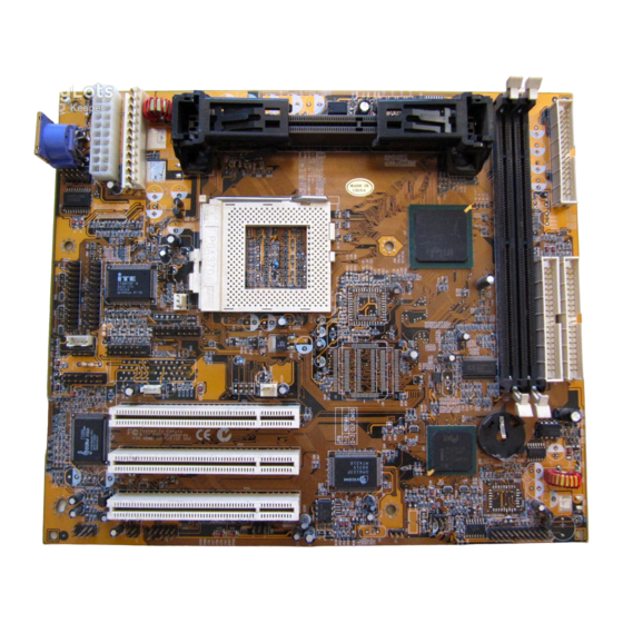
Page 13: Mainboard Components
Chapter 2 Mainboard Components Use the diagram below to identify the major components on your mainboard. Note: Any jumpers on your mainboard that do not appear in this illustration are for testing only. -
Page 14: Install The Processor
Install the Processor Install the Processor This mainboard has a Slot-1 which can be installed with any Slot-1 processor cartridge including the Pentium-II, and the SEPP Celeron. It also has a Socket-370 which can be installed with the new Celeron processor which is shipped in a PPGA (Plastic Pin Grid Array) package. -
Page 15: Installing A Slot-1 Processor Cartridge
Chapter 2 Installing a Slot-1 Processor Cartridge 1. Locate Slot-1, and FAN1 on the mainboard. FAN1 Slot-1 with pre-installed cartridge holder. The upright arms are folded down for shipping. 2. The Slot-1 is installed with a cartridge holder. The upright struts of the cartridge holder are folded down for shipping. -
Page 16: Installing A Socket-370 Processor
Install the Processor 4. Locate the cooling fan power supply FAN1. Connect the cable from the processor cartridge cooling fan to FAN1. 5. On this mainboard, you can configure the processor by entering the correct settings in the BIOS setup utility. Installing a Socket-370 Processor The Celeron processor installs into the ZIF (Zero Insertion Force) Socket-370 on the mainboard. -
Page 17: Install Memory
Chapter 2 Install Memory The mainboard has two DIMM slots which can be installed with memory modules. You must install at least one memory module in order to use the mainboard. DIMM1 DIMM2 For this mainboard, you must use 168-pin, 3.3V memory modules installed with SDRAM memory chips. -
Page 18: Set The Jumpers
Set the Jumpers Set the Jumpers Jumpers are sets of pins that can be connected together with jumper caps. The jumper caps change the way the mainboard operates by changing the electronic circuits on the mainboard. If a jumper cap connects two pins, we say the pins are SHORT. If a jumper cap is removed from two pins, the pins are OPEN. -
Page 19: Jumper Jp9: Clear Cmos Memory
Chapter 2 Jumper JP9: Clear CMOS Memory Use this jumper to clear the contents of the CMOS memory. You may need to clear the CMOS memory if the settings in the setup utility are incorrect and prevent your mainboard from operating. To clear the CMOS memory, disconnect all the power cables from the mainboard and then move the jumper cap into the CLEAR setting for a few seconds. -
Page 20: Install The Mainboard
Install the Mainboard Install the Mainboard Install the mainboard into the system chassis. This mainboard is baby AT-sized and the I/O ports are provided on extension brackets. In addition the mainboard can operate using an AT power supply unit or an ATX power supply unit. This means that you have a wide choice of cases that can be used by this mainboard. - Page 21 Chapter 2 Connect the case switches and indicator LEDs to the bank of switch and LED connectors J9. See the illustration below for a guide to the pin functions of the J9 case connector. Power LED Speaker Pins 2-4-6 Pins 1-3-5-7 Keylock Pins 8-10 HDD LED Pins 15-16...
-
Page 22: Install The Extension Brackets
Install the Extension Brackets Install the Extension Brackets The extension brackets are used to transmit features on the mainboard to external connectors that can be fixed to the system chassis. Follow the steps below to install the extension brackets. Note: All the ribbon cables used on the extension brackets carry a red stripe on the pin-1 side of the cable. -
Page 23: Serial/Parallel Ports Extension Bracket
Chapter 2 Serial/Parallel Ports Extension Bracket This bracket has one serial port - COM1 (9-pins) and one parallel port – LPT1 (25pins). On this mainboard, the second serial port is reserved for the Fax/Modem card so you can only connect one of the serial ports to the manboard header COM1. -
Page 24: Lan Adapter Extension Bracket
Install the Extension Brackets LAN Adapter Extension Bracket This bracket supports an RJ45 network connector and connects to the built in J4 LAN header on the mainboard. J4 LAN Header LAN Extension Bracket 1. On the mainboard, locate the J4 LAN header for this bracket. 2. -
Page 25: Vga Extension Bracket
Chapter 2 1. Locate the J2 Modem header on the mainboard. 2. Plug the Fax/Modem DAA module into the J2 Modem header. 3. Remove the blanking plate adjacent to the Fax/Modem DAA module. Line & Tel RJ11 Sockets Modem DAA Module J2 Modem Header VGA Extension Bracket The VGA extension bracket has a 15-pin connector for an external... -
Page 26: Optional Extension Brackets
Optional Extension Brackets Optional Extension Brackets For this mainboard, you can also obtain an ATX Form Card, an SPDIF digital audio extension bracket and an AV/S-Video output extension bracket. Install these brackets by following the steps below. ATX Form Card This ATX Form Card provides a mini-DIN port for infrared, one mini-DIN port for a PS/2 mouse. -
Page 27: Digital Audio Extension Bracket
Chapter 2 Digital Audio Extension Bracket This bracket has two RCA jacks for digital audio in/out, and an auxiliary jack for a Stereo Line-in device. It also provides a pair of optic fiber interface which enables the communication with MiniDisk or high-end audio systems. Aux In(L) 1 2 Aux In(R) +12V 3... -
Page 28: Av/S-Video Output Extension Bracket
Optional Extension Brackets AV/S-Video Output Extension Bracket This bracket has an AV jack and a S-Video jack for the television out. J6 TV-Out Header AV/S-Video Output Extension Bracket On the mainboard, locate the J6 TV-Out header for this bracket. Plug the cable from the bracket into the J6 TV-Out header. In the system chassis, remove a blanking plate from one of the expansion slots and install the extension bracket in the slot. -
Page 29: Install Other Devices
Chapter 2 Install Other Devices Install and connect any other devices in the system following the steps below. IDE2 IDE1 FDC1 Floppy Disk Drive The mainboard ships with a floppy disk drive cable that can support one or two drives. Drives can be 3.5” or 5.25” wide, with capacities of 360K, 720K, 1.2MB, 1.44MB, or 2.88MB. -
Page 30: Internal Sound Connections
Expansion Slots If you want to install more IDE devices, you can purchase a second IDE cable and connect one or two devices to the Secondary IDE channel connector IDE2 on the mainboard. If you have two devices on the cable, one must be Master and one must be Slave. Internal Sound Connections If you have installed a CD-ROM drive or a DVD drive, you can connect the sound output of the drive to the built-in sound system. -
Page 31: Lan Wake Up
Chapter 2 PCI3 PCI2 PCI1 J10-LAN Wake Up Header SB1-SB-Link Header Follow the steps below to install a PCI expansion card. 1. Locate the PCI slot on the mainboard. 2. Remove the blanking plate from the appropriate expansion slot on the system chassis. 3. -
Page 32: Chapter 3 Bios Setup
Chapter 3 BIOS Setup Introduction The BIOS setup utility stores information about your computer such as the date and time, the kind of hardware you have installed, and so on. Your computer uses this information to initialize all the components at boot up time, and make sure that everything runs smoothly. -
Page 33: Running The Setup Utility
Chapter 3 Running the Setup Utility Each time your computer starts, before the operating system is booted, a message appears on the screen that prompts “Hit <DEL> if you want to run SETUP”. When you see this message, press the Delete key and the Mainmenu page of the setup utility appears on your monitor. -
Page 34: Standard Cmos Setup Page
Standard CMOS Setup Page with a set of default values. Press F7 to install the setup utility with a set of best-performance values. Standard CMOS Setup Page Use this page to set basic information such as the date and time, the IDE devices, and the diskette drives. -
Page 35: Advanced Setup Page
Chapter 3 Advanced Setup Page Use this page to set more advanced information about your system. Take some care with this page. Making changes can affect the operation of your computer. Trend ChipAway This mainboard has built-in virus protection in the Virus firmware. - Page 36 Advanced Setup Page Floppy Drive If you have two diskette drives installed and you enable this item, drive A becomes drive B and Swap drive B becomes drive A. Floppy Drive If you enable this item, your system will check the Seek diskette drives at start up time.
-
Page 37: Power Management Setup Page
Chapter 3 Power Management Setup Page This page sets some of the parameters for the system power management operation. Power Use this item to enable or disable the power management routines. If you enable the power Management/APM management, you can use the items below to set the power management operation. -
Page 38: Pci / Plug And Play Setup Page
PCI / Plug and Play Setup Page Standby Time Out This sets the timeout for standby mode in minutes. If the time selected passes without any (Minute) system activity, the computer will enter the power-saving standby mode. Suspend Time Out This sets the timeout for suspend mode in (Minute) minutes. -
Page 39: Load Optimal Settings
Chapter 3 Plug and Play Enable this item if you are using an O/S that supports Plug and Play such as Windows 95 or Aware O/S Primary Graphics Use this item to define if your primary graphics Adapter adapter is installed in a onboard VGA or add-on VGA. -
Page 40: Features Setup Page
Features Setup Page Features Setup Page This page sets some of the parameters for peripheral devices installed on the system. Onboard FDC Use this item to enable or disable the onboard floppy disk drive interface. Onboard Serial Use this item to enable or disable the onboard Port1 serial port COM1, and to assign a port address IR Function... -
Page 41: Cpu Pnp Setup Page
Chapter 3 Onboard IDE Use this item to enable or disable either of the two onboard IDE channels, Primary or Secondary. Ultra DMA Support Use this item to enable or disable the Ultra DMA function to support the IDE devices. OnBoard USB Use this item to enable or disable the USB Function... -
Page 42: Hardware Monitor Page
Hardware Monitor Page Hardware Monitor Page This page sets some of the parameters for the hardware monitoring function of this mainboard. CPU Slot1 / Use these items to monitor the threshold temperature for the CPU and the system Socket370 & chassis. -
Page 43: Change Or Remove The Password
Chapter 3 Change or Remove the Password Highlight this item and type in the current password. At the next dialog box, type in the new password, or just press Enter to disable password protection. Exit Highlight this item and press Enter to save the changes that you have made in the setup utility and exit the setup program. -
Page 44: Chapter 4 Software & Applications
IDE channels on the mainboard. You need to install two IDE drivers if you are running Windows 95/98. ♦ Windows 9x – D:\IDE\M766LMRT\WIN9x\Intelinf\SETUP.EXE and then D:\IDE\M766LMRT\WIN9x\Infinst\SETUP.EXE USB Driver The USB Driver allows the system to recognize the USB ports on the mainboard. -
Page 45: Sound Driver
There is also an Audio Rack application program available for: ♦ Windows 95/98 - D:\SOUND\Gamut\Audio Player Graphics Drivers and Software Find the Graphics drivers and software here: ♦ D:\VGA\M766LMRT\Win9xGraphics\SETUP.EXE Fax/Modem Drivers and Software Find the fax/modem drivers and software here: ♦ D:\Modem\8738\Win9x ♦... -
Page 46: Adcm Software
The AMI Desk-Client Management software provides network management services. This software is available for: Windows 95/98 – D:\AMI ADCM\M766LMRT\SETUP.EXE Using the PCI Sound Application 1. Before you install the PCI Sound drivers, make sure your Operating System has been installed, otherwise the PCI Sound might be detected as “Other device”... -
Page 47: The Four Speakers System
Chapter 4 in the CONTROL PANEL. Select the MIDI page and click on “CM8738 MPU-401” (Win98) or “CM8738/C3DX PCI Audio External MIDI Port” (Win95), and then click “OK” to confirm. 5. For more information, refer to the PCI Sound manual in the CD which ships with this mainboard. -
Page 48: Mixer Setup
The Four Speakers System Mixer Setup There is a 4-speakers option in the Volume Control of the Mixer when you are setting up the PCI Audio Application. Click on the 4 SPK icon to enable this option. This means that the output to the rear speakers is sent through the Line-in/Rear jack.
Need help?
Do you have a question about the M766LMRT and is the answer not in the manual?
Questions and answers