Table of Contents
Advertisement
Quick Links
Mainboard User's Manual
This publication, including all photographs, illustrations and
software, is protected under international copyright laws, with all
rights reserved. Neither this manual, nor any of the material
contained herein, may be reproduced without the express written
consent of the manufacturer.
The information in this document is subject to change without
notice. The manufacturer makes no representations or warranties
with respect to the contents hereof and specifically disclaims any
implied warranties of merchantability or fitness for any particular
purpose. Further, the manufacturer reserves the right to revise this
publication and to make changes from time to time in the content
hereof without obligation of the manufacturer to notify any person
of such revision or changes.
Trademarks
IBM, VGA, and PS/2 are registered trademarks of International
Business Machines.
Intel, Pentium/II/III/IV, Celeron and MMX are registered
trademarks of Intel Corporation.
Microsoft, MS-DOS and Windows NT/95/98/ME/2000 are
registered trademarks of Microsoft Corporation.
PC-cillin is a registered trademark of Trend Micro Inc.
AMI is a registered trademark of American Megatrends Inc.
A3D is a registered trademark of Aureal Inc.
MediaRing Talk is a registered trademark of MediaRing Inc.
3Deep is a registered trademark of E-Color Inc.
SiS is a trademark of Silicon Integrated System Corporation.
Other names used in this publication may be trademarks and are
acknowledged.
Copyright © 2001
All Rights Reserved
M930 Series, V1.5
S645/November 2001
Advertisement
Table of Contents

Related Manuals for PC Chips M930LR


Summary of Contents for PC Chips M930LR
- Page 1 Mainboard User’s Manual This publication, including all photographs, illustrations and software, is protected under international copyright laws, with all rights reserved. Neither this manual, nor any of the material contained herein, may be reproduced without the express written consent of the manufacturer. The information in this document is subject to change without notice.
- Page 2 Mainboard User’s Manual Notice: 1. Owing to Microsoft’s certifying schedule is various to every supplier, we might have some drivers not certified yet by Microsoft. Therefore, it might happen under Windows XP that a dialogue box (shown as below) pop out warning you this software has not passed Windows Logo testing to verify its compatibility with Windows XP.
-
Page 3: Table Of Contents
Mainboard User’s Manual Table of Contents Chapter 1: Introduction..............1 Key Features................2 Package Contents..............5 Static Electricity Precautions..........6 Pre-Installation Inspection............6 Chapter 2: Mainboard Installation..........7 Mainboard Components............8 I/O Ports..................9 Install A CPU................10 Installing Memory Modules..........11 Setting Jumper Switches............13 Install the Mainboard............13 Optional Extension Brackets..........15 Install Other Devices............16 Expansion Slots ..............18 Chapter 3: BIOS Setup Utility............19... - Page 4 Mainboard User’s Manual...
-
Page 5: Chapter 1: Introduction
1: Introduction Chapter 1 Introduction This mainboard has a Socket-478 processor socket for Intel Pentium 4 type of processors supporting front side bus (FSB) speeds up to 400 MHz. This mainboard uses the XP4 chipset which supports built-in AC97 Codec , 2 DDR + 2 SDR modules up to 2GB system memory, and provides Ultra DMA 33/66/100 function. -
Page 6: Key Features
Mainboard User’s Manual Key Features The key features of this mainboard include: Socket-478 Processor The PGA Socket 478 Supports Intel Pentium 4 series CPUs Supports up to 400 MHz Front-Side Bus Memory Support Two 168-pin DIMM slots for SDRAM memory modules ... - Page 7 1: Introduction This mainboard includes a 4xAGP slot that provides eight times the bandwidth of the original AGP specification. AGP technology provides a direct connection between the graphics sub-system and memory so that the graphics do not have to compete for processor time with other devices on the PCI bus.
- Page 8 Mainboard User’s Manual Onboard Flash ROM Supports Plug and Play configuration of peripheral devices and expansion cards Bundled Software PC-Cillin2000 provides automatic virus protection under Windows 95/98/NT/2000 MediaRing Talk provides PC to PC or PC to Phone internet phone communication ...
-
Page 9: Package Contents
1: Introduction Package Contents Attention : This mainboard serial has two models, M930LR(LAN Ready) and M930(without LAN). Please contact your local supplier for more information about your purchased model. Each model will support different specification listed as below: Model Specification... -
Page 10: Static Electricity Precautions
Mainboard User’s Manual Static Electricity Precautions Components on this mainboard can be damaged by static electricity. Take the following precautions when unpacking the mainboard and installing it in a system. 1. Keep the mainboard and other components in their original static-proof packaging until you are ready to install them. -
Page 11: Chapter 2: Mainboard Installation
2: Mainboard Installation Chapter 2 Mainboard Installation To install this mainboard in a system, please follow the instructions in this chapter: Identify the mainboard components Install a CPU Install one or more system memory modules Verify that all jumpers or switches are set correctly ... -
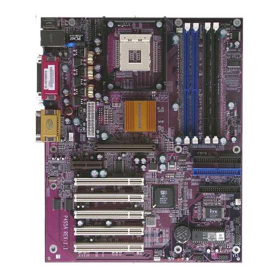
Page 12: Mainboard Components
Mainboard User’s Manual Mainboard Components Use the diagram below to identify the major components on the mainboard. Note: Any jumpers on your mainboard that do not appear in the illustration above are for testing only. -
Page 13: I/O Ports
2: Mainboard Installation I/O Ports The illustration below shows a side view of the built-in I/O ports on the mainboard. 1. Use the upper PS/2 port to connect a PS/2 pointing device. 2. Use the lower PS/2 port to connect a PS/2 keyboard. -
Page 14: Install A Cpu
Mainboard User’s Manual Install A CPU This mainboard has a Socket-478 which supports Intel Pentium 4 series processors. To ensure reliability, ensure that your processor has a heatsink/cooling fan assembly. Do neither try to install a Socket 370 processor nor a Socket423 in the Socket-478. -
Page 15: Installing Memory Modules
2: Mainboard Installation 5. Swing the locking lever down and hook it under the catch on the side of the socket. This secures the CPU in the socket. 6. All processors should be installed with a combination heatsink/ cooling fan, connect the cable from the fan to the CPU fan power connector CPU FAN1. - Page 16 Mainboard User’s Manual Installation Procedure The mainboard accommodates two memory modules. You must install at least one module in any of the three slots. Each module can be installed with up to 2GB system memory. Refer to the following to install the memory modules. 1.
-
Page 17: Setting Jumper Switches
2: Mainboard Installation Setting Jumper Switches Jumpers are sets of pins connected together with jumper caps. The jumper caps change the way the mainboard operates by changing the electronic circuits on the mainboard. If a jumper cap connects two pins, we say the pins are SHORT. If a jumper cap is removed from two pins, the pins are OPEN. - Page 18 Mainboard User’s Manual Install the mainboard in a case. Follow the instructions provided by the case manufacturer using the hardware and internal mounting points on the chassis. ATX_PW1 AUDIO1 SPK1 FAN2 Connect the power connector from the power supply to the ATX_PW1 connector on the mainboard.
-
Page 19: Optional Extension Brackets
2: Mainboard Installation Optional Extension Brackets For this mainboard, you can also obtain a USB module extension bracket for more USB ports. Install them by following the steps below. Note: All the ribbon cables used on the extension brackets have a red stripe on the Pin-1 side of the cable. -
Page 20: Install Other Devices
Mainboard User’s Manual Install Other Devices Install and connect other devices in the system as steps below. IDE1 IDE2 FDC1 Floppy Disk Drive The mainboard ships with a floppy disk drive cable that can support one or two drives. Drives can be 3.5” or 5.25” wide, with capacities of 360K, 720K, 1.2MB, 1.44MB, or 2.88MB. - Page 21 2: Mainboard Installation Internal Sound Connections If you have installed a CD-ROM drive or DVD-ROM drive, you can connect the drive audio cable to the onboard sound system. On the mainboard, locate the two 4-pin connectors CD_IN1 and CD_IN2. There are two kinds of connector because different brands of CD-ROM drive have different kinds of audio cable connectors.
-
Page 22: Expansion Slots
Mainboard User’s Manual Expansion Slots This mainboard has five 32-bit PCI slots, one AGP slot and one AMR slot. PC5 PC4 PC3 PC2 PC1 Follow the steps below to install a PCI/AGP/AMR expansion card. 1. Locate the AMR, AGP or PCI slots on the mainboard. 2. -
Page 23: Chapter 3: Bios Setup Utility
3: BIOS Setup Utility Chapter 3 BIOS Setup Utility Introduction The BIOS Setup Utility records settings and information about your computer such as the date and time, the kind of hardware installed, and various configuration settings. Your computer uses this information to initialize all the components when booting up and functions as the basis for coordination between system components. -
Page 24: Running The Setup Utility
Mainboard User’s Manual Running the Setup Utility Each time your computer starts, before the operating system loads, a message appears on the screen that prompts you to “Hit <DEL> if you want to run SETUP”. When you see this message, press the Delete key and the Main menu page of the Setup Utility appears on your monitor. -
Page 25: Standard Cmos Setup Page
3: BIOS Setup Utility Standard CMOS Setup Page Use this page to set basic information such as the date, the time, the IDE devices, and the diskette drives. If you press the F3 key, the system will automatically detect and configure the hard disks on the IDE channels. -
Page 26: Advanced Setup Page
Mainboard User’s Manual Advanced Setup Page Use this page to set more advanced information about your system. Take some care with this page. Making changes can affect the operation of your computer. AMIBIOS SETUP – ADVANCED SETUP (C) 2000 American Megatrends, Inc. All Rights Reserved Quick Boot Enabled Boot Device... - Page 27 3: BIOS Setup Utility Quick Boot If you enable this item, the system starts up more quickly be elimination some of the power on test routines. Boot Device Use these items to determine the device order the computer uses to look for an Boot Device operating system to load at start-up time.
- Page 28 Mainboard User’s Manual DRAM CAS# Latency This item determines the operation of DRAM memory CAS (column address strobe). It is recommended that you leave this item at the default value. The 3T setting requires faster memory that specifically supports this mode. Timing Setting Mode This item determines the timing setting mode of the memory.
-
Page 29: Power Management Setup Page
3: BIOS Setup Utility Power Management Setup Page This page sets some of the parameters for system power management operation. AMIBIOS SETUP – POWER MANAGEMENT SETUP (C) 2000 American Megatrends, Inc. All Rights Reserved ACPI Aware O/S Power Management Enabled Suspend Time out Disabled Hard Disk Time out... -
Page 30: Pci/Plug And Play Setup Page
Mainboard User’s Manual KeyBoard Power If you enable this item, you can turn the system on and off by pressing hot keys on the keyboard. You must enable the Keyboard Power On jumper and use an ATX power supply in order to use this feature. -
Page 31: Load Optimal Settings
3: BIOS Setup Utility Load Optimal Settings If you select this item and press Enter a dialog box appears. If you press Y, and then Enter, the Setup Utility loads a set of fail-safe default values. These default values are not very demanding and they should allow your system to function with most kinds of hardware and memory chips. -
Page 32: Features Setup Page
Mainboard User’s Manual Features Setup Page This page sets some of the parameters for peripheral devices connected to the system. AMIBIOS SETUP – FEATURES SETUP (C) 2000 American Megatrends, Inc. All Rights Reserved OnBoard FDC Enabled OnBoard Serial PortA 3F8h/COM1 OnBoard Serial PortB 2F8h/COM2 Serial Port2 Mode... - Page 33 3: BIOS Setup Utility Parallel Port Mode Use this item to set the parallel port mode. You can select SPP (Standard Parallel Port), ECP (Extended Capabilities Port), EPP (Enhanced Parallel Port), or ECP + EPP. Parallel Port IRQ Use this item to assign either IRQ 5 or 7 to the parallel port.
-
Page 34: Cpu Pnp Setup Page
Mainboard User’s Manual CPU PnP Setup Page This page lets you manually configure the mainboard for the CPU. The system will automatically detect the kind of CPU that you have installed and make the appropriate adjustments to the items on this page. AMIBIOS SETUP –... -
Page 35: Hardware Monitor Page
3: BIOS Setup Utility Hardware Monitor Page This page sets some of the parameters for the hardware monitoring function of this mainboard. AMIBIOS SETUP – HARDWARE MONITOR (C) 2000 American Megatrends, Inc. All Rights Reserved *** System Hardware *** Vcore 1.632V Vcc 2.5V/Vcc3.3V 2.496V... -
Page 36: Change Password
Mainboard User’s Manual Change Password If you highlight this item and press Enter, a dialog box appears which lets you enter a Supervisor password. You can enter no more than six letters or numbers. Press Enter after you have typed in the password. - Page 37 3: BIOS Setup Utility...
-
Page 38: Chapter 4: Software & Applications
4: Software & Applications Chapter 4 Software & Applications Introduction The support software CD-ROM attached to this mainboard package contains all necessary drivers and utility programs for properly running our products. You can find out a brief description of each software program and the location for your mainboard version as below. - Page 39 4: Software & Applications Note: The correct path name for each software driver is provided, where D: identifies the CD-ROM drive letter – modify if necessary. AGP Driver The AGP Drivers allows the system to properly manage the AGP slot on the mainboard. Find the driver here: ...
-
Page 40: Auto-Installing Under Windows 98
Mainboard User’s Manual BIOS Update Utility The BIOS Update utility allows you to update the BIOS file on the mainboard to a newer version. You can download the latest version of the BIOS setup available for your mainboard from the website. ... - Page 41 4: Software & Applications Installing Software with Auto Setup To install support software for the system board follow this procedure: 1. Click on the Setup button. The install program will load and display the following screen. Click the Next button. 2.
Need help?
Do you have a question about the M930LR and is the answer not in the manual?
Questions and answers