
Related Manuals for GRASS VALLEY INDIGO


Summary of Contents for GRASS VALLEY INDIGO
- Page 1 INDIGO AV Mixer User Manual Software Version 1.2.2 000 219 419 800 August 2007 / Revision 2...
- Page 2 And Conditions For Quality And Environmental Management Systems Certifications. Integral publication of this certificate is allowed. KEMA-Registered Quality, Inc. Accredited By: 4377 County Line Road ANAB Chalfont, PA 18914 INDIGO AV Mixer User Manual Ph: (215)997-4519 Fax: (215)997-3809 CRT 001 073004...
- Page 3 Grass Valley’s end-of-life product take back program assures proper disposal by use of Best Available Technolo- gy. This program accepts any Grass Valley branded equipment. Upon request, a Certificate of Recycling or a Certificate of Destruction, depending on the ultimate disposition of the product, can be sent to the requester.
- Page 4 Copyrights Copyright © Grass Valley Germany GmbH 2007. All Rights Reserved. Portions of this software are copyright © 2007, The FreeType Project (www.freetype.org). All rights reserved. Portions of this software are copyright © 1991-1998, The Independent JPEG Group, Thomas G. Lane. All rights reserved.
- Page 5 Tally/GPI/GPO ..........30 INDIGO AV Mixer User Manual...
- Page 6 Keyer Main Menu ..........83 INDIGO AV Mixer User Manual...
- Page 7 Mechanical Data ..........161 INDIGO AV Mixer User Manual...
- Page 8 ..............171 INDIGO AV Mixer User Manual...
-
Page 9: Section 1 — Safety Summary
— A personal injury hazard is immediately accessible as you read the marking. — A personal injury hazard exists but is not immediately acces- WARNING sible as you read the marking. — A hazard to property, product, and other equipment is present. CAUTION INDIGO AV Mixer User Manual... -
Page 10: Symbols On The Product
Indicates that static sensitive components are present which may be damaged by electrostatic discharge. Use anti-static procedures, equipment and surfaces during servicing. INDIGO AV Mixer User Manual... -
Page 11: Warnings
— Earth connection of product is essential before connecting power. Double pole neutral fusing — Disconnect mains power prior to servicing. Avoid mechanical hazards — Allow the fan to come to a stop before servicing. INDIGO AV Mixer User Manual... -
Page 12: Cautions
Dispose of used batteries according to the battery manufacturer’s instructions. The unit does not contain any user serviceable parts. If problems arise, please contact your local dealer. INDIGO AV Mixer User Manual... -
Page 13: Section 2 — Welcome
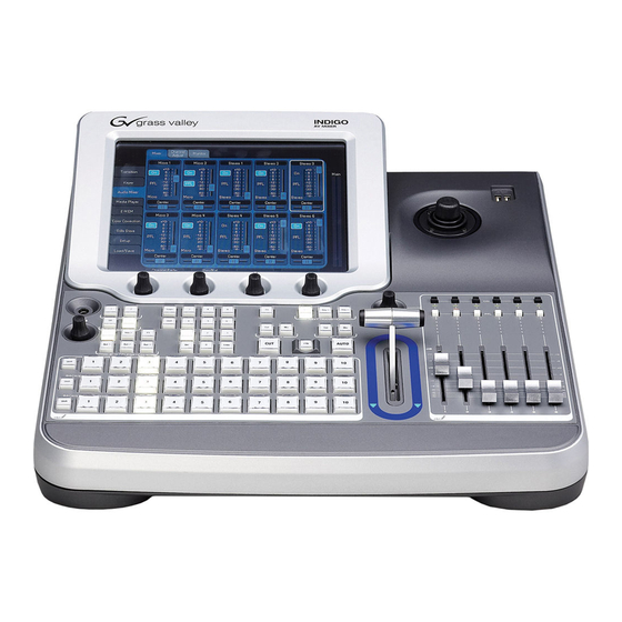
Section Welcome Welcome to the INDIGO AV Mixer. The INDIGO AV Mixer uniquely combines the advanced features of a video production switcher, a seamless switcher, and an audio mixer. Figure 1. The INDIGO AV Mixer INDIGO AV Mixer User Manual... -
Page 14: About This Manual
This User Manual also provides further details on how to operate the INDIGO AV Mixer in a network (Network Operation on page 147) and how to operate external devices (External Devices on page 149). The section Maintenance on page 151 explains how to clean the INDIGO AV Mixer, how to calibrate its operating elements, and how to update the software. -
Page 15: Related Documents
2.2 Related Documents You will find the complete User Manual and all Release Notes (as pub- lished so far) on the CD-ROM included in the INDIGO AV Mixer package. It provides you with comprehensive information about your INDIGO AV Mixer. - Page 16 Section 2 — Welcome INDIGO AV Mixer User Manual...
-
Page 17: Section 3 — Connections
Section Connections 3.1 Rear Panel Overview The following figure shows the rear panel of the INDIGO AV Mixer with its various connectors: Figure 2. Rear panel of the INDIGO AV Mixer Note All Sub-D connectors of the INDIGO AV Mixer use SAE inch threads, not ISO/DIN metric threads. -
Page 18: Electric Power Supply
Section 3 — Connections 3.2 Electric Power Supply 3.2.1 AC Power Cable Use the power cable to connect the power inlet of the INDIGO AV Mixer to the wall outlet. Note If required, ask your dealer for an appropriate power cable. -
Page 19: Video Connections
Via the optional HiRes board you can also make use of HD inputs and outputs as well as internal upscaled and downscaled signals. 3.4.1 Video Inputs Overview The following figure shows the video inputs of the INDIGO AV Mixer: Figure 5. Video input connections 3.4.2 Video Inputs The INDIGO AV Mixer provides various inputs for video, both analog and digital. -
Page 20: Video Outputs Overview
Using an appropriate adapter, analog VGA signals can also be input via the DVI-I connectors (see DVI-I to VGA on page 29). 3.4.3 Video Outputs Overview The following figure shows the video outputs of the INDIGO AV Mixer: Figure 6. Video output connections 3.4.4 Video Outputs The outputs listed below are sorted by sections (as labeled on the rear panel), in order to allow a quick and easy overview. - Page 21 Each downscaled output will replace one SDI input (11 = PGM, 12 = PVW). Note Using an appropriate adapter, also analog VGA signals can be output via the DVI-I connectors (see DVI-I to VGA on page 29). INDIGO AV Mixer User Manual...
-
Page 22: Analog Ref Connections
3.5 Analog Ref Connections The Analog Ref section provides two Black Burst outputs to sync external equipment, i.e. the INDIGO AV Mixer can be used as sync generator for the rest of the production system. It also provides a Black Burst input with a loop through connector to sync the INDIGO AV Mixer to an external reference signal. -
Page 23: Audio Connections
The INDIGO AV Mixer provides various analog and digital audio inputs and outputs. 3.6.1 Audio Inputs Overview The following figure shows the audio inputs of the INDIGO AV Mixer: Figure 8. Audio input connections Note All XLR connectors of the INDIGO AV Mixer correspond to IEC 61076-2-103. - Page 24 Note The LINE/MIC IN inputs can be amplified (see Mixer Submenu on page 97). Digital Audio Input The INDIGO AV Mixer provides the following connections for digital audio input: • 6 x AES/EBU (25-pin Sub-D connector, section DIGITAL AUDIO I/O)
-
Page 25: Audio Outputs Overview
Audio Connections 3.6.3 Audio Outputs Overview The following figure shows the audio outputs of the INDIGO AV Mixer: Figure 10. Audio output connections 3.6.4 Audio Output Types The INDIGO AV Mixer provides various analog and digital audio out- puts. Analog Audio Output... -
Page 26: Aes/Ebu Pin Out
Section 3 — Connections Digital Audio Output The INDIGO AV Mixer provides the following connections for digital audio output: • 2 x AES/EBU (25-pin connector, section DIGITAL AUDIO I/O) Note The first digital output provides the same audio signal as section ANALOG AUDIO MAIN OUT. - Page 27 OUT1+ OUT1- OUT1com OUT2+ OUT2- OUT2com Note The optional adapter INDIGO1-AUDIO_CABLE connects two XLR outputs and six XLR inputs with the 25pin AES/EBU connector of your INDIGO AV Mixer. The cable length is three meters. INDIGO AV Mixer User Manual...
-
Page 28: Monitors
Section 3 — Connections 3.7 Monitors The INDIGO AV Mixer provides program, preview, and auxiliary monitor outputs. 3.7.1 Program Monitors Program monitors are connected to the outputs in the PGM OUT section. You can connect up to five program monitors in parallel. -
Page 29: Usb Ports
USB Ports 3.8 USB Ports The INDIGO AV Mixer provides 3 USB ports: one on the rear panel and two on the top panel. Note The USB port on the rear panel is for future use and currently without func- tion. -
Page 30: Tally/Gpi/Gpo
The optional Tally Breakout Adapter provides an easy way to use the GPI / TALLY / GPO connector. 16 15 14 13 12 INDIGO GPI / TALLY / GPO BREAKOUT ADAPTER Figure 17. Tally Breakout Adapter INDIGO AV Mixer User Manual... - Page 31 36, 37 26, 27 5, 6 43, 44 38,39 12, 13 28, 29 45, 46 14, 15 30, 31 47, 48 16, 17 32, 33 49, 50 Figure 18. 50-pin Sub-D plug for GPI/GPO features INDIGO AV Mixer User Manual...
- Page 32 The other inputs are connected the same way: Figure 19. GPI interface The following figure shows how to connect GPO 1 of the GPO interface, as an example. The other inputs are connected the same way: Figure 20. GPO interface INDIGO AV Mixer User Manual...
-
Page 33: Section 4 — Initial Settings
Section Initial Settings If you switch on your INDIGO AV Mixer for the first time or use a new setup (i.e. you connected different or additional devices) you have to adjust the video and audio settings after first power-on. 4.1 Power-On Use the power switch on the rear side to switch on your INDIGO AV Mixer. -
Page 34: Audio Settings
Audio Control Subpanel (see Tutorials on page 67). By default, the faders are assigned according to the number of the audio signal input channel, for example, the signal from audio input 3 is routed to fader INDIGO AV Mixer User Manual... -
Page 35: Example Setup
4.4 Example Setup The following figure shows a possible setup: Figure 22. Connections for a big event setup See more examples and how to adjust the corresponding setups in the section Tutorials on page 67. INDIGO AV Mixer User Manual... - Page 36 Section 4 — Initial Settings INDIGO AV Mixer User Manual...
-
Page 37: Section 5 — Basic Operation
5.1 Overview of Control Features 5.1.1 Control Panel The INDIGO AV Mixer is operated by using the buttons, Digipots, lever controls, and the graphical menu on the Touch Screen. The buttons on the Control Panel are used during live operation for fast and real time control. -
Page 38: Touch Screen With Digipots
Section 5 — Basic Operation The following figure shows the Control Panel of the INDIGO AV Mixer with its various control features: INDIGO AV MIXER Learn Key 1 Key 2 USER NEXT TRANSITION NEXT TRANSITION USER MASTER VOLUME MASTER VOLUME... -
Page 39: Delegation Subpanel
DELEGATE section to determine which M/E is active: SD or HiRes. Bus Delegation The INDIGO AV Mixer M/Es include multiple sources as well as keyers and aux buses. To simplify use, the INDIGO AV Mixer panels provide alternate buses accessed by BUS DELEGATION buttons. -
Page 40: Crossbars For Bus And Source Selection
Section 5 — Basic Operation 5.1.4 Crossbars for Bus and Source Selection The INDIGO AV Mixer includes several inputs which can be used univer- sally for video or key signals. Figure 25. Crossbars for Bus and Source Selection Note Use the Shift buttons to access numbers 11 to 20 on the Bus, Background, and Background Preset Crossbars. -
Page 41: Main Transitions Subpanel With Transition Lever Arm
Background bus always remains the on-air bus. The Background bus selection remains the background source if this button is not selected as part of the next transition. INDIGO AV Mixer User Manual... - Page 42 The effects are selected and adjusted in the main TRANSITION menu. If the button is deactivated, the selected effects are ignored and Mix is used for transitions. See Transition Main Menu on page 77 for information on selecting effects. INDIGO AV Mixer User Manual...
-
Page 43: Numeric Input Subpanel
You can also adjust parameter values via the Numeric Input Subpanel. In this case, the Shift button outputs the decimal point (“.”) and the Learn button outputs the minus sign (“-”). Figure 28. Numeric Input Subpanel INDIGO AV Mixer User Manual... -
Page 44: Audio Control Subpanel
Figure 29. Audio Control Subpanel Mute/PFL Buttons PFL (Pre-Fader-Listening) Changes to PFL mode. This allows you to hear the audio signal on the headphones as it sounds before the fader. Turns the related audio channel on/off. INDIGO AV Mixer User Manual... -
Page 45: Joystick
• Yellow: -6 dB to -2 dB • Red: -2 dB to +10 dB Faders The faders adjust the input levels of the audio assigned to the INDIGO AV Mixer channels within the range of - to +10 dB. Use them to level the volumes of different audio sources. -
Page 46: Selecting Sources
(see KEYERS Keyer Main Menu on page 83). To save a Still (capture a video frame) from a currently displayed video, use the Stills Store menu (see Stills Store Main Menu on page 112). INDIGO AV Mixer User Manual... -
Page 47: Audio
(see Control Panel Submenu on page 135). You can assign an audio stream to a video source (see Audio Follow Video on page 64). See also Audio Settings on page 34 for information on configuring the audio settings. INDIGO AV Mixer User Manual... -
Page 48: Video Processing
5.3.1 Transitions, Effects, and Keying The INDIGO AV Mixer provides various ways to manipulate and mix video signals. The most common ways are described in the following. The first part of this section provides some theory and basic information about transitions and keying. - Page 49 Video Processing The INDIGO AV Mixer also provides cut transitions, where the elements involved in a mixed output can be changed instantaneously. Different buses can be included or excluded, causing changes in the resulting com- posite image. Background cut transitions on the M/E are first selected on the Background Preset bus to allow the upcoming picture to be previewed before it is cut “On Air”.
- Page 50 The art of setting up a good key is to use just enough Gain to suppress any imperfections in the incoming key sig- nals. Setting Gain too high can cause ragged key edges. The INDIGO AV Mixer provides two methods for adjusting the key control signal: • Clip and Gain •...
- Page 51 The INDIGO AV Mixer supports the following types of keys: • Luminance Key • Chroma Key •...
- Page 52 Background Video Key Hole Background Invert Clip Gain Completed Key Control Luminance Key Key Source (video only) Key Fill Figure 30. Luminance Key Clip and Gain controls for luminance keys offer wide adjustment ranges. INDIGO AV Mixer User Manual...
- Page 53 Chroma Key Primary Suppression Clip Gain Invert Key Control Completed Backing Colors Selected Chroma Key Chroma Key Secondary Suppression Chroma Key Fill Chroma Key Fill Backing Color Removed Backing Color Suppressed Figure 31. Chroma Key INDIGO AV Mixer User Manual...
- Page 54 When conditions are ideal, complete suppression of the backing color is possible and the hole cut in the background will match the suppressed foreground, permitting these two signals to be added successfully. INDIGO AV Mixer User Manual...
-
Page 55: Making A Background Transition
For HiRes, only Wipes and Mix are available. 6. Press the button. AUTO See Duration Submenu on page 82 if you want to modify the duration of the Auto transition. – or – Move the to the opposite position. Transition Lever Arm INDIGO AV Mixer User Manual... -
Page 56: Making A Title
: Characters from title generator Fill : “Alpha channel” from title generator 7. Press the Adjust button. 8. Press the button. Auto 9. Select the mode ( Clip Gain Cleanup Density If necessary, adjust the settings. INDIGO AV Mixer User Manual... - Page 57 – or – Press the button. AUTO See Duration Submenu on page 82 if you want to modify the duration of the Auto transition. – or – Move the Transition Lever Arm to the opposite position. INDIGO AV Mixer User Manual...
-
Page 58: Making A Chroma Key
9. If required, adjust the Chroma and Selectivity values manually. 10. Press the button. Cut [KEY 1] Mix [KEY 1] – or – Press the AUTO button. – or – Move the to the opposite position. Transition Lever Arm INDIGO AV Mixer User Manual... -
Page 59: Making An Effect Transition
– or – Press the AUTO button. See Duration Submenu on page 82 if you want to modify the duration of the Auto transition. – or – Move the to the opposite position. Transition Lever Arm INDIGO AV Mixer User Manual... -
Page 60: Making A Pip (Picture In Picture) In Sd Mode
9. Adjust Top Corner, Bottom Corner, and 2D Size as desired to position and resize the picture. 10. Press the Cut [KEY 1] Mix [KEY 1] button. – or – Press the button. AUTO – or – Move the Transition Lever Arm to the opposite position. INDIGO AV Mixer User Manual... -
Page 61: Making A Pip (Picture In Picture) In Hr Mode
This setup is not possible using only regular Keyer PiPs (like in Making a PiP (Picture in Picture) in HR Mode on page 61), because four images are visible, but there are only three HR inputs – two full featured and one internal. INDIGO AV Mixer User Manual... - Page 62 Select IN01 HR or IN02 HR. Do not select a Still! 4. Press Transform 5. Make sure the Enable button is activated. 6. Make sure the PiP Enable button is activated. 7. Select Hi-Res [DELEGATE] 8. Select Key 1 [BUS DELEGATE] INDIGO AV Mixer User Manual...
- Page 63 Changing the size or the Internal SD Alignment may help. Note The HR sync signal must always be valid. If an HR input signal is or becomes invalid (i.e., no or no valid sync), the PiP will blink for approx. 15 seconds. INDIGO AV Mixer User Manual...
-
Page 64: Audio Processing
Activated (enabled) video and audio sources are displayed as green entries within the lists. 5.4.1 Mic Inputs The INDIGO AV Mixer includes four LINE/MIC IN mono inputs to feed in microphones or line levels. If required, switch on phantom power (+48 V DC) for microphones. This can be activated separately for inputs 1/2 and 3/4. -
Page 65: Mic Inputs
The INDIGO AV Mixer provides a 4-band equalizer for each channel, i.e. you can adjust four different frequencies simultaneously: Low, Mid 1, Mid 2, and High. - Page 66 Accessing channel settings If you press and hold a channel’s button for approximately two sec- onds, the Touch Screen will display the CHANNEL ADJUST submenu (see Channel Adjust Submenu on page 99). INDIGO AV Mixer User Manual...
-
Page 67: Section 6 — Tutorials
This chapter contains practical tutorials to show you how to work with the INDIGO AV Mixer, how to choose the appropriate devices, connect them to your INDIGO AV Mixer, adjust the settings for all video and audio channels, and compose the output signal. -
Page 68: Tutorial 1—Small Presentation
Section 6 — Tutorials 6.1 Tutorial 1—Small Presentation Use the INDIGO AV Mixer for your company presentations or other small events. Only a few devices and settings are necessary to create an impressive pre- sentation. Note This example makes use of the optional HiRes board’s DVI inputs and out- puts. -
Page 69: Connections
DVI-I MAIN of the COMPUTER VIDEO OUT section (HiRes board) • (7) Amplifier with speakers; connected to ANALOG MAIN OUT via • (8) Headphones; connected to the phones jack on the top panel The devices are connected to your INDIGO AV Mixer as follows: DVI-I MAIN S-Video 1... -
Page 70: Result
6.1.3 Result This is what your presentation could look like: Figure 35. Your presentation from the audience’s view The INDIGO AV Mixer produces a presentation view mixed by three sig- nals: • The background is a PPT presentation from the laptop. -
Page 71: How To Set Up A Small Presentation
Adjust volume and pan. 7. Select CHANNEL ADJUST submenu. a. Make sure the button is activated. Equalizer On b. Adjust the equalizer settings to your needs. c. If required, adjust the Mic Gain. d. Activate Low Cut INDIGO AV Mixer User Manual... - Page 72 Select IN01 SD Still or newly named Still (the logo) as Fill and Key. e. Press Adjust Press Auto g. If required, adjust Chroma and Selectivity manually. h. Press Transform Make sure the button is activated. Enable Adjust Top Corner, Bottom Corner, and 2D Size as desired. INDIGO AV Mixer User Manual...
-
Page 73: Section 7 — Menus
Section Menus 7.1 General Handling of the Menus This section shows you how to work with the menus of your INDIGO AV Mixer in general and provides you with a quick reference for looking up information regarding the single menus. -
Page 74: Menu Navigation And Organization
In the menus, use the Parameter Navigation Area in the upper part to select the parameter you want to modify. In the Parameter Edit Area in the middle and by using the Digipots, you can then adjust the parameter values. INDIGO AV Mixer User Manual... -
Page 75: Virtual Numeric Keypad And Keyboard
Digipot. Type in the new parameter value and press In a similar fashion, you can use a Virtual Keyboard to edit the name of a stored file or to rename an E-MEM. Figure 38. Virtual Keyboard INDIGO AV Mixer User Manual... -
Page 76: Onscreen Preview
SD outputs directly on the Touch Screen. Thus, you can check the signal output or adjust a chroma key without having to use an external monitor. Figure 39. Onscreen Preview window Note There is no onscreen preview available for HiRes PGM or PVW. INDIGO AV Mixer User Manual... -
Page 77: Auto Menu Delegation
Key 1 and Key 2 for both SD and HR in the SD/HR Effects Submenu (see page 78). • Define the duration of the selected effect in the Duration Submenu (see page 82). See Video Processing on page 48 for more information on transitions and effects. INDIGO AV Mixer User Manual... -
Page 78: Sd/Hr Effects Submenu
SD BGND 2. In the Parameter Edit Area, select one of the Categories and the effect Pattern. Depending on the selected pattern, additional parameter areas are dis- played which allow you to change specific parameters. INDIGO AV Mixer User Manual... - Page 79 You can independently define transitions for the SD background and the two SD keyers. SD BGD For the SD background, the following effect categories are available: • Wipe • Mix • 3D • Page Roll • Page Turn • Slide • Squeeze • Door INDIGO AV Mixer User Manual...
- Page 80 32 Multi 32 Multi Vertex L 64 Multi 64 Multi Rect 128 Multi 128 Multi Circle Inf Multi Star 2 Out Clock Inf Out Clock4 Angle Matrix 1 Matrix 2 Rings Slit4 H Slit4 V INDIGO AV Mixer User Manual...
- Page 81 Overview of HR Effect Patterns The following patterns are available for Wipe: • Left • Top • Cross • Rect The following patterns are available for Mix: • White Mix • Black Mix • Matte Mix INDIGO AV Mixer User Manual...
-
Page 82: Duration Submenu
Figure 41. Transition Duration submenu Use the Digipots to adjust the duration, or enter the value with the Virtual Numeric Keypad. The duration is displayed in seconds and frames, and ranges from 0 to 59 seconds. INDIGO AV Mixer User Manual... -
Page 83: Keyer Main Menu
• Modifying the key size and position (see page 93). Type Select the key type: • Chroma • Luma • (Picture in Picture) Depending on the key type, different parameters will be displayed in the Adjust and the Border section. INDIGO AV Mixer User Manual... - Page 84 You can also select the sources via the crossbars: • Fill Press the corresponding button on the Bus Crossbar. • Key Press and hold the desired BUS DELEGATION button (for example, Key 1 and select the corresponding source from the Bus Crossbar. INDIGO AV Mixer User Manual...
- Page 85 See also Key Control Signal Adjustment on page 50 for detailed information. Figure 43. Adjusting the Keyer parameters Auto The INDIGO AV Mixer automatically sets the key signal parameters to suitable values (automatic chromakey computation). Cursor This button is only available if you selected as the key type.
- Page 86 This section is displayed only if you selected as the key type. Luma Select the fade mode for the Luma key: • for additive fading Add. • X-Fade for crossfading Invert Inverts the key signal. INDIGO AV Mixer User Manual...
- Page 87 If you selected as the key type, you get two additional display Chroma fields: • Chroma to modify Hue, Luminance and Saturation • Selectivity to modify Color Offset (C), Left (L) and Right (R) Selec- tivity INDIGO AV Mixer User Manual...
- Page 88 Chroma Luma lowing parameters: Figure 44. Modifying the key border Chroma or Luma as the key type Type Note This section is not available for HR keys. HR keys only have the type Border. INDIGO AV Mixer User Manual...
- Page 89 Crop and Border parameters. Use the Crop functions to “trim” the edges of a key. The picture edge will be replaced with the background video. Figure 45. Modifying the key border for PiP as the key type INDIGO AV Mixer User Manual...
- Page 90 Allows you to modify the values for the left ( ), right ( ), top ( ) or bottom ( ) edge. • Border Color Allows you to modify Hue, Luminance and Saturation in the param- eter display field. INDIGO AV Mixer User Manual...
- Page 91 This functionality is not available for HR keys. Press to display the mask parameters and patterns. Enable Figure 46. Modifying the mask and pattern parameters Crop Automatically truncates the width of an analog signal, so blanking does not extend into the image. INDIGO AV Mixer User Manual...
- Page 92 Inverts the mask. The parameter display fields in the lower part of the Parameter Edit Area allow you to adjust the size and appearance of the mask. Preview Shows the modified signal on the Preview output. INDIGO AV Mixer User Manual...
- Page 93 For every SD keyer type, you can modify the following properties: • Top Corner • Bottom Corner • 2D Size • 3D Rotation • 3D Position Figure 47. Modifying the key size and position for SD keys INDIGO AV Mixer User Manual...
- Page 94 • Use the parameters in the 3D Rotation display field to rotate the center of the key around the x-, y- or z-axis. • Use the parameters in the 3D Position display field to move the center of the key along the x-, y- or z-axis. INDIGO AV Mixer User Manual...
- Page 95 Note Alternatively, you can use the Joystick to adjust position and size. • Use the parameters in the 2D Position display field to move the center of the key along the x- and y-axis. INDIGO AV Mixer User Manual...
- Page 96 PiP function: • PiP Size 2D • PiP Position 2D Find detailed information on how to use this function for “PiP in PiP” in Making a PiP within a PiP in HR Mode on page 61. INDIGO AV Mixer User Manual...
-
Page 97: Audio Mixer Main Menu
The number and type (Stereo or Micro) of the channels displayed in this submenu depend on the selection in the main Operation Mode SETUP menu (see Audio Submenu on page 129). Figure 49. Mixer submenu INDIGO AV Mixer User Manual... - Page 98 Indicates the Equalizer is turned on for this channel. You can turn the Equalizer on/off for the selected channel in the CHANNEL ADJUST submenu (page 99). See Adjusting Audio on page 65 for further information. INDIGO AV Mixer User Manual...
-
Page 99: Channel Adjust Submenu
The frequency of each of the four bands can be set individually. You may also set the Q factor (quality) – i.e., the width of the filter – for the Mid 1 and Mid 2 bands. INDIGO AV Mixer User Manual... - Page 100 Channel Gain (Stereo Input) or Pre Gain (Mic Input) This slider lets you adjust the input level to get a good level for mixing. INDIGO AV Mixer User Manual...
-
Page 101: Monitor Submenu
Main Out, Sub-Out and the headphones. Figure 51. Monitor submenu Mute Mutes the corresponding output. This applies to the Main Out, Sub Out, Add Sub to Main, and Phones Out sections. INDIGO AV Mixer User Manual... - Page 102 Allows you to set the power of the phone amp to adjust it to your studio headphone: is 100%, is 50% and is 25%. High Use the faders of the Phones Out section to gain up the signal, if necessary. INDIGO AV Mixer User Manual...
-
Page 103: Media Player Main Menu
Figure 52. Remote Control submenu Loop Sets the loop status of the clip. If active, the defined section (IN/OUT) of the clip is repeated endlessly (for example, on a Turbo iDDR). INDIGO AV Mixer User Manual... - Page 104 While a clip is playing, you can also see the current position in the upper row (TC, time code). Use the player control buttons in the lower right corner to play, pause, rewind and fast forward the clip. INDIGO AV Mixer User Manual...
-
Page 105: Favorites Submenu
Moves the selected clip to another destination on this screen. By using this button, you can change the order of your favorite clips. To move a clip to another position: • Select the clip. • Press Move To • Select the desired position. INDIGO AV Mixer User Manual... - Page 106 Section 7 — Menus Remove from List Removes the selected clip from the list. Load Clip Loads the selected clip. Use the player control buttons on the bottom to play, pause and rewind the clip. INDIGO AV Mixer User Manual...
-
Page 107: E-Mem Main Menu
E-MEMs. An E-MEM can be E-MEM a stored preset state of the INDIGO AV Mixer, or even a sequence of suc- cessive (interpolated) states. The state defines parameter settings for video, audio, effects and transitions. - Page 108 E-MEM. Rename... To recall an E-MEM, select it and press Recall In addition, you can use the Numeric Input Subpanel to store and recall E-MEMs (see Numeric Input Subpanel on page 43). INDIGO AV Mixer User Manual...
-
Page 109: Correction/Mattes Main Menu
Switches the color correction and the display of the parameters for the selected source on or off. A green entry in the Sources list indicates that the color correction is active for the corresponding source. INDIGO AV Mixer User Manual... - Page 110 3. Select the desired color component (Red, Green, or Blue) by touching the corresponding area on the screen. 4. Use the Digipots to modify the parameters. 5. If required, repeat step 4 for other color components. 6. If required, also adjust Luma and Chroma. INDIGO AV Mixer User Manual...
-
Page 111: Mattes Submenu
SD and four HR color mattes. Figure 56. Mattes submenu Default Sets all parameters to the predefined default values. Note Mattes can be assigned to Control Panel buttons. See Button Assignment on page 136 for more details. INDIGO AV Mixer User Manual... -
Page 112: Stills Store Main Menu
STILL SD and STILL HR submenu, only STILL SD submenu, or only STILL HR submenu. The functionality of SD and HR submenu is nearly identical. Sources Select the video input source to take the Still from. INDIGO AV Mixer User Manual... - Page 113 This dialog also allows you to create new directories and delete or rename Stills. Note For SD, when saving color bars in PNG format, the color Magenta will be changed, because it exceeds the RGB color space. INDIGO AV Mixer User Manual...
- Page 114 The currently selected directory is shown in the Current Directory dis- play. 4. If desired, press Current Filename to change the name. 5. Select JPEG as file format. 6. Press to save the still. Save INDIGO AV Mixer User Manual...
- Page 115 4. Select the desired Still from the list of image files. The currently selected filename is shown in the Current Filename dis- play. 5. Press to open the file. Load The Still is loaded into the selected memory cell and a thumbnail is shown. INDIGO AV Mixer User Manual...
-
Page 116: Setup Main Menu
Mixer is connected to a network, for example, to remotely control a Turbo iDDR. Note In order to be able to remotely control a Turbo iDDR via network, the INDIGO AV Mixer and the Turbo iDDR must use the same address range. You can set up the following ID parameters: •... - Page 117 IP parameters. Edit... No Network Select this button if the INDIGO AV Mixer is not connected to a network. Static IP Select this button if you want to assign static IP parameters. Touch the...
- Page 118 Sub Net Mask. Diagnosis This display provides you with information on: • The fan status and the system’s temperature • The version of the mainframe and its panel Figure 59. Overview of the system status INDIGO AV Mixer User Manual...
- Page 119 Setup Main Menu See Troubleshooting on page 159 for information on how to handle the error messages. Reset Press Reset All to reset the complete system to default settings. INDIGO AV Mixer User Manual...
-
Page 120: Video Submenu
Downscaled • (for sources 11 and 12) DV IEEE 1394 • VGA, DVI, SDI HD (for sources 13 and 14 [HR]) • (for sources 13 to 15 [HR]) Internal SD Figure 60. Video input settings INDIGO AV Mixer User Manual... - Page 121 Internal SD Inputs 13 to 15 can be set to show internal (upscaled) SD signals. The fol- lowing internal sources can be selected: • SD PGM • SD PVW • SD AUX1 • SD AUX2 INDIGO AV Mixer User Manual...
- Page 122 For background signals (program and preset), the “output window” is the screen of the PGM or PVW monitor. For HR keyers in PiP mode, it is the size that you defined in the Transform section (see HR Keys on page 95). INDIGO AV Mixer User Manual...
- Page 123 If necessary, repeat steps b and c. • Green message (“Input is in range for framesync bypass”) If this message is shown, bypass will work properly and you can acti- vate the button. Bypass Framesync INDIGO AV Mixer User Manual...
- Page 124 For this command to work, the clip must have been saved to Favorites from the same source that you are now taking to air. To adjust an offset of the external media player, set an appropriate Preroll time. INDIGO AV Mixer User Manual...
- Page 125 135). • SD-Flat In the SD mode, only SD ME is available. SD inputs 9 and 10 are replaced by HR inputs 1 and 2. No HR inputs can be configured for internal SD sources. INDIGO AV Mixer User Manual...
- Page 126 The HR program and preview signals – available in SD output format on SD AUX 1 and AUX 2 – can be used for recording. Video SD Output Settings In this section, you can select the format of the SD video output. Figure 63. Video SD output settings INDIGO AV Mixer User Manual...
- Page 127 The NTSC Pedestal setting always affects both inputs and outputs. Indepen- dent settings are not possible. Ext. Lock Enable Allows you to lock the INDIGO AV Mixer to an external reference signal. The external reference signal must match the selected video standard ( NTSC...
- Page 128 Select the graphic standard of the video output. Note Changing the graphic standard may take up to 30 seconds. To change the graphic standard: 1. Select the desired setting from the Graphic Standard list. 2. Click Apply INDIGO AV Mixer User Manual...
-
Page 129: Audio Submenu
Mixer Inputs. The following audio inputs are available: • RCA • TRS (TRS 1/4’’ Phone) • XLR • AES • SDI • SineGen (sine wave generator) Figure 65. Audio input assignment INDIGO AV Mixer User Manual... - Page 130 ) and the channel pair Pair 1/2 ) where the audio is to be taken from. SineGen The sine wave generator can be used for testing and analyzing purposes. It generates a frequency of 440 Hz. INDIGO AV Mixer User Manual...
-
Page 131: Audio Output
You can also set the XLR Out Level (i.e., the output gain) to High Sub Out Provides the same options as Main Out. In addition, you can set a Delay in milliseconds (independently for left and right channel), for example, to balance wide distances between the speakers. INDIGO AV Mixer User Manual... -
Page 132: Operation Mode
LINE/MIC IN inputs. Note When assigning an XLR connector to a Mic Input, the corresponding Gain parameter in Audio Mixer changes from Channel Gain to Mic Gain, indicating the individually used pre-amplifier circuits. INDIGO AV Mixer User Manual... -
Page 133: Audio Follow Video
AVF Enable. The Video Sources list is displayed. 2. Select the video signal from the Video Sources list. You can also select Stills from this list. 3. Press Audio Sources The Audio Sources list is displayed. INDIGO AV Mixer User Manual... -
Page 134: Input Delay
6. If desired, you can change the volume level (in dB) for “on air” (right fader) and “off air” (left fader). Input Delay In this section, you can change the delay settings for the audio inputs. Figure 68. Input Delay INDIGO AV Mixer User Manual... -
Page 135: Control Panel Submenu
• Touch Screen • Transition Lever Arm (T-Bar) Additionally, you can also enter the calibration mode of the Touch Screen by pressing all four Digipots simultaneously. For detailed descriptions on the calibrations, see Calibrations on page 155. INDIGO AV Mixer User Manual... - Page 136 1. Select the desired button from the Buttons list. ([S] stands for the button on the left side of the crossbar.) Shift 2. Select the video signal’s source from the Sources list. 3. Press Assign Default Resets the assignment of the selected button. INDIGO AV Mixer User Manual...
-
Page 137: Fader Assignment
1. Select the desired fader from the Fader list. 2. Select the audio signal’s source from the Sources list. The entries in this list depend on your selection of the operation mode in the submenu. AUDIO 3. Press Assign INDIGO AV Mixer User Manual... -
Page 138: Gpio Submenu
Use the buttons in the Parameter Navigation Area on the top to access the following sections: Here you define actions to be triggered for up to eight GPIs. See also Tally/ GPI/GPO on page 30. Figure 71. Configuring the GPI INDIGO AV Mixer User Manual... - Page 139 Select the trigger type from the Trigger list. Depending on the selected action, this can be Closed/Opened or Rising/Falling/Both. EMEM/Channel/Transition This shows the “destination” of the action. Depending on the selected action, you can select an E-MEM, a channel or a transition from the list. INDIGO AV Mixer User Manual...
- Page 140 (if both are selected). 4. Set the desired GPO status from the Active list. Note If you select Fixed from the Sources list, you can set a GPO to permanent Open or Closed status. INDIGO AV Mixer User Manual...
- Page 141 E-MEM (if is active in the E-MEM menu, see E-MEM Main Menu on page 107). is highlighted, the contact of the corresponding GPO is set to the Active Active state (here: Closed). INDIGO AV Mixer User Manual...
- Page 142 The pulse length will also be recorded in the E-MEM, but not the polarity. Active is highlighted, the contact of the corresponding GPO is set to the Active state (here: Closed). INDIGO AV Mixer User Manual...
-
Page 143: External Devices Submenu
7.9.6 External Devices Submenu Use this submenu to define external media players and to set up the INDIGO AV Mixer for remote control via external devices. Media Players In this section you define up to eight external devices (for example, Turbo... - Page 144 PLAYER Edit In this section you define how your INDIGO AV Mixer can be remotely controlled by an external editing system. Figure 76. Configuring the Indigo for remote control To set up the INDIGO AV Mixer for remote control: 1.
- Page 145 Mapping GVG 100 • Mapping GVG 200 provides 36 background wipes. • provides all effects of the menu. Mapping Indigo TRANSITION Note If you select <none> the currently selected effect from the TRANSITION menu will be used. INDIGO AV Mixer User Manual...
-
Page 146: Load/Save Main Menu
LOAD/SAVE (including keyer settings, input/output routings, E-MEMs etc.) of your INDIGO AV Mixer using an external USB device, for example, a USB stick. Thus, different users can quickly and easily use their individual set- tings by loading a setup within seconds. -
Page 147: Section 8 — Network Operation
8.1 Purpose The main purpose of network operation is to connect the INDIGO AV Mixer to a network, for tasks such as remotely controlling a Turbo iDDR that also belongs to this network. Connect the INDIGO AV Mixer to the network via Ethernet. - Page 148 Section 8 — Network Operation Note In oder to be able to remotely control a Turbo iDDR via network, the INDIGO AV Mixer and the Turbo iDDR must use the same address range, for example: IP Address Sub Net Mask INDIGO AV Mixer 192.168.0.100...
-
Page 149: Section 9 — External Devices
9.1 Players and Recorders To remotely control players and recorders via the INDIGO AV Mixer, the following protocols are supported: • GVG-100/200: Supports transport functions only. GVG-100 supports 1-M/E mixers, GVG-200 also supports 2-M/E mixers. - Page 150 Section 9 — External Devices GVG-200 This is the same as GVG-100, but allows control of 2-M/E mixers, i.e. the two M/Es of the INDIGO AV Mixer can be controlled separately. INDIGO AV Mixer User Manual...
-
Page 151: Section 10 — Maintenance
• PC with CF card reader • CF card with at least 128 MB capacity, formatted with FAT file system Note The CF card of your INDIGO AV Mixer will do, but you may want to keep the old software on it. Procedure To update the software: 1. - Page 152 5. Insert the CF card (or a new, FAT formatted one) into the CF card reader of the PC. 6. On the PC, open the downloaded self-extracting .EXE file. It will automatically run the software installation tool Indigo CD. 7. Select Install new software on Indigo device to copy the new software onto the CF card.
- Page 153 CF Card / Software Update 10. With your INDIGO AV Mixer still turned off, insert the CF card containing the new software into the slot. CAUTION Do not insert the CF card below the mainboard. 11. Close the slot. 12. Turn on the INDIGO AV Mixer.
-
Page 154: Cleaning
The battery type must be CR 2032. 5. Close the cover and screw in the screws. 6. Switch on the INDIGO AV Mixer and set the correct system time. Note The menu to set the system time will be added in the next software release. -
Page 155: Calibrations
Calibrations 10.4 Calibrations When you switch on your INDIGO AV Mixer for the first time or if you encounter problems with the operation devices, calibrate the system as fol- lows. 10.4.1 Touch Screen To calibrate the Touch Screen: 1. Press all four Digipots at once to enter calibration mode. -
Page 156: Transition Lever Arm (T-Bar)
5. Move the Transition Lever Arm up as indicated by the calibration procedure. 6. Press the button. 7. Move the Transition Lever Arm down as indicated by the calibration procedure. 8. Press the button. 9. Press again to store the calibration. INDIGO AV Mixer User Manual... -
Page 157: Faders
Joystick 5. Move the Joystick to the upper left position as indicated by the calibration procedure. 6. Press the button. 7. Move the Joystick to the lower right position as indicated by the calibration procedure. INDIGO AV Mixer User Manual... - Page 158 9. Twist the Joystick to the left as indicated by the calibration procedure. 10. Press the button. 11. Twist the Joystick to the right as indicated by the calibration procedure. 12. Press the button. 13. Press again to store the calibration. INDIGO AV Mixer User Manual...
-
Page 159: Section 11 — Troubleshooting
The INDIGO is off Switch on the device There is no CF card with the INDIGO soft- Insert a CF card with the required INDIGO ware in the drive software The Transition Lever Arm The Transition Lever Arm is not calibrated Go to Setup >... - Page 160 The speakers/amplifier are/is not con- Check the connection of the speakers and the audio meter moves nected properly the amplifier Sound balance is inverted The cables are mixed up Check the audio output connections INDIGO AV Mixer User Manual...
-
Page 161: Section 12 — Technical Specifications
E2 (according to EN55103-1, -2) environment 12.3 Mechanical Data Width 444 mm (17.5 inch) Depth 469 mm (18.5 inch) Height 57 … 211 mm (2.3 – 8.3 inch) Weight INDIGO1-SD 9 kg (19.8 lbs) INDIGO1-HR 9.5 kg (20.9 lbs) INDIGO AV Mixer User Manual... - Page 162 Section 12 — Technical Specifications INDIGO AV Mixer User Manual...
- Page 163 Blue and green which a key may be inserted. are the chroma key colors most frequently used. Backing Color The color in a chroma key scene that will be replaced with another video signal. INDIGO AV Mixer User Manual...
- Page 164 It is commonly used for another. Switching circuitry allows cuts only high definition (HD) signals, for example, during the vertical interval of the video sig- from PC to TFT monitor. nal to prevent disruption of the picture. INDIGO AV Mixer User Manual...
- Page 165 Also the amplification (boost) of an audio signal, esp. useful with mic inputs. Straight-line slider for the audio level con- trol. GP (General Purpose Interface) An interface that allows limited remote con- trol of some of a device’s functions. INDIGO AV Mixer User Manual...
- Page 166 Key Mask A key mode which allows use of a wipe pat- tern generator to prevent some undesirable portions of the key cut signal from cutting holes in the background video. INDIGO AV Mixer User Manual...
- Page 167 A high pass filter that removes low frequen- which one signal is faded down as the other cies from an audio signal. Useful for speakers is faded up. to remove low-level noise and to make speech clearer. INDIGO AV Mixer User Manual...
- Page 168 A type of clean feed where different keys can A picture element. A pixel is a digital sample be selected for inclusion or exclusion from of the luminance and color values of a pic- the clean feed. ture at a single point. INDIGO AV Mixer User Manual...
- Page 169 Passing video data bits in serial form (one bit Store (Learn) after another), along a single wire. To save a panel setup using E-MEM. Standard Definition serial digital video (SMPTE 259M) operates at 270 MBits/sec (2 x 13.5 MHz x 10 bits). INDIGO AV Mixer User Manual...
- Page 170 Transition A change from one picture to another. Cut, mix, and wipe are transitions. INDIGO AV Mixer User Manual...
- Page 171 Control Panel Control Panel Submenu Correction/Mattes Main Menu Background Crossbar Crop function Background Preset Crossbar Crossbars Background transition Battery Black Burst input/output connections Border Bus Crossbar De-embedded Audio Bus Delegation Delegation Subpanel Button assignment DHCP Diagnosis INDIGO AV Mixer User Manual...
- Page 172 LED Peak-Meters Linear Editors (protocols) GPI configuration Linking/Unlinking the faders GPI/Tally/GPO connector Load/Save Main Menu GPIO Submenu Loading a clip Loading a Still configuration Low Cut eMEM Level eMEM Pulse Luminance Key Ground Screw GVG-100 GVG-200 INDIGO AV Mixer User Manual...
- Page 173 Safety terms in the manual Safety terms on the product Saving a Still Network connection SD/HR Effects Submenu Network settings Selecting an effect Numeric Input Subpanel Selecting audio sources Selecting the current background picture Selecting the key type INDIGO AV Mixer User Manual...
- Page 174 Submenu tab cards Supress FGD Symbols on the product System reset System Submenu Tally Breakout Adapter Technical data Touch screen Touch Screen calibration Transition Lever Arm Transition Lever Arm calibration Transition Main Menu Transitions Troubleshooting USB ports INDIGO AV Mixer User Manual...
Need help?
Do you have a question about the INDIGO and is the answer not in the manual?
Questions and answers