
Subscribe to Our Youtube Channel
Related Manuals for Eaton 5P 1500 RT


Summary of Contents for Eaton 5P 1500 RT
- Page 1 5P 1500 RT 5P 2200 RT 5P 2200 5P 3000 RT 5P 3000 Installation and user manual Copyright © 2012 EATON All rights reserved. Service and support: Call your local service representative 614-03898-00_EN...
- Page 2 Page 2 614-03898-00_EN...
-
Page 3: Important Safety Instructions
IMPORTANT SAFETY INSTRUCTIONS SAVE THESE INSTRUCTIONS. This manual contains important instructions that should be followed during installation and maintenance of the UPS and batteries. The 5P models that are covered in this manual are intended for installation in an environment within 0 to 40°C, free of conductive contaminant. -
Page 4: Safety Of Persons
During the replacement of the Battery Module, it is imperative to use the same type and number of element as the original Battery Module provided with the UPS to maintain an identical level of performance and safety. In case of doubt, don’t hesitate to contact your EATON representative. Page 4... -
Page 5: Table Of Contents
Contents 1. Introduction ..................6 1.1 Environmental protection....................6 2. Presentation ..................7 2.1 Standard installations .......................7 2.2 Rear Panels ........................8 2.3 Control panel ........................9 2.4 LCD description ......................10 2.5 Display functions ......................11 2.6 User settings ......................... 11 3. Installation ..................13 3.1 Unpacking and contents check .................. -
Page 6: Introduction
Before installing your 5P , please read the booklet presenting the safety instructions. Then follow the indications in this manual. To discover the entire range of EATON products and the options available for the 5P range, we invite you to visit our web site at www.eaton.com/powerquality or contact your EATON representative. -
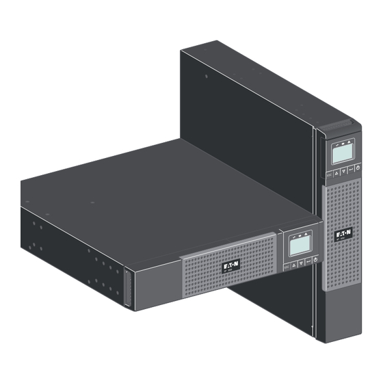
Page 7: Presentation
Rack installation Description Weights Dimensions (inch/mm) (lb/kg) D x W x H 5P 1500 RT 58.60 / 26.60 20.6 x 17.4 x 3.4 / 522 x 441.2 x 86.2 5P 2200 RT 60.20 / 27 .30 5P 2200 5P 3000 RT 81.10 / 36.80... -
Page 8: Rear Panels
2. Presentation 2.2 Rear panels 5P 1500 USB communication port RS232 communication port Not used, connector for automatic recognition of an additional battery module Slot for optional communication card Connector for ROO (remote ON/OFF) or RPO (Remote Power OFF) control 30A outlet (L5-30R) for connection of equipment (for 5P 3000 only) Group 1: 2 programmable outlets for... -
Page 9: Control Panel
2. Presentation 2.3 Control panel The UPS has a five-button graphical LCD. It provides useful information about the UPS itself, load status, events, measurements and settings. Power On On battery Alarm Indicator (green) Indicator (yellow) Indicator (red) Normal mode 100% 100% 2.7kW 17min... -
Page 10: Lcd Description
2. Presentation 2.4 LCD description After 5 minutes of inactivity, the LCD displays the screen saver. The LCD backlight automatically dims after 10 minutes of inactivity. Press any button to restore the screen. Operation status Normal mode 100% 100% Load/equipment status 2.7kW 17min Battery status... -
Page 11: Display Functions
2. Presentation 2.5 Display functions Press the Enter ( ) button to activate the menu options. Use the two middle buttons ( ) to scroll through the menu structure. Press the Enter ( ) button to select an option. Press the button to cancel or return to the previous menu. - Page 12 2. Presentation Description Available settings Default settings Load segments - [Disable] [0s] [1 s] [2 s]…[65354 s] Group 1: Disable Auto shutdown During a power outage, Group 2: Disable delay authorizes UPS to turn off power to equipment connected to Group 1 and/or Group 2 outlets.
-
Page 13: Installation
3. Installation 3.1 Unpacking and contents check Safety instructions Quick start Front panel parts Mounting kit for 19-inch bays (RT only) RS232 communication cable 2 supports for the upright position USB communication cable NMC communication card (optional) Software CD-ROM Manual CD-ROM Packing materials must be disposed of in compliance with all local regulations concerning waste. -
Page 14: Battery Module Connection
3. Installation 3.2 Battery module connection Caution: Before starting the UPS, please connect the internal battery. Note: A small amount of arcing may occur when connecting the batteries. This is normal and does not damage the UPS or present any safety concern. Connect the battery module (never pull on the wires). -
Page 15: Tower Installation
3. Installation 3.3 Tower installation 3.4 Rack installation (RT only) Follow steps 1 to 4 for module mounting on the rails. The rails and necessary hardware are supplied by EATON. Page 15 614-03898-00_EN... -
Page 16: Communication Ports
USB or RS232 communication port on the UPS. The UPS can now communicate with EATON power management software. Installation of the communication cards (optional, standard on the Netpack versions) It is not necessary to shutdown the UPS before installing a communication card. -
Page 17: Connection With A Flexpdu (Power Distribution Unit) Module (Optional)
3. Installation 3.6 Connection with a FlexPDU (Power Distribution Unit) module (optional) 1. Connect the UPS powercord to the AC-power source. 2. Connect the input cord of the FlexPDU module to one of the UPS outlets The cable and the connectors are marked in red. -
Page 18: Ups Connection Without A Flexpdu Or Hotswap Mbp Module
3. Installation HotSwap MBP module operation The HotSwap MBP module has a rotary switch with two positions: Normal the load is supplied by the UPS, is on. Bypass the load is supplied directly by the AC-power source. LED is on. 29 30 UPS start-up with the HotSwap MBP module 1. -
Page 19: Operation
4.1 Start-up and Normal operation To start the UPS: 1. Verify that the UPS power cord is plugged in. 2. The UPS front panel display illuminates and shows EATON logo. 3. Verify that the UPS status screen shows , press to start. -
Page 20: Return Of Ac Input Power
4. Operation Low-battery warning indicator illuminates solid. The audio alarm beeps every three seconds. The remaining battery power is low. Shut down all applications on the connected equipment because automatic UPS shutdown is imminent. End of battery backup time LCD displays "End of backup time". All the LEDs go OFF . -
Page 21: Maintenance
5. Maintenance 5.1 Troubleshooting Operation status Possible cause Action Batteries disconnected The UPS does not recognize If the condition persists, contact the internal batteries your service representative The batteries are disconnected Verify that all batteries are properly connected. If the condition persists, contact your service representative. -
Page 22: Battery-Module Replacement
5. Maintenance 5.2 Battery-module replacement Safety recommendations The battery can cause electrocution and high short-circuit currents. The following safety precautions are required before servicing the battery components: remove watches, rings, bracelets and all other metal objects from the hands and arms, use tools with an insulated handle. -
Page 23: Maintenance On A Ups Equipped With The Hotswap Mbp Module
Mounting the new battery module Carry out the above instructions in reverse order. To ensure safety and high performance, use only batteries supplied by EATON. Take care to firmly press together the two parts of the connector during remounting. 5.3 Maintenance on a UPS equipped with the HotSwap MBP module... -
Page 24: Appendices
Code, ANSI/NFPA 70". For Models 5P 2200, 5P 2200 RT, 5P 1500 RT - "CAUTION - To reduce the risk of fire, connect only to a circuit provided with 20 amperes maximum branch circuit overcurrent protection in accordance with the National Electric Code, ANSI/NFPA 70". -
Page 25: Glossary
6. Appendices 6.2 Glossary Backup time Time during which the load can be supplied by the UPS operating on battery power. Battery test Internal UPS test to check battery status. Cold start The devices connected to the UPS can be started even if AC input power is not available.
Need help?
Do you have a question about the 5P 1500 RT and is the answer not in the manual?
Questions and answers
Are the batteries Hot Swappable on a 5P1500RT UPS.
Yes, the batteries on the Eaton 5P 1500 RT UPS are hot swappable when used with the HotSwap MBP module.
This answer is automatically generated