Eaton 5PX Advanced User's Manual
Hide thumbs
Also See for 5PX:
- Advanced user's manual (42 pages) ,
- Manual (14 pages) ,
- Quick manual (2 pages)

Related Manuals for Eaton 5PX


Summary of Contents for Eaton 5PX
- Page 1 Eaton 5PX Advanced User Guide 5PX1500IRT2UAUG2 5PX2000IRT2UAUG2 5PX2200IRT3UAUG2 5PX3000IRT2UAUG2 5PX3000IRT3UAUG2 5PXEBM48RTG2 5PXEBM72RTG2 5PXEBM72RT3UAG2 Copyright © 2021 EATON All rights reserved. 614-40099-00...
- Page 2 Special symbols The following are examples of symbols used on the UPS or accessories to alert you to important information: DANGER: Dangerous voltage levels are present within the UPS. The UPS has its own internal power source (the battery). Consequently, the power outlets may be energized even if the UPS is disconnected from the AC power source.
-
Page 3: Table Of Contents
4.3 Display functions..........................18 4.4 User settings............................20 4.5 Communication ports......................... 23 4.6 UPS remote control functions......................25 4.7 Eaton Intelligent Power Software suite ..................... 27 4.8 Cybersecurity ............................28 Operation ........................28 5.1 Start-up and Normal operation......................28 5.2 Starting the UPS on Battery........................ 28 5.3 UPS Shutdown ............................ - Page 4 UPS Maintenance ......................30 6.1 Equipment care........................... 30 6.2 Storing the equipment........................30 6.3 When to replace batteries........................30 6.4 Replacing batteries ..........................31 6.5 Replacing the UPS equipped with a HotSwap MBP ................33 6.6 Recycling the used equipment ......................33 Troubleshooting......................
-
Page 5: Introduction
Thank you for selecting an Eaton 5PX product to protect your electrical equipment. The Eaton 5PX range has been designed with the utmost care. We recommend that you take the time to read this advanced user guide to take full advantage of the many features of your UPS (Uninterruptible Power System). -
Page 6: Benefits
- causing hours of lost productivity and expensive repairs. With the Eaton 5PX , you can safely eliminate the effects of power disturbances and guard the integrity of your equipment. Providing outstanding performance and reliability, the Eaton 5PX’s unique benefits include: •... -
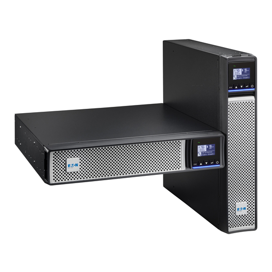
Page 7: Presentation
2 Presentation 2.1 Standard installation Tower installation Rack installation Description (UPS) Weights (lb/kg) Dimentions (inch/mm) D x W x H 5PX1500IRT2UAUG2 49.4/22,4 17.6x17.2x3.4/448x438x85,5 5PX2000IRT2UAUG2 61.7/28,0 23.7x17.2x3.4/603x438x85,5 5PX2200IRT2UAUG2 62.2/28,2 23.7x17.2x3.4/603x438x85,5 5PX2200IRT3UAUG2 60.6/27,5 19x17.2x5.1/483x438x129 5PX3000IRT2UAUG2 69.9/31,7 23.7x17.2x3.4/603x438x85,5 5PX3000IRT3UAUG2 68.6/31,1 19x17.2x5.1/483x438x129 Description (EBM) Weights (lb/kg) Dimentions (inch/mm) D x W x H 5PXEBM48RT2UG2... -
Page 8: Rear Panel
2.2 Rear panel ① UPS 5PX1500IRT2UAUG2 ② Input AC power source ③ Primary group (critical equipment) ④ Outlet group (programmable outlets) ⑤ USB communication port ⑥ RS232 communication port 5PX2200IRT2UAUG1 - 5PX3000IRT2U2AUG2 ⑦ Relay output contact ⑧ Connector for ROO (Remote On/Off) control and RPO (Remote Power Off) ⑨ Slot for optional communication card ⑩ Connector for additional External Battery Module... -
Page 9: Optional Accessories
Eaton Industrial Gateway Card (Modbus TCP / RTU) Relay-MS Eaton Relay card (1 x RS232 or 5 x Relay output) Environmental Monitoring Probe Gen2 Compatibility : Gigabit Network Card (Network-M2) / Industrial Gateway Card (INDGW-M2) / Eaton EMPDT1H1C2 ePDU G3/G3+ MBP3KIF... - Page 10 Package content Verify that the following additional items are included with the UPS: ① UPS ⑬ Connection cable to AC power source ⑭ Connection cables for the protected equipment ⑮ RS232 communication cable ⑯ USB communication cable ⑰ Safety instructions ⑱ Quick start ⑲ Cable locking systems ⑳ Rack kit for 19-inch enclosures ㉑ Two supports for tower position (tower feet) ㉒ Communication card (optional)
-
Page 11: Recommended Positions
3.2 Recommended positions Installation in tower position If you ordered other UPS accessories, refer to specific user manuals to check the tower installation with the UPS. To install the UPS: Place the UPS on a flat, stable surface in its final location. Always keep 6" or 150 mm of free space behind the UPS rear panel for ventilation. - Page 12 Installation in rack position Follow steps 1 to 4 for module mounting on the rails. The rails and necessary hardware are supplied by EATON. 614-40099-00...
-
Page 13: Ebm Connection
3.3 EBM Connection A small amount of arcing may occur when connecting an EBM to the UPS. This is normal and will not harm personnel. Insert the EBM cable into the UPS battery connector quickly and firmly. 1. Fix the rail on the back of the rack 2. -
Page 14: Ups Connection
Check that the indications on the name plate located on the back of the UPS correspond to the AC-power source and the true electrical consumption of the total load. 1. For the 5PX 1000 / 1500, connect the UPS input socket (2) to the AC power source using the cable of the protected equipment. -
Page 15: Connection With A Flexpdu (Power Distribution Unit) Module (Optional)
3.5 Connection with a FlexPDU (Power Distribution Unit) module (optional) 1. 5PX 1000 / 1500 : Use the power cable of the protected equipment. 5PX 2000 / 2200/ 3000 connect the UPS input socket to the AC power source using the cable (13) supplied. -
Page 16: Interfaces And Communication
UPS start-up with the HotSwap MBP module 1. Check that the UPS is correctly connected to the HotSwap MBP module. 2. Set switch (45) to Normal position. 3. Start the UPS by pressing the ON/OFF button on the UPS control panel. The load is supplied by the UPS. LED (43) "UPS ON - OK to switch"... -
Page 17: Lcd Description
Led indicator The following table shows the indicator status and description : Indicator Status Description Green The UPS is "On" and the load is protected The UPS is on battery mode Yellow Flashing The battery voltage is below the warning level The UPS has an active alarm or fault. -
Page 18: Display Functions
Operation status Possible cause Action In AVR mode The UPS is operating normally but the The UPS is powering the equipment through the utility voltage is outside normal mode Automatic Voltage Regulation device. The equipment is thresholds. still normally protected. No beep On Battery A utility failure has occurred and the... - Page 19 Clears faults UPS Type / Part Number / Serial Number / UPS Firmware / Comm card firmware / Comm card IPV4 Address / Comm card IPV6 Address / Comm card Identification MAC Address Registration Links to Eaton registration website 614-40099-00...
-
Page 20: User Settings
4.4 User settings The following table displays the options that can be changed by the user. Submenu Available settings Default settings [English] [Français] [Deutsch] [Español] [Русский] English [Português] [Italiano] [Simplified Chinese] [Japanese] Automatic message for user Language Menus, status, notices and alarms, UPS fault, Event Log configuration when UPS is data and settings are in all supported languages. - Page 21 Submenu Available settings Default settings [Yes] [No] [Timer] [10s] … [180s] Forced When mains recovers during a shutdown sequence: [Yes] reboot+ If set to Enabled, shutdown sequence will complete and [10s] timer? wait 10 seconds prior to restart, If set to Disabled, shutdown sequence will not complete, UPS stays on.
- Page 22 Submenu Available settings Default settings [0%] ... [100%] Automatic restart will occur only when the set percentage Restart batt. of battery charge is reached, and "Auto Restart" is enabled [0%] level and set to ON. A setting of 0% allows immediate automatic restart when utility returns after a UPS shutdown due to an extended power outage.
-
Page 23: Communication Ports
Submenu Available settings Default settings [DB9-7]: [On bat] [Low bat] [Bat fault] [UPS OK] [Load protected] [Load powered] [General alarm] [OVL pre- alarm] [DB9-8]: [On bat] [Low bat] [Bat fault] [UPS OK] [Load protected] [Load powered] [General alarm] [OVL pre- alarm] [Yes] [No] Remote... - Page 24 Connect the other end of the communication cable (15) or (16) to the USB (5) or RS232 (6) communication port on the UPS. The UPS can now communicate with Eaton power management software. Characteristics of the contact RS232 communication port Signal...
-
Page 25: Ups Remote Control Functions
Bypass. Programmable Signal Inputs The 5PX incorporates two programmable signal inputs: one Remote Power Off (RPO) input terminal, one Remote On/Off (ROO) input terminal, one RS-232 input (pin-4). Signal inputs can be configured (see Settings > Comm settings > Signal Input) to have one of the following functions: ... - Page 26 Function Description Active input turns UPS output (or outlet groups) off after a user defined shutdown delay but keeps on charging batteries according to a selected charging scheme; inactive input does not abort shutdown countdown. Depending on the Shutdown commands “Restart”...
-
Page 27: Eaton Intelligent Power Software Suite
It also gives you a complete record of critical power events, and it notifies you of important UPS or power information. If there is a power outage and the 5PX UPS battery power becomes low, Eaton Software suite can automatically shut down your computer system to protect your data before the UPS shutdown occurs. -
Page 28: Cybersecurity
4.8 Cybersecurity Eaton is committed to minimizing the Cybersecurity risk in its products and employs cybersecurity best practices and the latest cybersecurity technologies in its products and solutions, making them more secure, reliable and competitive for our customers. Eaton also offers Cybersecurity Best Practices whitepapers to its customers, referenced at www.eaton.com/cybersecurity. -
Page 29: Ups Shutdown
5.4 Operating modes The Eaton 5PX front panel indicates the UPS status through the UPS indicators located above the LCD screen. Normal mode When the green Sinewave symbol is illuminated, the UPS is providing protected AC power output. The UPS monitors and charges the batteries as needed and provides power protection to your equipment. -
Page 30: Ups Maintenance
If you store the equipment for a long period, recharge the battery every 6 months by connecting the UPS to utility power. The internal batteries charge to 90% capacity in less than 3 hours. However, Eaton recommends that the batteries charge for 48 hours after long-term storage. -
Page 31: Replacing Batteries
6.4 Replacing batteries DO NOT DISCONNECT the batteries while the UPS is in Battery mode. For battery replacement follow Eaton instructions provided on www.eaton.eu/BatteryServices Batteries can be replaced easily without turning off the UPS or disconnecting the load. Consider all warnings, cautions, and notes before replacing batteries. - Page 32 Replacing the internal battery : The internal battery is heavy. Use caution when handling the heavy batteries. A - Pull off the front panel by pressing on the both side B - Disconnect the battery block by separating the connectors (never pull on the wires). C - Remove the metal protection cover in front of the battery (three screws or two screws for 3U models).
-
Page 33: Replacing The Ups Equipped With A Hotswap Mbp
7 Troubleshooting The Eaton 5PX is designed for reliable, autonomous operation while providing you with notifications and alerts whenever a potential operational or performance issue occurs. Usually the alarms shown by the control panel do not mean that the output power is affected. Instead, they are preventive alarms intended to alert the user. -
Page 34: Typical Alarms And Faults
Use the following troubleshooting chart to determine the UPS alarm condition. 7.1 Typical alarms and faults The Eaton5PX are designed for durable, automatic operation and also alert you whenever potential operating problems may occur. Usually the alarms shown by the control panel do not mean that the output power is affected. Instead, they are preventive alarms intended to alert the user. - Page 35 The following table describes typical conditions: Conditions Possible cause Action Battery mode The UPS is powering the A utility failure has occurred and the UPS is in equipment with battery power. battery mode. Prepare your equipment for LED is On. shutdown.
-
Page 36: Silencing The Alarm
7.3 Service and support If you have any question or problem with the UPS, call Eaton or your local service representative in your country / region. Please have the following information ready when you call for service: •... -
Page 37: Extended Battery Module Model List
Description Catalog Number Power rating Configuration Eaton 5PX 3000i RT3U AU 5PX3000IRT3UAUG2 3000W/3000VA Rack / Tower 8.2 Extended Battery Module model list Model Catalog Number Configuration Battery voltage Use with Eaton 5PX EBM 48V 5PXEBM48RT2UG2 Rack / Tower 48Vdc 5PX1500IRT2UAUG2... -
Page 38: Electrical Input Connections
Default input Catalog Number Input nominal voltages Input voltage window (Voltage/Current) 5PX2200IRT3UAUG2 240V/16A 5PX3000IRT2UAUG2 240V/16A 5PX3000IRT3UAUG2 240V/16A 8.4 Electrical input connections Catalog Number Input connection Input cable 5PX1500IRT2UAUG2 IEC C14-10A Not provided 5PX2000IRT2UAUG2 5PX2200IRT2UAUG2 5PX2200IRT3UAUG2 IEC C20-16A Australia 15A 5PX3000IRT2UAUG2 5PX3000IRT3UAUG2 8.5 Electrical output All models... -
Page 39: Battery
Output conection Catalog Number Output cable 5PX1500IRT2UAUG2 (4) IEC10A (2) IEC10A group 1 (2) IEC10A group 2 5PX2000IRT2UAUG2 (2) IEC10A 5PX2200IRT2UAUG2 5PX2200IRT3UAUG2 (4) IEC10A + (1) IEC16A (2) IEC10A + (1) IEC16A group 1 5PX3000IRT2UAUG2 (2) IEC10A group 2 5PX3000IRT3UAUG2 8.7 Battery Internal batteries Internal batteries... -
Page 40: Glossary
Agency markings* CE, e-STAR, RCM Operating temperature 0 to 40 °C (32 to 104 °F) Storage temperature Transit temperature Relative humidity 20 to 90 % (without condensation) Up to 3,000 meters (9,843 ft) above sea level, no derating for 35°c (95°F) Operating altitude room temperature Transit altitude...
Need help?
Do you have a question about the 5PX and is the answer not in the manual?
Questions and answers