Eaton 5P 750 Installation And User Manual
Tower models & 1u rack models
Hide thumbs
Also See for 5P 750:
- Installation and user manual (35 pages) ,
- Installation and user manual (35 pages)
Table of Contents
Advertisement
Advertisement
Table of Contents

Related Manuals for Eaton 5P 750


Summary of Contents for Eaton 5P 750
-
Page 1: Tower Models
5P 750 5P 1000 5P 1500 5P 850G 5P 1550G 1U Rack models 5P 550 R 5P 750 R 5P 1000 R 5P 1500 R 5P 850G R 5P 1550G R Copyright © 2012 EATON All rights reserved. Service and support:... - Page 2 Page 2 620-00082-01-us (en)
-
Page 3: Important Safety Instructions
IMPORTANT SAFETY INSTRUCTIONS SAVE THESE INSTRUCTIONS. This manual contains important instructions that should be followed during installation and maintenance of the UPS and batteries. The 5P models that are covered in this manual are intended for installation in an environment within 0 to 40°C, free of conductive contaminant. -
Page 4: Safety Of Persons
• The system is not for use in a computer room AS DEFINED IN the standard for the Protection of Information Technology Equipment, ANSI/NFPA 75 (US installations only). Contact Eaton resellers to order a special battery kit, if needed to meet the ANSI/NFPA 75 requirement. Special Precautions • All handling operations will require at least two people (unpacking, installation in rack system). -
Page 5: Table Of Contents
Contents 1. Introduction ..................6 Environmental protection ....................6 2. Presentation ..................7 2.1 Standard installations ......................7 2.2 Tower rear panels .......................8 2.3 Rack rear panels ........................9 2.4 Control panel ........................10 2.5 LCD description ....................... 11 2.6 Display functions ......................12 2.7 User settings ........................ -
Page 6: Introduction
Before installing your 5P , please read the booklet presenting the safety instructions. Then follow the instructions in this manual. To discover the entire range of EATON products and the options available for the 5P range, we invite you to visit our web site at www.eaton.com/powerquality or contact your EATON representative. -
Page 7: Presentation
D x W x H 5P 550 R 17.80 / 8.08 14.3 x 17.2 x 1.7 / 363 x 438 x 43 5P 750 R 30.60 / 13.88 20.0 x 17.2 x 1.7 / 509 x 438 x 43 5P 1000 R 32.50 / 14.72... -
Page 8: Tower Rear Panels
2. Presentation 2.2 Tower rear panels 5P 750 / 5P 1000 (1) USB communication port (2) RS232 communication port (3) Slot for optional communication card (4) Connector for ROO (remote ON/OFF) or RPO (Remote Power OFF) control (5) Outlets for connection of critical... -
Page 9: Rack Rear Panels
2. Presentation 2.3 Rack rear panels 5P 550 R / 5P 750 R / 5P 1000 R (1) USB communication port (2) RS232 communication port (3) Slot for optional communication card (4) Connector for ROO (remote ON/OFF) or RPO (Remote Power OFF) control... -
Page 10: Control Panel
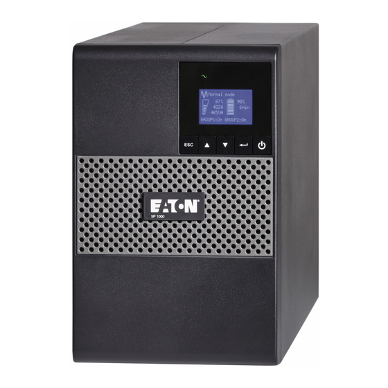
2. Presentation 2.4 Control panel The UPS has a five-button graphical LCD. It provides useful information about the UPS itself, load status, events, measurements and settings. Tower models Power On On battery Alarm Indicator Indicator (yel- Indicator (red) (green) low) Normal mode 100% 100% 720W 10min 800VA Efficiency: ~98% Escape Down Enter On/Off button Rack models Alarm On/Off Indicator (red) -
Page 11: Lcd Description
2. Presentation 2.5 LCD description Operation status Normal mode 100% 100% Load/equipment status 720W 10min Battery status 800VA Efficiency: ~98% Efficiency and load group information As default, or after 5 minutes of inactivity, the LCD displays the screen saver. The backlight LCD automatically dims after 10 minutes of inactivity. Press any button to restore the screen. The following table describes the status information provided by the UPS Note: If other indicator appears, see troubleshooting on page 18 for additional information. -
Page 12: Display Functions
2. Presentation 2.6 Display functions Press the Enter ( ) button to activate the menu options. Use the two middle buttons ( ) to scroll through the menu structure. Press the Enter ( ) button to select an option. Press the button to cancel or return to the previous menu. - Page 13 2. Presentation Description Available settings Default settings Load segments [Disable] [0s] [1 s] [2 s]…[65354 s] Group 1: Disable - Auto shutdown During a power outage, Group 2: Disable delay authorizes UPS to turn off power to equipment connected to Group 1 and/or Group 2 outlets.
-
Page 14: Installation
3. Installation 3.1 Unpacking and contents check Tower models Rack models (1) 5P UPS (2) Quick start and safety instructions (3) User manual and IPSS (Intelligent Power Software Suite) CD-ROM (4) RS232 communication cable (5) USB communication cable (6) 1U Rack kit (ears only for 550 R model) (7) Front panel parts (8) 2 connection cables for the protected equipments (850G and 1550G models) (9) Cable locking systems (1 x 4 outlets 850G R models;... -
Page 15: Battery Module Connection (Tower)
3. Installation 3.2 Battery module connection (Tower) Caution: Before starting the UPS, please connect the internal battery. Note: A small amount of arcing may occur when connecting the batteries. This is normal and does not damage the UPS or present any safety concern. A - Remove front panel. -
Page 16: Installation Of Tower Models
3. Installation 3.4 Installation of tower models 3.5 Installation of rack model for 2 post (option) Follow steps 1 to 5 for 2 post mounting. Use optional 1U 2 post rail kit. Page 16 620-00082-01-us (en) -
Page 17: Installation Of Rack Models (550 R)
3.6 Installation of rack models (550 R) Follow steps 1 to 3 for rack mounting. 3.7 Installation of rack models Follow steps 1 to 4 for module mounting on the rails. The rails and necessary hardware are supplied by EATON. Page 17 620-00082-01-us (en) -
Page 18: Installation Of Rack Model For Wall Mounting
3. Installation 3.8 Installation of rack model for wall mounting Page 18 620-00082-01-us (en) -
Page 19: Communication Ports
(6) to the USB (1) or RS232 (2) communication port on the UPS. The UPS can now communicate with EATON power management software. Installation of the communication cards (optional, standard on the Network bundle models) It is not necessary to shutdown the UPS before installing a communication card. -
Page 20: Operation
4.1 Start-up and Normal operation To start the UPS: 1. Verify that the UPS power cord is plugged in. 2. The UPS front panel display illuminates and shows EATON logo. 3. Verify that the UPS status screen shows 4. Press the button on the UPS front panel for at least 2 seconds. -
Page 21: Return Of Ac Input Power
4. Operation Low-battery warning • The indicator illuminates solid. • The audio alarm beeps every three seconds. The remaining battery power is low. Shut down all applications on the connected equipment because automatic UPS shutdown is imminent. End of battery backup time • LCD displays "End of backup time". -
Page 22: Maintenance
5. Maintenance 5.1 Troubleshooting Operation status Possible cause Action Batteries disconnected The UPS does not recognize If the condition persists, contact the internal batteries your service representative The batteries are disconnected Verify that all batteries are properly connected. If the condition persists, contact your service representative. -
Page 23: Battery-Module Replacement
Mounting the new battery module Carry out the above instructions in reverse order. • To ensure safety and high performance, use only batteries supplied by EATON. • Take care to firmly press together the two parts of the connector during remounting. -
Page 24: Mounting The New Battery Module
Mounting the new battery module Carry out the above instructions in reverse order. • To ensure safety and high performance, use only batteries supplied by EATON. • Take care to firmly press together the two parts of the connector during remounting. -
Page 25: Appendices
Charger Inverter Battery Tower 5P 750 5P 1000 5P 1500 Rack 5P 550 R 5P 750 R 5P 1000 R 5P 1500 R Output Power @ 120 V 550 VA 750 VA 1000 VA 1440 VA 420 W 600 W... - Page 26 6. Appendices 6.1 Technical specifications Transformer Filter Charger Inverter "AVR" Battery Tower 5P 850G 5P 1550G Rack 5P 850G R 5P 1550G R Output Power @ 230 V 850 VA 1550 VA 600 W 1100 W Output Power capacity 765 VA 1395 VA @ 208 V 540 W...
-
Page 27: Glossary
6. Appendices 6.2 Glossary Backup time Time during which the load can be supplied by the UPS operating on battery power. Battery test Internal UPS test to check battery status. Cold start The devices connected to the UPS can be started even if AC input power is not available. - Page 28 Page 28 620-00082-01-us (en)
Need help?
Do you have a question about the 5P 750 and is the answer not in the manual?
Questions and answers