Table of Contents
Advertisement
Quick Links
Advertisement
Table of Contents

Subscribe to Our Youtube Channel
Related Manuals for XtendLan XL-ICA-107M1C


Summary of Contents for XtendLan XL-ICA-107M1C
- Page 1 XL-ICA-107M1C Network 1,3Mpix CCD camera User’s Guide...
- Page 2 Thank you for purchasing our product. If there are any questions, or requests, please do not hesitate to contact the dealer. This manual may contain several technical incorrect places or printing errors, and the content is subject to change without notice. The updates will be added to the new version of this manual.
-
Page 3: Safety Instruction
User Manual of Network Camera Safety Instruction These instructions are intended to ensure that the user can use the product correctly to avoid danger or property loss. The precaution measure is divided into ‘Warnings’ and ‘Cautions’: Warnings: Serious injury or death may be caused if any of these warnings are neglected. Cautions: Injury or equipment damage may be caused if any of these cautions are neglected. - Page 4 User Manual of Network Camera Notice: 1. Make sure the power supply voltage is correct before using the camera. 2. Do not drop the camera or subject it to physical shock. 3. Do not touch CCD (Charge Coupled Device) modules with fingers. If cleaning is necessary, use a clean cloth with a bit of ethanol and wipe it gently.
-
Page 5: Table Of Contents
User Manual of Network Camera Index Chapter 1 Introduction ..............................1 1.1 Network camera Functions and Features ....................... 1 1.2 Applications ..............................2 Chapter 2 Installation..............................3 2.1 Panels Description ............................3 2.1.1 Side Elevation of the Camera ......................3 2.1.2 Rear Panel Description ........................ - Page 6 4.3.8 White Balance Settings ........................40 4.3.9 BACKLIGHT COMPENSATION....................41 4.3.10 Mirror mode settings........................42 Appendix 1 SADP Introduction..........................44 Appendix 2 Port Map ..............................46 Appendix 3 Pin Definition............................48 Appendix 4 Product Specification ..........................49 XL-ICA-107M1C.............................. 49 Specification .............................. 49 Dimension..............................50...
-
Page 7: Chapter 1 Introduction
User Manual of Network Camera Chapter 1 Introduction Network camera is a kind of embedded digital surveillance product that combines the features of both traditional analog camera and net DVS (Digital V ideo Server). Due to the embedded Linux operation system and the latest Davinci hardware platform of TI, the system operates with high scheduling efficiency. -
Page 8: Applications
User Manual of Network Camera Remote Control: The product offers a 10M/100M self-adaptive Ethernet interface. Support TCP / IP, HTTP, DNS, RTP / RTCP, PPPoE protocols. Set the parameters, browse real time videos or check the camera performance through software or IE, and get external alarming and store the compressed bit rate through network. -
Page 9: Chapter 2 Installation
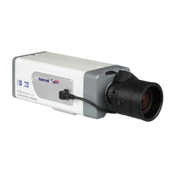
5. If the product does not operate properly, please contact your dealer or the nearest service center. Never attempt to disassemble the camera yourself. Users are responsible for any problem caused by modification or repairing without authorization. 2.1 Panels Description 2.1.1 Side Elevation of the Camera Fig 2.1.2 Side Elevation of XL-ICA-107M1C network camera... - Page 10 User Manual of Network Camera...
-
Page 11: Rear Panel Description
User Manual of Network Camera 2.1.2 Rear Panel Description Fig. 2.1.6 Rear Panel of XL-ICA-107M1C network camera 1. Standard Ethernet (UTP) RJ45 (10M/100M self-adaptive). 2. 1 channel voice talk input,3.5mm audio interface, 2.0~2.4Vp-p, 1kΩ. 3. 1 channel voice talk output, 3.5mm audio interface, electric line level, 600Ω. - Page 12 User Manual of Network Camera 8. Standard BNC for 1 channel video output. 9. GND. 10. Power supply indicate lamp. 11. Power supply interface of AC24V or DC12V.
- Page 13 User Manual of Network Camera SD card slot:Supports SDHC card, and the dimensions of SD meet the market’s normal standard. Fixed Screw: Loosen this screw to rotate the camera horizontally and vertically to adjust the pan and tilt position. When the camera angle is determined, lock the fixed screw to fix the camera.
-
Page 14: Product Installation
User Manual of Network Camera cable hole with a waterproof plug. 6. Lens: First, loosen the zoom lock handle, rotate it until there is an appropriate view angle between TELE and WIDE, then tighten the handle. Loosen the focus lock handle, rotate it until getting a clear image between NEAR and FAR, then tighten the handle. -
Page 15: Dome Camera Installation
User Manual of Network Camera Fig 2.2.1 Fix Ceiling Bracket Fig 2.2.2 Fix Camera Fig 2.2.3 Fix Lens 2.2.2 Dome camera Installation Dome camera can be installed include hold equipment, ceiling mounted, cylinders and other styles. Client can be installed in accordance with their own ways to achieve the installation.Please according the following specific steps to install (take ceiling mounted as example), when the wall is wood, use the self-tapping screws to fix the ceiling plate to the wall surface. -
Page 16: Vandal Proof Dome Camera Installation
User Manual of Network Camera Fig 2.2.4 Fix card Fig 2.2.5 Fix in Ceiling Take the three columns of Dome camera insert in the three fix slot of the ceiling plate. Pay attention to the direction of insertion. Let the ceiling plate “I” logo and the Dome camera “I” logo in the same direction. - Page 17 User Manual of Network Camera transparent cover shown as below: Fig. 2.2.8 Unload the Cover 2. Use the screws to fix the dome camera on the ceiling. Fig. 2.2.9 Install the Camera 3. Adjust the camera’s view angle while watching the video on the adjustment monitor. Loosen the fixed screws, and adjust horizontally and vertically the camera pan and tilt.
-
Page 18: Topological Graph Of Network Camera
User Manual of Network Camera Fig. 2.2.10 Install the Cover 2.2.4 Topological graph of network camera Megapixels Network Box Camera Application: Megapixels Network Dome Camera Application:... -
Page 19: Client Software Installation
User Manual of Network Camera Notice: Fig 2.1.12 Alarm output The alarm output is an on/off output that requires external power supply on connection. The external power supply shall be 12V DC/30mA, or use AC with external relays. Equipment damage or electric shock may cause if without relays. - Page 20 User Manual of Network Camera Fig.2.3.1 Client Software Installation Step2: Input “User Name”, “Company Name”; Fig.2.3.2 Customer Information Step3: Select the destination folder and click ‘Next’ to go to the next step.
- Page 21 User Manual of Network Camera Fig2.3.3 Ready to Install the Program Step4: Click ‘Install’ to start installation till finish the installation; Fig2.3.4 Installation Complete Click the ‘Finish’ button to close the dialog box. After the client software has been installed, you can find the remote client software through “Start” ->...
-
Page 22: Chapter 3 Parameter Configuration
User Manual of Network Camera Chapter 3 Parameter Configuration There are several network parameters of the camera which need to be set after the hardware installation. Those parameters including IP address, subnet mask and port number, etc. can be set through various kinds of methods, 2 of which are introduced as below. -
Page 23: Configuration Via Web Browser
User Manual of Network Camera Fig. 3.1.2 Select the device, and set its IP address and mask at the same network segment with the PC. The detailed introduction of SADP, please refer to Appendix 1. 3.2 Configuration via Web browser Before visit the camera via web browser, user should adjust security level. - Page 24 User Manual of Network Camera Fig. 3.2.1 Set the Security Level The default IP of the camera is 192.0.0.64 with 8000 as the default port, admin as the administrator,...
- Page 25 User Manual of Network Camera and 12345 as the password. The administrator can create up to 15 separate operators with different right levels. To login the camera through IE, input the IP address in the address column, and the “Login” dialog box will pop-up as Fig.
-
Page 26: Configuration Via Client Software
User Manual of Network Camera dialog box to pop up, and then set the parameters like IP address, etc. for your demand as Fig. 3.2.4. Enter the menu by invoking the 95 preset. Select the function you want by clicking the direction key. - Page 27 User Manual of Network Camera Fig.3.4.1 Register Administrator Enter the registered user name and password as Fig. 3.3.2. Click “Login” to enter the “Preview” menu as Fig. 3.3.3. Fig. 3.4.2 User Login Fig. 3.4.3 Preview Menu Click the “Configure” button in Fig. 3.3.4, and then right click the blank white space. Click the “Add Area”...
- Page 28 User Manual of Network Camera Fig. 3 .4.4 Add Area Fig. 3.4.5 Add Area Properties Input the area name (you can create whatever name you like) and click “OK” as Fig. 3.3.6. Then right click the area you have just created as Fig. 3.3.7.
- Page 29 User Manual of Network Camera Fig. 3.4.6 Area Name Adding Completed Fig. 3.4.7 Right Click the Area Name Click “Add Device”, and the “Add Device” dialog box will pop up as Fig. 3.3.8. Input your “Device Name”. Select “Normal” from “Register” option. Input your camera IP in “Device IP”, e.g. 192.0.0.64; “User Name”: admin, “Password”: 12345, and 8000 for the default “Port”, and then modify “Channel”...
- Page 30 User Manual of Network Camera Fig. 3.4.8 Add Device Fig.3.4.9 Camera Adding Completed Click the “Preview” button to enter the “Preview” menu as Fig. 3-3-10. Double click the channel name in the left tree to preview the camera feed.
- Page 31 User Manual of Network Camera Double click the channel Fig.3.4.10 Preview Menu Please refer to “Client Software-4000(v2.0)_ENG.pdf” for a more detailed parameters configuration. You can find the document in the PC Operating System after the installation of client software 4000 v.
-
Page 32: Visit Network Camera In Internet
User Manual of Network Camera 3.4 V isit Network Camera in Internet 3.4.1 V isit network camera with static IP When there is a static IP from an ISP, open some ports (such as 80 and 8000 ports) in the router. Then a user can visit it through a web browser or client software via the internet. -
Page 33: Visit Network Camera With Dynamic Ip
User Manual of Network Camera Fig.3.5.3 Selecting Normal Mode 3.4.2 V isit network camera with dynamic IP Fig.3.5.4 V isit camera through PPPoE dail-up This camera supports the PPPoE auto dial-up function, connecting the camera to a Modem for dial-up access to an ADSL network to get a public IP address; First, through local network access to the network camera, select “Configure””Right Click the Device”, Select “Remote Configuration”, Select “PPPoE Settings”... - Page 34 User Manual of Network Camera Fig.3.5.5 PPPoE configuration dialog box It is inconvenient to view a network camera with a dynamic IP, therefore, users should register with a dynamic DNS service provider. (Such as DynDns.com) Domain name resolution contains normal domain name resolution and private domain name resolution.
- Page 35 User Manual of Network Camera Input domain names in the client software or IE to view the network cameras. Take the client software configuration as an example. Fig.3.5.7 Selecting Normal Domain Mode 2. Private Domain Name Resolution Fig.3.5.8 Private Domain Name Resolution A PC with a static IP which is running the domain name resolution service is necessary.
- Page 36 User Manual of Network Camera camera’s name. And the server will find the camera from all the registered cameras and send its IP address to the client software. Once the client software gets the IP address, it can connect the network camera.
-
Page 37: Chapter 4 Menu Introduction
User Manual of Network Camera Chapter 4 Menu Introduction Note: In this chapter, we XL-ICA-107M1C as 1.3 megapixels CCD network camera. 4.1 Main Menu Call preset 95 and the menu will appear on the screen.”IRIS +” means “enter”, while “IRIS -” means “cancel”. -
Page 38: Menu Introduction Of 2.0 Megapixels Cmos Network Camera
User Manual of Network Camera The main menu displays as below: Fig.4.1.2 Main Menu 4.2 Menu Introduction of 2.0 Megapixels CMOS Network Camera 4.2.1 Language settings Press left / right to select language between Chinese and English; 4.2.2 Flicker Control Press left / right to select frequency between 50HZ and 60HZ in the FLICKER CONTROL item;... -
Page 39: Frame Settings
User Manual of Network Camera 4.2.4 Frame settings FRAME can’t be changed by pressing left / right button; User can select resolution through “configuration””remote configuration” “channel configuration ”“Frame rate”; The relationship between frame and resolution is as below table: Model Resolution Max. -
Page 40: Auto Gain Settings
User Manual of Network Camera HD720p 15fps 15fps 5fps UXGA 10fps 10fps 5fps 4.2.6 Auto Gain settings Press left / right to adjust AUTO GAIN level among OFF, low, middle and high; 4.2.7 DAY / NIGHT Settings Press left / right to select DAY / NIGHT mode among DAY, NIGHT and AUTO; Fig.4.2.1 DAY Mode... -
Page 41: White Balance Settings
User Manual of Network Camera Fig.4.2.2 NIGHT Mode 4.2.8 White Balance Settings Press left / right to set WHITE BALANCE AUTO or OFF; 4.2.9 Effect Mode settings Press left / right to select EFFECTS MODE among OFF, SPEIA, NEGTIVE, SOLARIZE1 and SLOARIZE2;... -
Page 42: Mirror Mode Settings
User Manual of Network Camera Fig.4.2.3 SEPIA Mode Fig.4.1.1 NEGATIVE Mode 4.2.10 Mirror mode settings Press left / right to select MIRROR mode among OFF, LEFT RIGHT, UP BOTTOM, and CENTER;... -
Page 43: Eptz Settings
User Manual of Network Camera 4.2.11 ePTZ settings Press left / right to set ePTZ ON or OFF; Under the resolution of QCIF/CIF/DCIF/2CIF/VGA/D1/SVGA, support pan\tilt\zoom operation, pan and tilt operation can be carried out only after zooming in,Support 127 preset positions (95 is excluded and used to call menu).Patrol path supports the preset of movement from Top left-hand corner of the screen to the bottom right-hand, supports 8 manual disposition patrols as well. -
Page 44: Language Settings
User Manual of Network Camera 4.3.1 Language settings Press left / right to select language between Chinese and English. 4.3.2 Resolution settings RESOLUTION can’t be changed by pressing left / right button; User can select resolution through client software, and the path is “configuration””remote configuration” “channel configuration ”“Resolution”. -
Page 45: Shutter
User Manual of Network Camera 4.3.5 Shutter Press left / right to adjust the exposure time from 1/25s, 1/50s, 1/100s, 1/250s, 1/500s, 1/1ks, 1/2ks, 1/4ks, 1/10ks, 1/100ks. 4.3.6 Auto Gain settings Press left / right to adjust AUTO GAIN level among OFF, low, middle and high; Note: When DAY / NIGHT mode is AUTO, AUTO GAIN is invalid. -
Page 46: White Balance Settings
User Manual of Network Camera Fig.4.2.2 NIGHT Mode 4.3.8 White Balance Settings Press left / right to set WHITE BALANCE ATW1, ATW2, ATC or MANUAL; ATW1: Camera uses TTL auto white balance algorithm to ideally recovery color, temperature range is from 2500K to 6500K. ATW2: Camera uses TTL auto white balance algorithm to ideally recovery color, temperature range is from 2500K to 15000K. - Page 47 User Manual of Network Camera settings, move the cursor to “back” and press confirm button ”IRIS+” to return to the previous menu. Note: When DAY / NIGHT mode is NIGHT, the WHITE BALANCE is invalid. Or DAY / NIGHT mode is AUTO, and the video is white and black, WHITE BALANCE is invalid too.
-
Page 48: Mirror Mode Settings
User Manual of Network Camera Move cursor to “POSITION”, and press “IRIS+” to enter the submenu; Press up / down / left / right to adjust the position of BLC area. After setting, press BACK to return to the previous menu. - Page 49 User Manual of Network Camera...
-
Page 50: Appendix 1 Sadp Introduction
User Manual of Network Camera Appendix 1 SADP Introduction 1. Brief introduction SADP (Search Active Devices Protocol), can automatically search IP cameras in LAN. User can modify the IP address, subnet mask and port of the device without visiting IP address of the device. Additionally, password of the super user in this device can be recovered as default. - Page 51 User Manual of Network Camera Input the new IP address, subnet mask, and port number, and click ‘save’ button. If a dialog pops up, showing ‘saved successfully’, that means you have modified the configuration information; if ‘saving failed’ dialog pops up, click the ‘cancel’...
-
Page 52: Appendix 2 Port Map
User Manual of Network Camera Appendix 2 Port Map Note: The following setting is about TP-LINK router (TL-R410), which is maybe distinct from other router’s setting. 1. Firstly, select the router’s WAN connection Type. As the following Fig. shows: 2. Set the “network parameter” of the router as the below figure. The setting includes subnet mask and gateway. 3. - Page 53 User Manual of Network Camera As the above mentioned setting, we map the router’s port 80, 8000, 554, 8200 to the network camera 192.168.1.23; and port 81, 8001, 555, 8201 to the network camera 192.168.1.24. In this way, user can visit the 192.168.1.23 through visiting the router’s port 80, 8000, 554 and 8200.
-
Page 54: Appendix 3 Pin Definition
User Manual of Network Camera Appendix 3 Pin Definition (1)UTP between the network port of camera and HUB (Direct Cable) (2)UTP between the network port of camera and PC (Cross Cable):... -
Page 55: Appendix 4 Product Specification
User Manual of Network Camera Appendix 4 Product Specification XL-ICA-107M1C Specification Parameter Model XL-ICA-107M1C Camera Image Sensor 1/3 inch SONY progressive scan CCD Effective Pixels 1280 (H) × 960 (V), 1.3M CCD Min. Illumination Color: 0.1Lux @ F1.2, B / W: 0.01Lux @ F1.2... -
Page 56: Dimension
User Manual of Network Camera Others -10°C ~ 60°C Working Temperature Power Supply AC24V, ±10% / DC12V, ±10%, PoE (Power over Ethernet). Power Consumption 4W MAX (10W max with ICR working) Dimensions (mm) 68.5 x 63 x 157.5 2.71” x 2.5” x 6.25” (1.32lbs) Weight 600g...
Need help?
Do you have a question about the XL-ICA-107M1C and is the answer not in the manual?
Questions and answers