
Subscribe to Our Youtube Channel
Related Manuals for XtendLan XL-ICA-306M3


Summary of Contents for XtendLan XL-ICA-306M3
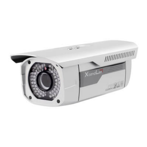
- Page 1 HD IR Waterproof Fixed IP Camera User’s Manual XL-ICA-306M3 HD IR Waterproof Fixed IP Camera User's guide Version 3.5.0...
- Page 2 Welcome Thank you for purchasing our IP camera! This user’s manual is designed to be a reference tool for your system. Please read the following safeguard and warnings carefully before you use this series product! Please keep this user’s manual well for future reference!
-
Page 3: Important Safeguards And Warnings
Important Safeguards and Warnings 1.Electrical safety All installation and operation here should conform to your local electrical safety codes. The power shall conform to the requirement in the SELV (Safety Extra Low Voltage) and the Limited power source is rated 12V DC or 24V AC in the IEC60950-1. We assume no liability or responsibility for all the fires or electrical shock caused by improper handling or installation. - Page 4 Please put the dustproof cap to protect the CCD (CMOS) component when you do not use the camera. 7. Accessories Be sure to use all the accessories recommended by manufacturer. Before installation, please open the package and check all the components are included. Contact your local retailer ASAP if something is broken in your package.
-
Page 5: Table Of Contents
Table of Contents General Introduction ........................1 Overview ........................1 Features.........................1 Specifications ........................2 1.3.1 Performance......................2 1.3.2 Factory Default Setup ...................3 Structure ............................11 Multiple-function Combination Cable ..............11 Framework and Dimension..................12 Bidirectional talk ......................13 2.3.1 Device-end to PC-end ..................13 2.3.2 PC-end to the device-end ..................13 Alarm Setup.........................13 Device Installation ........................15 Quick Configuration Tool......................16... -
Page 6: General Introduction
1 General Introduction 1.1 Overview This series IP camera integrates the traditional camera and network video technology. It adopts audio and video data collection, transmission together. It can connect to the network directly without any auxiliary device. This series IPC uses standard H.264 video compression technology and G.711a audio compression technology, which maximally guarantee the audio and video quality. -
Page 7: Specifications
The enclosure conforms to the IP 66 protection. Has the waterproof function. 1.3 Specifications 1.3.1 Performance Please refer to the following sheet for IPC performance specification. Model XL-ICA-306M3 Parameter TI Davinci high performance DSP Main Processor Embedded LINUX Support real-time network, local record, and remote operation at the System same time. -
Page 8: Factory Default Setup
Support mirror and flip function. Video Flip Max 1f/s snapshot. File extension name is JPEG. Snapshot Supports max 4 privacy mask zones Privacy Mask Support parameter setup such as bright, contrast. Video Setup Video Channel title, time title, motion detect, camera masking. Information 8~16mm @F1.6 8~20mm@F1.6... - Page 9 Please refer to the following sheet for factory default setup information. Default Setup Setup Item XL-ICA-306M3 Brightness Contrast Saturation Gain Mode Auto Gain Limit Exposure Mode Auto Auto Iris Scene Mode Auto Day/night Mode Auto Mirror Flip Bit stream General...
- Page 10 Default Setup Setup Item XL-ICA-306M3 Bit Rate Type Recomme 192-1024Kb/S nded Bit Bit Rate 1024 I Frame Snapshot General Type Image 1080P(1920*1080) 720P(1280*720) Snapshot Size Quality Interval Privacy Disable Mask Video Overlay Channel Enable Title Time Title Enable Snapshot C:\PictureDownload...
- Page 11 Default Setup Setup Item XL-ICA-306M3 Enable Enable ARP/Ping set device IP address service Connectio TCP Port 37777 UDP Port 37778 Connection HTTP Port RTSP Port HTTPs Port Enable Disable PPPoE Username Password Server Disable,CN99 DDNS Type Server IP none Server...
- Page 12 Default Setup Setup Item XL-ICA-306M3 (Encryptio n mode) Title IPC Message (Subject) Attachmen Enable Mail Receiver Send 0 second Interval Email Test Disable,interval=60 minutes Enable UPnP Disable UPnP SNMP v1 Disable SNMP v2 Disable SNMP Port Read Communit public SNMP...
- Page 13 Default Setup Setup Item XL-ICA-306M3 Sensitivity Record Enable Channel Record 10 seconds Delay Relay out Enable Alarm 10 seconds Delay Send Disable Email Snapshot Disable Enable Disable Record Enable Channel Record 10 seconds Delay Video Relay out Enable Masking Record...
- Page 14 Default Setup Setup Item XL-ICA-306M3 Warning Capacity Limit Relay out Enable Relay out 10 seconds Delay Send Disable Email Enable Disable Relay out Enable Card Relay out 10 seconds Error Delay Send Disable email Enable Disable Record Enable Record Disconnect...
- Page 15 Default Setup Setup Item XL-ICA-306M3 Device No Device factory SN Language English Local Host Video Standard Date Y-M-D Format Time Format Time Zone GMT+08:00 System Sync Time Disable Date DST Type Week time Start Time 00:00:00 of the first Sunday of the month...
-
Page 16: Structure
2 Structure 2.1 Multiple-function Combination Cable You can refer to the following figure for multiple-function combination cable information. See Figure Figure 2-1 Please refer to the following sheet for detailed information. Port Name Function Connection Note Video output Output analog video signal. It can connect to the VIDEO OUT port TV monitor to view the video. -
Page 17: Framework And Dimension
Port Name Function Connection Note Power port. Input DC 12V or AC 24V. Please note: Connect the DC5.5 round port to 2-pin Power input converter cable (Provided) when you are POWER port using AC 24V series product. The DC5.5 round port to 2-pin converter cable is not included in the accessories bag if you are using DC 12V series product. -
Page 18: Bidirectional Talk
Figure 2-3 2.3 Bidirectional talk 2.3.1 Device-end to PC-end Device Connection Please connect the speaker or the pickup to the first audio input port in the device rear panel. Then connect the earphone or the sound box to the audio output port in the PC. Login the Web and then enable the corresponding channel real-time monitor. - Page 19 4) Set the WEB alarm output. The alarm output 01 is for the alarm output port of the device. It is the No.2 pin of the I/O cable. Figure 2-4 Please refer to the following figure for alarm input information. See Figure 2-5. Alarm input: When the input signal is idle or grounded, the device can collect the different statuses of the alarm input port.
-
Page 20: Device Installation
3 Device Installation Please follow the steps listed below to install the device. Please refer to Figure 3-1 for reference. Please line up the installation holes of the bottom of the device to the installation holes in the front part of the bracket. Then insert the screws to the holes to fasten the device on the bracket. -
Page 21: Quick Configuration Tool
4 Quick Configuration Tool 4.1 Overview Quick configuration tool can search current IP address, modify IP address. At the same time, you can use it to upgrade the device. Please note the tool only applies to the IP addresses in the same segment. 4.2 Operation Double click the “ConfigTools.exe”icon, you can see an interface is shown as in Figure 4-1. - Page 22 Select the “Open Device Web” item; you can go to the corresponding web login interface. See Figure 4-3. Figure 4-3 If you want to modify the device IP address without logging in the device web interface, you can go to the configuration tool main interface to set.
- Page 23 Figure 4-5...
-
Page 24: Web Operation
5 Web Operation This series IPC product support the Web access and management via PC. Web includes several modules: monitor channel preview, system configuration, alarm and etc. 5.1 Network Connection Please follow the steps listed below for network connection. Make sure the IPC has connected to the network properly. Please set the IP address, subnet mask and gateway of the PC and the IPC respectively. - Page 25 Figure 5-2 If it is your first time to login in, system pops up warning information to ask you whether install control webrec.cab or not after you logged in for one minute. Please click OK button, system can automatically install the control. When system is upgrading, it can overwrite the previous Web too. If you can’t download the ActiveX file, please check whether you have installed the plug-in to disable the control download.
- Page 26 Figure 5-4 Please refer to the Web Operation Manual included in the resource CD for detailed operation instruction.
-
Page 27: Faq
6 FAQ I can not boot up Please click RESET button for at least five seconds to restore the device. factory default setup. card write Do not set the SD card as the storage media to storage the times schedule record file. It may damage the SD card duration. I can not use the When disk information is shown as hibernation or capacity is 0, please format it first (Via Web). -
Page 28: Appendix Toxic Or Hazardous Materials Or Elements
Appendix Toxic or Hazardous Materials or Elements Toxic or Hazardous Materials or Elements Component Name Cr VI PBDE Circuit Board ○ ○ ○ ○ ○ ○ Component Device Construction ○ ○ ○ ○ ○ ○ Material Wire and Cable ○ ○...
Need help?
Do you have a question about the XL-ICA-306M3 and is the answer not in the manual?
Questions and answers