Advertisement
Quick Links
Advertisement

Related Manuals for Centro 2800 G41201


Summary of Contents for Centro 2800 G41201
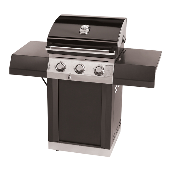
- Page 1 Centro 2800 Assembly Manual 85-1614-2 (G41201) Propane 85-1650-4 (G41202) Natural Gas Limited 3-Year Warranty Read and save manual for future reference. Assemble your grill immediately. Missing or damaged parts should be claimed within 15 days of purchase. Manual Revision #:...
- Page 2 H E A V Y A R T I C L E N E E D S 2 T O L I F T THIS MANUAL MUST REMAIN WITH THE PRODUCT AT ALL TIMES To ORDER non-warranty replacement parts or accessories, or to register your warranty, please visit us on the web at www.centrobbqs.com.
-
Page 3: Hardware Pack
HARDWARE PACK TOOLS NEEDED FOR ASSEMBLY No. Description Part Number Quantity 1/4"-20UNCX13 Screw 20120-13013-250 • #2 Phillips screwdriver (long and short) 1/4"-20UNCX38 Screw 20120-13038-250 • ¼” Slotted screwdriver (long and short) 1/4"-20UNCX16 Screw 20120-13016-250 • Adjustable wrench ø7 Lock Washer 41400-07000-250 •... -
Page 4: Parts List
PARTS LIST (PROPANE) FOR 85-1614-2 (G41201) Item No. Quantity Description Part No. Top Lid G412-0100-01 Lid handle G412-0004-01 Lid handle end cap-Left G617-0004-01 Lid handle end cap-Right G617-0005-01 Logo Plate G412-0001-01 Thermometer G412-0003-01 Screw for Top Lid G501-0005-01 Lid Bumper G508-0063-01 Burner Box Weldment G412-0200-01... - Page 5 EXPLOADED DIAGRAM (PROPANE) FOR 85-1614-2 (G41201) Heat shield Assembly Manual Safety & Care Manual...
- Page 6 PARTS LIST (NATURAL GAS) FOR 85-1650-4 (G41202) Item No. Quantity Description Part No. Top lid G412-0100-01 Lid handle G412-0004-01 Lid handle end cap-Left G617-0004-01 Lid handle end cap-Right G617-0005-01 Logo plate G412-0001-01 Thermometer G412-0003-01 Screw for top lid G501-0005-01 Lid bumper G508-0063-01 Burner box weldment G412-0200-01...
- Page 7 EXPLOADED DIAGRAM (NATURAL GAS) FOR 85-1650-4 (G41202) Heat shield Assembly Manual Safety & Care Manual...
-
Page 8: Assembly Instructions
ASSEMBLY INSTRUCTIONS 1. Separate the 2 different types of wheels, 2 locking wheels (DJ) and 2 regular wheels (DK). Attach the locking wheels (DJ) to the back of the bottom shelf (DI) and the regular wheels (DK) to the front of the bottom shelf (DI). To secure the 4 wheels, hand tighten first. - Page 9 ASSEMBLY INSTRUCTIONS 3. Assemble the Left and right Pillars (DG), to the cart side panels, as shown in figure A and B. #6 - NO. 10-24UNCx10 Screw (x6) #7 - ø5 Lock Washer (x6) #8 - ø5 Washer (x6) 4. Attach the front panel (DH) onto the pillars (DG). #6 - NO.
- Page 10 ASSEMBLY INSTRUCTIONS 5. Position the top lid and burner box assembly (A and B) onto the cart assembly (C) as shown. in figure A. Use the hardware to connect both parts, on the left and right sides, at the two points indicated in Figure B.
- Page 11 ASSEMBLY INSTRUCTIONS 7. Attach the right side shelf fascia(DD) to the right side shelf (DC). Front #6 - NO. 10-24UNCx10 Screw (x3) #7 - ø5 Lock Washer (x3) #8 - ø5 Washer (x3) Back TIP: To position the side shelf, insert the two hooks on the side right shelf assembly into the two open- ings located on the upper right side panel (BC).
- Page 12 ASSEMBLY INSTRUCTIONS 9. Attach the left shelf fascia (DB) to the left side shelf (DA). Front #6 - NO. 10-24UNCx10 Screw (x3) #7 - ø5 Lock Washer (x3) Back #8 - ø5 Washer (x3) TIP: To position the side shelf, insert the two hooks on the side shelf assembly into the two openings located on the upper side panel (BE).
- Page 13 ASSEMBLY INSTRUCTIONS 11. Place the heat shield (CG) into the groove which is located at the back side of the front panel as shown in figure A. Next, attach the heat shield (CG) to the upper back panel (BI) by using the self tapping screw (x2), as shown in figure B.
- Page 14 ASSEMBLY INSTRUCTIONS 13a. Insert the grease tray (CI) into the opening in the upper back panel (BI), making sure to engage tracks located under burner box. 13b. Place the grease cup (CJ) onto the tracks, located opn the underside of the grease tray (CI).
- Page 15 ATTENTION: For your families safety, do not attempt to light this BBQ until you have reviewed pages 4-7 of the CENTRO Safe Use and Care Manual. All Safety and Leak test MUST BE PERFORMED BY THE END USER, prior to lighting this BBQ.
Need help?
Do you have a question about the 2800 G41201 and is the answer not in the manual?
Questions and answers