Advertisement
Quick Links
Advertisement

Subscribe to Our Youtube Channel
Related Manuals for Centro Centro 5800


Summary of Contents for Centro Centro 5800
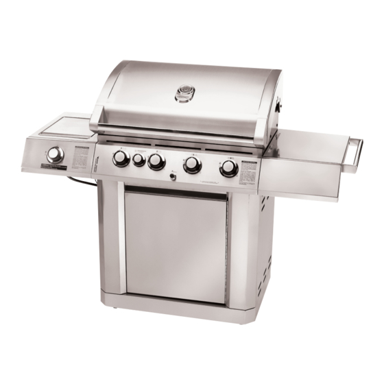
- Page 1 Centro 5800 Assembly Manual 85-1628-0 (G61701) Propane 85-1653-8 (G61703) Natural Gas Limited 5-Year Warranty Read and save manual for future reference. Assemble your grill immediately. Missing or damaged parts should be claimed within 15 days of purchase. Manual Revision #:...
- Page 2 H E A V Y A R T I C L E N E E D S 2 T O L I F T THIS MANUAL MUST REMAIN WITH THE PRODUCT AT ALL TIMES To ORDER non-warranty replacement parts or accessories, or to register your warranty, please visit us on the web at www.centrobbqs.com.
-
Page 3: Hardware Pack
HARDWARE PACK TOOLS NEEDED FOR ASSEMBLY No. Description Part Number Quantity ¼"×38mm Screw 20120-13038-250 • #2 Phillips screwdriver (Long and short) ¼"×16mm Screw 20120-13016-250 • ¼” Slotted screwdriver ¼"×13mm Screw 20120-13013-250 • Adjustable wrench ø7 Lock Washer 41400-07000-250 • Pliers ø7 Washer 40300-07000-250 •... -
Page 4: Parts List
PARTS LIST (PROPANE) FOR 85-1628-0 (G61701) Item Qty. Description Part No. Item Qty. Description Part No. Top Lid Assembly G617-0100-01 Front Brace G617-0023-01 Lid Inner Insert G617-0001-01 Upper Back Panel G617-2700-01 Lid handle G617-0003-01 Tank Exclusion G617-0037-01 Lid handle end cap-Left G617-0004-01 Lid handle end cap-Right G617-0005-01... - Page 5 EXPLOADED DIAGRAM (PROPANE) FOR 85-1628-0 (G61701) Assembly Manual Safety & Care Manual...
- Page 6 PARTS LIST (NATURAL GAS) FOR 85-1653-8 (G61703) Item Qty. Description Part No. Item Qty. Description Part No. Top Lid assembly G617-0100-01 Grease Cup G416-0015-01 Lid Inner Insert G617-0001-01 Front Brace G617-0023-01 Lid handle G617-0003-01 Upper Back Panel G617-2700-01 Lid handle end cap-Left G617-0004-01 Lid handle end cap-Right G617-0005-01...
- Page 7 EXPLOADED DIAGRAM (NATURAL GAS) FOR 85-1653-8 (G61703) Assembly Manual Safety & Care Manual...
-
Page 8: Assembly Instructions
ASSEMBLY INSTRUCTIONS 1. Separate the 2 different types of wheels, 2 locking wheels (EI) and 2 regular wheels (EJ). Attach the locking wheels (EI) to the back of the bottom shelf (EH) and the regular wheels (EJ) to the front of the bottom shelf (EH). - Page 9 ASSEMBLY INSTRUCTIONS 3. Attach the Front Brace (CN) to the Left and right cart side panels (EA and EB) TIP: One person should align the left side, while the second person assembles the right side. #6 - NO. 10x10 Screw (x4) #7 - ø5 Lock Washer (x4) #8 - ø5 Washer (x4) Back view...
- Page 10 ASSEMBLY INSTRUCTIONS 5. Attach the cart back panel (EG) to the rear of the left and right cart side panels (EA and EB). #3 - 1/4” × 13mm Screw (x4) #4 - ø7 Lock Washer (x4) #5 - ø7 Washer (x4) Right side Left side THIS STEP REQUIRES 3 OR MORE PEOPLE.
- Page 11 ASSEMBLY INSTRUCTIONS 7. Attach the upper back panel (CO) to both the left and right side panels (EA and EB). Only install hardware in the bottom portion of the back panel, as shown in figure B. #1 - ¼”×38mm Screw (x2) #4 - ø7 Lock Washer (x2) Back view #5 - ø7 Washer (x2)
- Page 12 ASSEMBLY INSTRUCTIONS TIP: To position the right side shelf, insert the two hooks on the side shelf assembly into the two openings located on the right upper side panel (BC). 9. Assemble the right side shelf assembly to the cart assembly, as shown in figure B.
- Page 13 ASSEMBLY INSTRUCTIONS TIP: To position the left side shelf, insert the two hooks on the side shelf assembly into the two openings located on the upper left side panel (BB). 11. Assemble the right side shelf assembly to the cart assembly, as shown in figure B.
- Page 14 ASSEMBLY INSTRUCTIONS 13a. Position the side burner (DD) through the opening in the left side shelf (DA). 13b. Make sure that the burner engages the side burner valve as shown as shown in figure B. Underside view 13c. Using the Wing nut provided, assemble the side burner to the side burner drip pan (DC), as shown in figure C.
- Page 15 ASSEMBLY INSTRUCTIONS 13d. Attach the end of the side burner electrode wire (DE) to the underside of the side burner electrode, as shown in figure D. Ensure that the wire is pushed in firmly. 13e. Place the side burner cooking grate(DG) into postion on the side burner shelf, as shown in figure E.
- Page 16 ASSEMBLY INSTRUCTIONS TIP: Before attempting to assemble the door (EF) to the right pillar (ED), locate the two clasps on the door Hinge. Next, locate the two small openings on the right side pillar. 15a. Hold the door perpendicular to the BBQ Cart. Align the two clasps on the door hinge (EF), with the two holes on the right side pillar (ED).
- Page 17 ASSEMBLY INSTRUCTIONS 17a. Place the cooking grates (BH) into the burner box, as shown in figure A. 17b. Insert the three small positioning rods of the warming rack (BI) into the rotisserie burner brace (BA4) 18a. Insert the grease tray (CL) into the opening in the upper back panel (CO), making sure to engage tracks located under burner box.
- Page 18 ATTENTION: For your families safety, do not at- tempt to light this BBQ until you have reviewed pages 4-7 of the CENTRO Safety & Care Manual. All Safety and Leak test MUST BE PERFORMED BY THE END USER, prior to lighting this BBQ.
- Page 19 ASSEMBLY INSTRUCTIONS For natural gas model only. 21. Attach the Natural Gas Hose(CB) to the side burner valve(CC) as shown.
Need help?
Do you have a question about the Centro 5800 and is the answer not in the manual?
Questions and answers