
Related Manuals for HP ProCurve 2224


Summary of Contents for HP ProCurve 2224
-
Page 1: Installation Guide
ProCurve Switches and Hubs HP ProCurve Switch 2224 Installation Guide L e s s Wo r k , M o r e N e t w o r k h t t p : / / w w w . h p . c o m / g o / p r o c u r v e... - Page 3 HP ProCurve Switch 2224 Installation Guide...
- Page 4 A copy of the specific warranty terms applicable to your Hewlett-Packard products and replacement parts can be obtained from your HP Sales and Service Office or authorized dealer. Safety Before installing and operating this product, please read the “Installation Precautions”...
-
Page 5: Table Of Contents
Contents 1 Introducing the HP Switch 2224 Front of the Switch ..........1-2 Network Ports . - Page 6 Testing End-to-End Network Communications ....3-6 HP Customer Support Services ....... . . 3-6 A Specifications Physical .
-
Page 7: Introducing The Hp Switch 2224
Introducing the HP Switch 2224 The HP ProCurve Switch 2224 is a multiport switch that can be used to build high-performance switched workgroup networks. This switch is a store-and- forward device that offers low latency for high-speed networking. HP ProCurve Switch 2224 (HP J4095A) Throughout this manual, this switch will be abbreviated as the Switch 2224. -
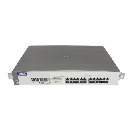
Page 8: Front Of The Switch
Introducing the HP Switch 2224 Front of the Switch Front of the Switch Link and Mode LEDs Slot for 10/100Base-TX RJ-45 ports Power Fault for each 100Base-FX Transceiver port Reset button Port 1 indicator LED Mode Select button and indicator LEDs... -
Page 9: Leds
Introducing the HP Switch 2224 Front of the Switch LEDs Table 1-1. Switch LEDs Switch LEDs State Meaning Power The switch is receiving power. (green) The switch is NOT receiving power. Fault The normal state; indicates that there are no fault conditions on the switch. -
Page 10: Mode Select Button And Indicator Leds
Introducing the HP Switch 2224 Front of the Switch Mode Select Button and Indicator LEDs To optimize the amount of information that can be displayed for each of the switch ports without overwhelming you with LEDs, the Switch 2224 uses a Mode LED for each port. -
Page 11: Back Of The Switch
Introducing the HP Switch 2224 Back of the Switch Back of the Switch AC power connector Power Connector The Switch 2224 does not have a power switch; it is powered on when connected to an active AC power source. The switch automatically adjusts to any voltage between 100-127 and 200-240 volts and either 50 or 60 Hz. -
Page 12: Features
The features of the Switch 2224 include: 24 auto-sensing 10/100Base-TX RJ-45 ports a slot for installing an HP 100Base-FX Transceiver Module (HP J3193B) plug-and-play networking—all ports are enabled—just connect the network cables to active network devices and your switched network is operational automatic learning of the hardware addresses in the switch’s 12000-entry... -
Page 13: Simultaneous Network Communications
Introducing the HP Switch 2224 Switch Operation Overview flood - whenever a new destination address is found in a packet received on a port, the destination address will not yet be in the switch’s address table and the Switch 2224 cannot know whether to forward or filter out the packet. -
Page 15: Installing The Switch 2224
Installing the Switch 2224 The HP Switch 2224 is easy to install. It comes with an accessory kit that includes the brackets for mounting the switch in a standard 19-inch telco rack or an equipment cabinet, or on a wall, and with rubber feet that can be attached so the switch can be securely located on a horizontal surface. -
Page 16: Installation Procedures
(Optional) Install the transceiver module. The Switch 2224 has a slot for installing an HP 100Base-FX fiber-optic transceiver module (HP J3193B). Depending on where you will locate the Switch 2224, it may be easier to install the transceiver first. -
Page 17: Installation Precautions
Installing the Switch 2224 Installation Procedures Installation Precautions: Follow these precautions when installing your HP Switch 2224. W a r n i n g The rack or cabinet should be adequately secured to prevent it from becoming unstable and/or falling over. -
Page 18: Prepare The Installation Site
Installing the Switch 2224 Installation Procedures 1. Prepare the Installation Site Cabling Infrastructure - Ensure that the cabling infrastructure meets the necessary network specifications. See the following table for cable types and lengths, and see appendix B, “Cables and Connectors” for more information: Table 2-1. -
Page 19: Install An Optional Transceiver
Installing the Switch 2224 Installation Procedures 2. Install An Optional Transceiver Install an optional transceiver module into the transceiver slot as shown in the illustration below, or by following the instructions in the manual that comes with the transceiver. The slot cover can be removed with either a flat-bladed or Torx T-10 screw- driver. -
Page 20: Verify The Switch Operates Correctly
Installing the Switch 2224 Installation Procedures 3. Verify the Switch Operates Correctly After you have optionally installed a transceiver module, but before mounting the switch in its network location, you should first check that it is working properly by plugging it into a power source and verifying that it passes its self test. - Page 21 Installing the Switch 2224 Installation Procedures switch port LEDs Power and Fault LEDs When the switch is powered on, it performs its diagnostic self test. The self test takes approximately 3 seconds to complete. LED Behavior: During the self test: •...
-
Page 22: Mount The Switch
Installing the Switch 2224 Installation Procedures 4. Mount the Switch After a transceiver has been installed and you have verified that the switch passes its self test, you are ready to mount the switch in a stable location. The Switch 2224 can be mounted in these ways: in a rack or cabinet on a horizontal surface on a wall... - Page 23 Installing the Switch 2224 Installation Procedures Partially install a screw (5/8-inch number 12-24) into the top hole of a pair of holes that are 0.5 inches apart in each rack/cabinet upright as shown in the illustration below. Ensure that the screws are at the same level in each upright.
- Page 24 Installing the Switch 2224 Installation Procedures Install the other number 12-24 screw into the upper hole in each bracket. Tighten these screws. install additional screw Wall Mounting You can mount the switch on a wall as shown in the illustration below. C a u t i o n The switch should be mounted only to a wall or wood surface that is at least 1/2-inch plywood or its equivalent.
-
Page 25: Connect The Switch To A Power Source
Installing the Switch 2224 Installation Procedures Attach the switch to the wall or wood surface with 5/8-inch number 12 wood screws (not included). 5/8-inch wood screw Horizontal Surface Mounting Attach the rubber feet included in the accessory kit to the bottom of the switch, then place the switch on a table or other horizontal surface. -
Page 26: Connect The Network Cables
Installing the Switch 2224 Installation Procedures 6. Connect the Network Cables Using the RJ-45 Connectors (10/100Base-TX ports) To connect: Push the RJ-45 plug into the RJ-45 jack until the tab on the plug clicks into place. When power is on for the switch and for the connected device, the Link LED for the port should light to confirm a powered-on device (for... -
Page 27: Sample Network Topologies
Installing the Switch 2224 Sample Network Topologies Sample Network Topologies This section shows you a few sample network topologies in which the Switch 2224 is implemented. As a Desktop Switch Server Switch 2224 twisted-pair “straight-through” cables PCs and peripherals The Switch 2224 is designed to be used primarily as a desktop switch to which end nodes, printers and other peripherals, and servers are directly connected, as shown in the above illustration. -
Page 28: As A Segment Switch
Installing the Switch 2224 Sample Network Topologies As a Segment Switch 100 Mbps connection through category 5 Server twisted-pair “straight-through” cable Switch 2224 twisted-pair “crossover” cables 100 Base-FX fiber-optic cable Ethernet to backbone Hubs PCs, printers, and local servers twisted-pair “straight-through”... -
Page 29: Connecting To A Backbone Switch
The simpler desktop and segment networks shown in the previous two examples can easily be combined and expanded. For example, you could use an HP ProCurve Switch 8000M to interconnect each of your smaller switched workgroups to form a larger switched network. All the devices in this network can communicate with each other. -
Page 31: Troubleshooting
(page 3-1) diagnosing with the LEDs (page 3-3) hardware diagnostic tests (page 3-5) HP Customer Support Services (page 3-6) Basic Troubleshooting Tips Most problems are caused by the following situations: Incorrect switch-to-switch or switch-to-hub connections. If you... - Page 32 Refer to the Network Design Guide for topology configuration guidelines. This guide can be found online at the HP World Wide Web site for networking products, http://www.hp.com/go/ procurve. You can find it quickly by searching for “Network Design Guide”.
-
Page 33: Diagnosing With The Leds
If the power source and power cord are OK and this condition persists, the switch power supply may have failed. Call your HP-authorized LAN dealer, or use the electronic support services from HP to get assistance. See the Customer Support/... - Page 34 If this does not resolve the problem, contact your HP-authorized LAN dealer, or use test or operation. the electronic support services from HP to get assistance. See the Customer Support/Warranty card for more information.
-
Page 35: Hardware Diagnostic Tests
HP also offers a wire testing service. Contact your HP-authorized LAN dealer or your local HP sales office for more information. N o t e Make sure that you are using the correct cabling type for each connection. -
Page 36: Testing End-To-End Network Communications
The HP networking products World Wide Web site, http://www.hp.com/go/procurve also provides up-to-date support informa- tion. Additionally, your HP-authorized network reseller can provide you with assis- tance, both with services that they offer and with services offered by HP. -
Page 37: Physical
Specifications Physical Width: 44.2 cm (17.4 in) Depth: 33.3 cm (13.1 in) Height: 6.6 cm (2.6 in) Weight : 4.2 kg (9.3 lbs) Electrical The switch automatically adjusts to any voltage between 100-127 and 200-240 volts and either 50 or 60 Hz. AC voltage: 100–127 volts 200–240 volts... -
Page 38: Connectors
Specifications Connectors The 10/100 Mbps RJ-45 twisted-pair ports are compatible with the IEEE 802.3u 100Base-T and IEEE 802.3 Type 10Base-T standards. The 100 Mbps SC fiber-optic port on the optional transceiver module is compatible with the IEEE 802.3u 100Base-FX standard. Safety The Switch 2224 complies with these safety standards: EN60950 / IEC 950... -
Page 39: B Cables And Connectors
Switch 2224. N o t e Incorrectly wired cabling is the most common cause of problems for LAN communications. HP recommends that you work with a qualified LAN cable installer for assistance with your cabling requirements. Twisted-Pair Cable/Connector Pin-Outs The RJ-45 ports (10 Mbps and 100 Mbps) on the Switch 2224 are wired as MDI-X ports. -
Page 40: Twisted-Pair Cable For Switch (Mdi-X) To Computer (Mdi) Network Connection
Cables and Connectors Twisted-Pair Cable/Connector Pin-Outs Twisted-Pair Cable for Switch (MDI-X) to Computer (MDI) Network Connection To connect PCs or other MDI network devices to these ports, use a “straight- through” cable. Connector “A” Connector “B” Straight-Through Cable white/orange orange/white white/green green/white N o t e... -
Page 41: Twisted-Pair Cable For Switch (Mdi-X) To Hub Or Switch (Mdi-X) Network Connection
Cables and Connectors Twisted-Pair Cable/Connector Pin-Outs Twisted-Pair Cable for Switch (MDI-X) to Hub or Switch (MDI-X) Network Connection To connect hubs or switches or other MDI-X network devices to these ports, use a “crossover” cable. Connector “A” Connector “B” Crossover Cable white/orange orange/white white/green... -
Page 42: Twisted-Pair Cable Pin Assignments
Cables and Connectors Twisted-Pair Cable/Connector Pin-Outs Twisted-Pair Cable Pin Assignments Twisted-Pair Straight-Through Cable Switch End (MDI-X) Computer, Transceiver, or Other MDI Port End Signal Pins Pins Signal receive + transmit + receive - transmit - transmit + receive + transmit - receive - Twisted-Pair Crossover Cable Switch End (MDI-X) -
Page 43: Fiber-Optic Cables
Cables and Connectors Fiber-Optic Cables Fiber-Optic Cables 100Base-FX Transceiver Port Fiber-optic cables connected to the optional 100Base-FX Fiber-Optic Trans- ceiver Module must be multimode graded-index fiber-optic cable with nominal 62.5/125 µm or 50/125 µm core/cladding diameter, and fitted with SC-type connectors. -
Page 45: C Safety And Emc Regulatory Statements
Safety and EMC Regulatory Statements Safety Information Documentation reference symbol. If the product is marked with this symbol, refer to the product documentation to get more information about the product. WARNING A WARNING in the manual denotes a hazard that can cause injury or death. - Page 46 Safety and EMC Regulatory Statements Informations concernant la sécurité Informations concernant la sécurité Symbole de référence à la documentation. Si le produit est marqué de ce symbole, reportez-vous à la documentation du produit afin d'obtenir des informations plus détaillées. WARNING Dans la documentation, un WARNING indique un danger susceptible d'entraîner des dommages corporels ou la mort.
-
Page 47: Hinweise Zur Sicherheit
Safety and EMC Regulatory Statements Hinweise zur Sicherheit Hinweise zur Sicherheit Symbol für Dokumentationsverweis. Wenn das Produkt mit diesem Symbol markiert ist, schlagen Sie bitte in der Produktdokumentation nach, um mehr Informationen über das Produkt zu erhalten. WARNING Eine WARNING in der Dokumentation symbolisiert eine Gefahr, die Verletzungen oder sogar Todesfälle verursachen kann. -
Page 48: Considerazioni Sulla Sicurezza
Safety and EMC Regulatory Statements Considerazioni sulla sicurezza Considerazioni sulla sicurezza Simbolo di riferimento alla documentazione. Se il prodotto è contras- segnato da questo simbolo, fare riferimento alla documentazione sul prodotto per ulteriori informazioni su di esso. WARNING La dicitura WARNINGdenota un pericolo che può causare lesioni o morte. -
Page 49: Consideraciones Sobre Seguridad
Safety and EMC Regulatory Statements Consideraciones sobre seguridad Consideraciones sobre seguridad Símbolo de referencia a la documentación. Si el producto va marcado con este símbolo, consultar la documentación del producto a fin de obtener mayor información sobre el producto. WARNING Una WARNING en la documentación señala un riesgo que podría resultar en lesiones o la muerte. -
Page 50: Safety Information
Safety and EMC Regulatory Statements Safety Information (Japan) Safety Information (Japan) - Page 51 Safety and EMC Regulatory Statements Safety Information (China) Safety Information (China)
-
Page 52: Emc Regulatory Statements
Safety and EMC Regulatory Statements EMC Regulatory Statements EMC Regulatory Statements U.S.A. FCC Class A This equipment has been tested and found to comply with the limits for a Class A digital device, pursuant to Part 15 of the FCC Rules. These limits are designed to provide reasonable protection against interference when the equipment is operated in a commercial environment. - Page 53 Safety and EMC Regulatory Statements EMC Regulatory Statements Korea Taiwan...
-
Page 54: European Community
Safety and EMC Regulatory Statements EMC Regulatory Statements European Community C-10... - Page 55 Index Numerics fiber-optic cable specifications … B-5 100Base-TX connections … 2-4 10/100Base-TX ports 10Base-T connections … 2-4 location on switch … 1-2 connecting cables to switch ports … 2-12 100Base-FX effects of non-standard cables … 3-2 connections, length limitations … 2-4 fiber-optic, specifications …...
- Page 56 Fault LED … 1-3 LEDs location on switch … 1-2 behavior during self test … 2-7 showing error conditions … 3-3 checking during troubleshooting … 3-5 features descriptions of … 1-3 Switch 2400 … 1-6 error indications … 3-3 fiber-optic cables … B-5 Fault …...
- Page 57 Reset button description … 1-2 network cables location on switch … 1-2 100Base-FX connections … 2-4 resetting the switch 100Base-TX connections … 2-4 location of Reset button … 1-2 10Base-T connections … 2-4 troubleshooting procedure … 3-5 fiber-optic, specifications … B-5 incorrect connections …...
- Page 58 switch operation address table … 1-6 wall description … 1-6 mounting switch on … 2-10 filtering out traffic … 1-6 flooding traffic … 1-7 forwarding traffic … 1-6 network moves and changes … 1-7 simultaneous network communications … 1-7 verifying after installation … 2-6 testing checking the LEDs …...
- Page 60 Technical information in this document is subject to change without notice. ©Copyright Hewlett-Packard Company 1998. All rights reserved. Reproduction, adaptation, or translation without prior written permission is prohibited except as allowed under the copyright laws. Printed in Taiwan 12/98 Manual Part Number J4095-90001 *J4095-90001*...
Need help?
Do you have a question about the ProCurve 2224 and is the answer not in the manual?
Questions and answers