
Related Manuals for Advantech GMB-910


Summary of Contents for Advantech GMB-910
- Page 1 User Manual GMB-910 Intel® 910GMLE µFC-BGA 479 Celeron® M Mini ITX Main Board Ver.1.00...
-
Page 2: Safety Information
Caution! The symbol of the crossed out wheeled bin indicates that the product (electrical and electronic equipment) should not be placed in municipal waste. Check local regulations for disposal of electronic products. Part No. 2006091000 Edition 1 February 2009 Printed in Taiwan GMB-910 User Manual... - Page 3 Caution! There is a danger of a new battery exploding if it is incorrectly installed. Do not attempt to recharge, force open, or heat the battery. Replace the battery only with the same or equivalent type recommended by the man- ufacturer. Discard used batteries according to the manufacturer's instructions. GMB-910 User Manual...
-
Page 4: Technical Support
If a problem arises with your system and no solution can be obtained from the user’s manual, please contact your place of purchase or local distributor. Alternatively, please try the following help resources for further guidance. Visit the Advantech web- site for FAQ, technical guide, BIOS updates, driver updates, and other information: http://support.advantech.com.tw/Support/default.aspx... -
Page 5: Table Of Contents
1.13.10Serial ATA Connector 1 & 2 (SATA1, SATA2)......23 Chapter BIOS Operation ........25 BIOS Introduction..................26 BIOS Setup ..................... 26 2.2.1 Main Menu .................. 27 2.2.2 Standard CMOS Features ............28 2.2.3 Advanced BIOS Features ............29 GMB-910 User Manual... - Page 6 Table B.7: PS/2 Keyboard/ Mouse Connector (KBMS1) ... 67 Power LED & Keyboard Lock Connector (JFP3) ........67 Table B.8: Power LED and Keylock Connector (JFP3) .... 67 External Speaker Connector (JFP2/ SPEAKER) ........68 Table B.9: External Speaker Connector (JFP2/SPEAKER) ..68 GMB-910 User Manual...
- Page 7 Table B.16:DMA Channel Assignments........71 B.16 Interrupt Assignments ................71 Table B.17:Interrupt Assignments..........71 B.17 1st MB Memory Map ................71 Table B.18:1st MB Memory Map ..........71 B.18 PCI Bus Map ................... 72 Table B.19:PCI Bus Map ............72 GMB-910 User Manual...
- Page 8 GMB-910 User Manual viii...
- Page 9 Chapter Product Introduction This chapter describes the main board features and the new tech- nologies it supports.
-
Page 10: Before You Proceed
Placement Direction When installing the motherboard, make sure that you place it into the chassis in the correct orientation. The edge with external ports goes to the rear part of the chassis as indicated in the image below. GMB-910 User Manual... -
Page 11: Screw Holes
Place four (4) screws into the holes indicated by circles to secure the motherboard to the chassis. Caution! Do not over tighten the screws! Doing so can damage the motherboard. Place this side towards the rear of the chassis. GMB-910 User Manual... -
Page 12: Motherboard Layout
Motherboard Layout COM2 COM1 KBMS1 LAN1 LAN2 Audio1 VGA2 VGA1 USB12 USB34 FPAUD1 SYSFAN1 DIMMA1 DIMMB1 CMOS1 USB78 USB56 PCI1 COM56 SATA1 SATA2 SMBUS1 JFP3 JPSON1 JFP2 COM34 JFP1 SYSFAN2 EATXPWR1 IDE1 Figure 1.1 Motherboard Layout GMB-910 User Manual... -
Page 13: Specifications
2 (1 x keyboard and 1 x mouse) 4 (USB 2.0 compliant) Serial *4 RS-232 SKU is for selective models. Internal SATA Connector Compact Falsh 1 IrDA Output Interrupt, system reset Watchdog Timer Interval Programmable 1 ~ 255 sec/ min GMB-910 User Manual... -
Page 14: Board Diagram
GbE LAN1: DMA 33/66/100 PCIe x1 RTL 8111C CF Type II 2 SATA ports 150 MB/s GbE LAN2: ICH6M PCIe x1 RTL 8111C 8 USB Ports Realtek ALC655 32-bit/33MHz PCI Bus AC-97 Link Super IO Winbond BIOS W83627DHG GMB-910 User Manual... -
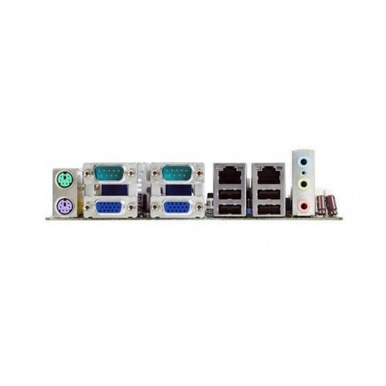
Page 15: Ordering Information
2U riser card with 3 PCI slot expansion IO View Accessories Part Number Description 1700003195 USB cable with two ports, 17.5 cm 1700002204 USB cable with two ports, 27 cm 1700002314 USB cable with four ports, 30.5 cm GMB-910 User Manual... -
Page 16: Layout Content List
7-pin header Suspend: Fast flash (ATX/AT) System On: on (ATX/AT) JFP3 Keyboard lock and power LED System Off: off (AT) System Off: slow flash (ATX) External speaker / JFP2 SATA HDD LED connector / SM Bus connector GMB-910 User Manual... -
Page 17: Table 1.4: Cmos1
Table 1.4: CMOS1 COMS1 Clear CMOS *Keep COMS data 1-2 closed Clear CMOS data 2-3 closed *Default setting Table 1.5: ATX/AT mode selector(JPSON1) JPSON1 AT(1-2) / ATX(2-3) AT Mode 1-2 closed *ATX Mode 2-3 closed *Default setting GMB-910 User Manual... -
Page 18: System Memory
This motherboard does not support memory modules made up of 128 MB chips or double-sided x16 memory modules. Make sure that the memory frequency matches the CPU FSB (Front Side Bus). Refer to the Memory frequency/CPU FSB synchronization table. GMB-910 User Manual... -
Page 19: Installing A Ddr2 Dimm
A DDR2 DIMM is keyed with a notch so that it fits in only one direc- tion. DO NOT force a DIMM into a socket to avoid damaging the DIMM. The DDR2 DIMM sockets do not support DDR DIMMs. DO NOT install DDR DIMMs to the DDR2 DIMM socket. GMB-910 User Manual... -
Page 20: Removing A Ddr2 Dimm
After installing the expansion card, configure it by adjusting the software settings. Turn on the system and change the necessary BIOS settings if any. Assign an IRQ to the card if needed. Refer to the tables on the next page. Install the software drivers for the expansion card. GMB-910 User Manual... -
Page 21: Standard Interrupt Assignments
*These IRQs are usually available for ISA or PCI device. 1.12.4 PCI Slots GMB-910 has one PCI slots. The PCI slots support cards such as a LAN card, SCSI card, USB card, and other cards that com- ply with PCI specifications. The figure shows a LAN card installed on a PCI slot. -
Page 22: Connectors
VGA port D-sub 15-pin, female VGA2 Table 1.8: LEDs ACT / LINK LED SPEED LED Status Description Status Description No link 10 Mbps connection Green Linked ORANGE 100 Mbps connection Blinking Data activity GREEN 1 Gbps connection GMB-910 User Manual... -
Page 23: System Fan Connector (Sysfan1)
These are not jumpers! DO NOT place jumper caps on the fan con- nectors. GMB-910 User Manual... -
Page 24: Serial Port Connector 34 (Com34) (Optional)
RRXD3 RRTS3_N TTXD3 CCTS3_N DDTR3_N RRI3_M DDSR4_N DDCD4_N RRXD4 RRTS4_N CCTS4_N TTXD4 DDTR4_N RRI4_N 1.13.4 Serial Port Connector 56 (COM56) (optional) DDCD5_N DDSR5_N RRXD5 RRTS5_N TTXD5 CCTS5_N DDTR5_N RRI5_M DDSR6_N DDCD6_N RRXD6 RRTS6_N CCTS6_N TTXD6 DDTR6_N RRI6_N GMB-910 User Manual... -
Page 25: Front Headphone Connector (Fpaud1)
I/O module cable to this connector. Note! For motherboards with the optional HD Audio feature, we recommend that you connect a high-definition front panel audio module to this con- nector to avail of the motherboard’s high definition audio capability. GMB-910 User Manual... -
Page 26: Front Panel Connector (Jfp1/Jfp2/Jfp3)
JFP2 SPEAKER JFP3 PWR_LED&KEY LOCK There are several external switches to monitor and control the GMB-910. 1.13.6.1 ATX Soft Power Switch (JFP1) If your computer case is equipped with an ATX power supply, you should connect the power on/off button on your computer case to JFP1 PIN1, 2. This connection enables you to turn your computer on and off. - Page 27 1.13.6.3 External Speaker (JFP2) JFP2 is a 4-pin connector for an external speaker. If there is no external speaker, the GMB-910 provides an onboard buzzer as an alternative. To enable the buzzer, set pins 5-7 as closed. JFP2 1.13.6.4 HDD LED Connector (JFP2) You can connect an LED to connector JFP2 to indicate when the HDD is active.
-
Page 28: Power Led And Keyboard Lock Connector
1-2 pin closed Connect 1-2 pin cable (On Back plane) with switch Jumper Setting System On System Status Fast flashes Fast flashes Fast flashes System Off Slow flashes JFP3 JFP3 pin.1 PWR_LED+ pin.2 pin.3 pin.4 #KB_LOCK pin.5 GMB-910 User Manual... -
Page 29: Usb 2.0 Connector (Usb56, Usb78)
These USB connectors comply with USB 2.0 specification that sup- ports up to 480 Mbps communication speed. USB56 USB78 Caution! Never connect a 1394 cable to the USB connectors. Doing so will dam- age the motherboard! Note! The USB module is purchased separately. GMB-910 User Manual... -
Page 30: Atx Power Connector (Eatxpwr1)
The system can become unstable and might experi- ence difficulty powering up if the power supply is inadequate. You must install a PSU with a higher power rating if you intend to install additional devices. GMB-910 User Manual... -
Page 31: 10Serial Ata Connector 1 & 2 (Sata1, Sata2)
Install the Windows® 2000 Service Pack 4 or the Windows® XP Service Pack1 before using Serial ATA. When using the connectors in Standard IDE mode, connect the pri- mary (boot) hard disk drive to the SATA1 connector. GMB-910 User Manual... - Page 32 GMB-910 User Manual...
-
Page 33: Chapter 2 Bios Operation
Chapter BIOS Operation... -
Page 34: Bios Introduction
CPUs from 386 through Pentium and AMD Geode, K7 and K8 (including multiple pro- cessor platforms), and VIA Eden C3 and C7 CPU. You can use Advantech’s utilities to select and install features to suit your designs for customer’s need. -
Page 35: Main Menu
Set Password Establish, change or disable password. Save & Exit Setup Save CMOS value settings to CMOS and exit BIOS setup. Exit Without Saving Abandon all CMOS value changes and exit BIOS setup. GMB-910 User Manual... -
Page 36: Standard Cmos Features
Extended Memory The POST of the BIOS will determine the amount of extended memory (above 1MB in CPU’s memory address map) installed in the system. Total Memory This item displays the total system memory size. GMB-910 User Manual... -
Page 37: Advanced Bios Features
This item enables users to switch A20 control by port 92 or not. Typematic Rate Setting This item enables users to set the two typematic controls items. This field controls the speed at – Typematic Rate (Chars/Sec) GMB-910 User Manual... - Page 38 APIC Mode [Enabled] This item allows user to enabled of disabled “Advanced Programmable Interrupt Controller”. APIC is implemented in the motherboard and must be supported by the operating system, and it extends the number of IRQ's available. GMB-910 User Manual...
-
Page 39: Advanced Chipset Features
This item allows the system BIOS to be cached to allow faster execution and better performance. Video BIOS Cacheable [Disabled] This item allows the video BIOS to be cached to allow faster execution and bet- ter performance. Memory Hole At 15 M-16 M [Disabled] GMB-910 User Manual... - Page 40 (DVMT).Bios provide three option to choose (DVMT, FIXED and Both). DVMT/FIXED Memory Size [128 MB] This item allows the user to adjust DVMT/FIXED graphics memory size. Boot Display [CRT1] This item allows the user to decide that display mode. GMB-910 User Manual...
-
Page 41: Integrated Peripherals
This item enables users to set the Onboard device status, includes enable USB, AC97, MC97 and LAN devices. Super IO Device This item enables users to set the Super IO device status, includes enable Floppy, COM, LPT, IR and control GPIO and Power fail status. GMB-910 User Manual... - Page 42 This item allows user to adjust serial port 4 of address. Onboard Serial Port 5 [4F0/IRQ10] This item allows user to adjust serial port 5 of address. Onboard Serial Port 6 [4F8/IRQ11] This item allows user to adjust serial port 6 of address. GMB-910 User Manual...
-
Page 43: Power Management Setup
The system shuts down with the exception of a refresh current to the system memory. Run VGA BIOS if S3 Resume [Auto] This item allows system to reinitialize VGA BIOS after system resume from ACPI S3 mode. GMB-910 User Manual... - Page 44 Secondary IDE 0 (1) becomes active. The choices are “Enabled” and “Dis- abled”. FDD, COM, LPT PORT [Disabled] When Enabled, the system will resume from suspend mode if the FDD, inter- face, COM port, or LPT port is active. The choices are “Enabled” and “Disabled”. GMB-910 User Manual...
- Page 45 The choices are “Enabled” and “Disabled”. Power on after power fail Use this to set up the system after power failure. The “Off” setting keeps the sys- tem powered off after power failure. The “On” setting boots up the system after failure. GMB-910 User Manual...
-
Page 46: Pnp/Pci Configurations
This is set to “Disabled” by default. Maximum Payload Size [4096] This allows you to set the maximum TLP payload size for PCI Express devices. The options are [128 bytes], [256 bytes], [512 bytes], [1024 bytes], [2048 bytes], and [4096 bytes]. GMB-910 User Manual... -
Page 47: Pc Health Status
This shows the voltage of VCORE, +1.5 V, +3.3 V, +5 V, VBAT (V), and 5 VSB (V). ACPI Shutdown Temperature The system will shut down automatically when the CPU temperature is over the selected setting. This function can prevent CPU damage caused by overheat- ing. GMB-910 User Manual... -
Page 48: Frequency/Voltage Control
When disabled, the BIOS will not monitor PCI slots. All clock signals will remain active even to unoccupied or inactive slots. Spread Spectrum [Disabled] This item enables users to set the spread spectrum modulation. CPU Clock It shows CPU Clock frequency 2.2.10 Set Password GMB-910 User Manual... - Page 49 Select Set Password again, and at the “Enter Password” prompt, please don’t enter anything; just press <Enter>. At the “Confirm Password” prompt, again, don’t type in anything; just press <Enter>. Select Save to CMOS and EXIT, type <Y>, then <Enter>. GMB-910 User Manual...
-
Page 50: Save & Exit Setup
Type "Y" will quit the BIOS Setup Utility and save user setup value to CMOS. Type "N" will return to BIOS Setup Utility. 2.2.12 Quit Without Saving Note! Type "Y" will quit the BIOS Setup Utility without saving to CMOS. Type "N" will return to BIOS Setup Utility. GMB-910 User Manual... -
Page 51: Chipset Software Install Utility
Chapter Chipset Software Install Utility... -
Page 52: Before You Begin
The device drivers for the GMB-910 board are located on the software installation CD. The auto-run function of the driver CD will guide and link you to the utilities and device drivers under a Windows system. -
Page 53: Windows Xp Driver Setup
Insert the driver CD into your system's CD-ROM drive. You can see the driver folders items. Move the mouse cursor over the folder "INF". In INF folder, you can click "setup.exe" to complete the implement of the driver. GMB-910 User Manual... - Page 54 GMB-910 User Manual...
-
Page 55: Vga Setup
Chapter VGA Setup... -
Page 56: Introduction
The following installation procedure is for Windows XP. For other operating systems, please do a manual installation. Move the mouse cursor over the folder "Drv_VGA". In Drv_VGA folder, you can click Installshield Wizard under Windows\win2k_xp142550 to automatic complete the implement of the driver. GMB-910 User Manual... - Page 57 GMB-910 User Manual...
- Page 58 GMB-910 User Manual...
-
Page 59: Lan Configuration
Chapter LAN Configuration... -
Page 60: Introduction
Introduction The GMB-910 features dual Gigabit Ethernet network interface. With the Realtek RTL8111C GbE controller designed-in, GMB-910 implements the PCI Express host interface (PCI-E X1) in LAN connection with the maximum throughput of 2Gbps for heavy-duty industrial network application. Features... - Page 61 Based on different OS, choose proper LAN driver to install. GMB-910 User Manual...
- Page 62 GMB-910 User Manual...
-
Page 63: Appendix A Programming The Watchdog
Appendix Programming the Watchdog... -
Page 64: Programming The Watchdog Timer
Programming the Watchdog Timer The GMB-910's watchdog timer can be used to monitor system software operation and take corrective action if the software fails to function after the programmed period. This section describes the operation of the watchdog timer and how to pro- gram it. - Page 65 GMB-910 User Manual...
-
Page 66: Table A.1: Watchdog Timer Registers
Bit 5: Write 1 to generate a timeout sig- nal immediately and automatically return to 0. [default=0] Bit 4: Read status of watchdog timer, 1 means timer is ""time out""." AA (hex) Write this address to I/O port 2E (hex) to lock the watchdog timer.2. GMB-910 User Manual... -
Page 67: Example Program
Mov al,10 Out dx,al ;----------------------------------------------------------- Dec dx ; lock W83627DHG-A Mov al,0aah Out dx,al 2. Enable watchdog timer and set 5 minutes as timeout interval ;----------------------------------------------------------- Mov dx,2eh ; unlock W83627DHG-A Mov al,87h Out dx,al Out dx,al GMB-910 User Manual... - Page 68 3. Enable watchdog timer to be reset by mouse ;----------------------------------------------------------- Mov dx,2eh ; unlock W83627DHG-A Mov al,87h Out dx,al Out dx,al ;----------------------------------------------------------- Mov al,07h ; Select registers of watchdog timer Out dx,al Inc dx Mov al,08h Out dx,al ;----------------------------------------------------------- GMB-910 User Manual...
- Page 69 Dec dx ; Enable the function of watchdog timer Mov al,30h Out dx,al Inc dx Mov al,01h Out dx,al ;----------------------------------------------------------- Dec dx ; Enable watchdog timer to be strobed reset by keyboard Mov al,0f7h Out dx,al Inc dx In al,dx Or al,40h Out dx,al GMB-910 User Manual...
- Page 70 Dec dx ; Generate a time-out signal Mov al,0f7h Out dx,al ;Write 1 to bit 5 of F7 register Inc dx In al,dx Or al,20h Out dx,al ;----------------------------------------------------------- Dec dx ; lock W83627DHG-A Mov al,0aah Out dx,al GMB-910 User Manual...
-
Page 71: Appendix B Pin Assignments
Appendix Pin Assignments... -
Page 72: Usb Connector (Usb56,Usb78)
+5 V LP5- LP5+ LP5+ LP5- VGA Connector (VGA1, VGA2) Table B.2: VGA Connector (VGA1, VGA2) Signal Signal GREEN BLUE SDAT H-SYNC V-SYNC SCLK RS-232 Serial Port (COM1, COM2) Table B.3: Rs-232 Serial Port (COM1, COM2) Signal GMB-910 User Manual... - Page 73 Table B.4: RS-232 Serial Port (COM34) Signal Signal DDCD3_N DDSR3_N RRXD3 RRTS3_N TTXD3 CCTS3_N DDTR3_N RRI3_N DDCD4_N DDSR4_N RRXD4 RRTS4_N TTXD4 CCTS4_N DDTR4_N RRI4_N Table B.5: RS-232 Serial Port (COM56) Signal Signal DDCD5_N DDSR5_N RRXD5 RRTS5_N TTXD5 CCTS5_N DDTR5_N RRI5_N GMB-910 User Manual...
-
Page 74: Ps/2 Keyboard/ Mouse Connnector (Kbms1)
You can use an LED to indicate when the single board computer is on. Pin 1 of JFP3 supplies the LED's power, and Pin 3 is the ground. Table B.7: Power LED and Keylock Connector (JFP3) Function LED power (+5 V) GMB-910 User Manual... -
Page 75: External Speaker Connector (Jfp2/ Speaker)
The single board computer has its own buzzer. You can also connect it to the external speaker on your computer chassis. Table B.8: External Speaker Connector (JFP2/SPEAKER) Signal Signal SPK+ HDDLED+ HDDLED- SPK_IN SMB_DAATA SPK- SMB_CLK Reset Connector (JFP1/ RESET) Table B.9: Reset Connector (JFP1/ RESET) Signal PWR_BTN# RESET GMB-910 User Manual... -
Page 76: Hdd Led Connector (Jfp2/ Hddled)
Table B.11: ATX Soft Power Switch (JFP1/ PWR_SW) Signal PWR-BTN B.11 AC-97 Audio Interface (FPAUD1) Table B.12: AC-97 Audio Interface (FPAUD1) 1 MIC-IN 2 GND 3 MIC_VCC 4 VCC 5 LRR 6 LOUT_R 7 JDO 8 NC 9 LRL 10 LOUT_L GMB-910 User Manual... -
Page 77: Sm Bus Connector (Jfp2)
On-board hardware monitor 2F8-2FF Serial port 2 300-31F Prototype card 360-36F Reserved 380-38F SDLCm bisynchronous 2 3A0-3AF Bisynchronous 1 3C0-3CF Reserved 3D0-3DF Color/graphics monitor adapter 3F0-3F7 Diskette controller 3F8-3FF Serial port 1 4E0~55F General Purpose Decoder (Serial Port 3~6) GMB-910 User Manual... -
Page 78: Dma Channel Assignments
1st MB Memory Map Table B.17: 1st MB Memory Map Addr. range (Hex) Device E0000h - FFFFFh BIOS CC000h - DFFFFh Unused C0000h - CBFFFh VGA BIOS A0000h - BFFFFh Video Memory 00000h - 9FFFFh Base memory GMB-910 User Manual... -
Page 79: Pci Bus Map
B.17 PCI Bus Map Table B.18: PCI Bus Map Function Signals Device ID INT# pin PCI slot 1 AD31 INT B, C, D, A SNT0 REQ0 GMB-910 User Manual... - Page 80 No part of this publication may be reproduced in any form or by any means, electronic, photocopying, recording or otherwise, without prior written permis- sion of the publisher. All brand and product names are trademarks or registered trademarks of their respective companies. © Advantech Co., Ltd. 2008...
Need help?
Do you have a question about the GMB-910 and is the answer not in the manual?
Questions and answers