
Related Manuals for Advantech AOM-2721


Summary of Contents for Advantech AOM-2721
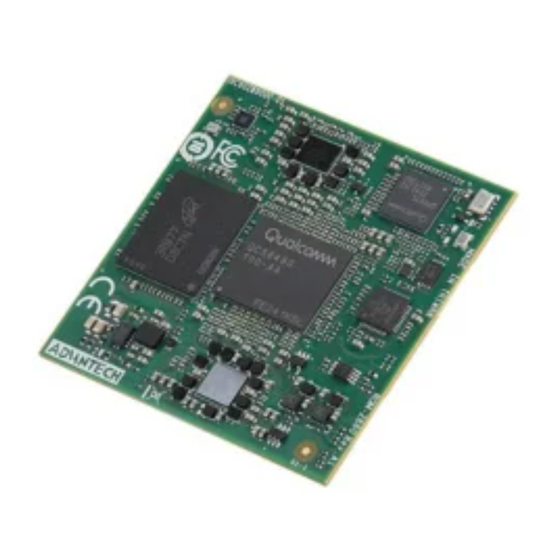
- Page 1 User Manual AOM-2721 AOM-DK2721 Qualcomm QCS6490 2.7GHz Gold Plus 8 cores OSM 1.1 Computer-on-Module...
-
Page 2: Product Warranty (2 Years)
No part of this manual may be reproduced, copied, translated or transmitted in any form or by any means without the prior written permission of Advantech Co., Ltd. Information provided in this manual is intended to be accurate and reliable. How- ever, Advantech Co., Ltd. -
Page 3: Ordering Information
FCC Class B Note: This equipment has been tested and found to comply with the limits for a Class B digital device, pursuant to part 15 of the FCC Rules. These limits are designed to provide reasonable protection against harmful interference in a residential installa- tion. - Page 4 Part No. Description ROM-ED92 Carrier board of AOM-2721 96PSA-A36W12R1-3 ADP A/D 100-240V 36W 12V C6 LOCK DC JACK 62368 1700008921 Power Cord 3P PSE 183 cm (72 in) 1700021565-01 Debug cable 1x4P-1.25/D-SUB 9P(F) ROM-EG51 Audio Codec board 1700031429-01 Line out cable...
- Page 5 The equipment has been dropped and damaged. ◼ The equipment has obvious signs of breakage. DISCLAIMER: This set of instructions is given according to IEC 704-1. Advantech disclaims all responsibility for the accuracy of any statements contained herein. Safety Precaution - Static Electricity Follow these simple precautions to protect yourself from harm and the products from damage.
-
Page 7: Table Of Contents
Contents Chapter General Introduction ......Introduction ......................2 Product Features ....................2 Table 1.1: Product Features ............... 2 Mechanical Specifications ................. 3 1.3.1 Electrical Specifications ................ 3 1.3.2 Environmental Specifications ............... 3 Chapter H/W Installation ........Board Dimensions ....................6 Block Diagram ..................... - Page 8 Introduction ......................28 4.1.1 Device Tree Source File Select for AOM-2721 ......28 4.1.2 Module ....................28 Chapter System Recovery ......... System Recovery ....................30 5.1.1 Recovery by UUU Tool ............... 30 Chapter Advantech Services ......RISC Design-In Services ................. 32 Contact Information ..................
-
Page 9: Chapter 1 General Introduction
Chapter General Introduction This chapter details background information on the AOM-2721. Sections include: ◼ Introduction ◼ Specifications... -
Page 10: Introduction
633 graphics engine. It provides PCIe, USB 3.2, Giga Ethernet, MIPI-CSI, SPI, GPIO, and HDMI, DP, 2ch. LVDS display for embedded applications. AOM-2721 is paired with Advantech OSM carrier board for faster end product peripheral integration and time-to-market. The reference schematics and layout checklists documentations for carrier board development will be provided along with Windows 11, Ubuntu, test utilities, hardware design utilities and reference drivers. - Page 11 Certifications CE/FCC Class B...
-
Page 12: Mechanical Specifications
1.3.2 Environmental Specifications ◼ Operating Temperature: -20 ~ 70 °C ◼ Operating Humidity: 5 ~ 95% relative humidity, non-condensing ◼ Storage Temperature: -40 ~ 85 °C/-40~185 °F ◼ Storage Humidity: 60 °C/140 °F @ 95% RH non-condensing AOM-2721 User Manual... -
Page 15: Chapter 2 H/W Installation
Chapter H/W Installation This chapter details mechanical and connector information. Sections include: ◼ Mechanical Drawing ◼ Pin Define ◼ Quick Start Guide... -
Page 16: Board Dimensions
AOM-2721 Board Dimensions Block Diagram... -
Page 17: Pin Define
Pin Define Power- GND and Contact Name Contact Acronym AOM-2721 Control Y17, Y8, Y9, Y10, Y11, Y25, Y26, Y27, VCC_IN_5V Y28, AE4, AF4, AG4, +VCC_IN_5V AH3, AH4, AJ3, AJ4, D18, E15, E21, F16, F20, J16, J20, L18, M16, M20, P18,... - Page 18 PWR_BTN# PHONE_ON# JTAG Contact Name Contact Acronym AOM-2721 JTAG_TCK(SWCLK) QCM_JTAG_TCK JTAG_TMS(SWDIO) QCM_JTAG_TMS JTAG_TDI QCM_JTAG_TDI JTAG_TDO(SWO) QCM_JTAG_TDO JTAG_nTRST QCM_JTAG_TRST# UART Contact Name Contact Acronym AOM-2721 UART_A_RX UART_A_RX UART_A_TX UART_A_TX UART_A_RTS UART_A_RTS# UART_A_CTS UART_A_CTS# UART_B_RX UART_B_RX UART_B_TX UART_B_TX UART_B_RTS UART_B_RTS# UART_B_CTS UART_B_CTS#...
- Page 19 ETH_B_(R)(G)MII_RX_ER ETH_B_(R)(G)MII_RX_DV(_ER) L1 ETH_B_RX_CTL ETH_B_(R)(G)MII_RX_CLK ETH_B_RXC ETH_B_SDP ETHB_MDIO ETH_B_MDIO ETHB_MDC ETH_B_MDC GPIO Contact Name Contact Acronym AOM-2721 GPIO_A_0 QCS_GPIO_14 GPIO_A_1 QCS_GPIO_15 GPIO_A_2 QCS_GPIO_16 GPIO_A_3 QCS_GPIO_17 GPIO_A_4 QCS_GPIO_18 GPIO_A_5 QCS_GPIO_19 GPIO_A_6/SPI_A_CS1# SPI0_CS3# GPIO_A_7/SPI_B_CS1# SPI1_CS3# GPIO_B_0 QCS_GPIO_80 GPIO_B_1 QCS_GPIO_83 GPIO_B_2 QCS_GPIO_93 GPIO_B_3...
- Page 20 SDIO Contact Name Contact Acronym AOM-2721 VENDOR_DEFINED_3 SDC1_RCLK SDIO_A_PWR_EN QCM_RESOUT# SDIO_A_IOPWR +VREG_L6C_2P96 Contact Name Contact Acronym AOM-2721 UFS_TX0_P AC28 UFS_L0_TX+ UFS_TX0_N AC29 UFS_L0_TX- UFS_TX1_P AB29 UFS_L1_TX+ UFS_TX1_N AB30 UFS_L1_TX- UFS_RX0_P AC31 UFS_L0_RX+ UFS_RX0_N AC32 UFS_L0_RX- UFS_RX1_P AB32 UFS_L1_RX+ UFS_RX1_N AB33...
- Page 21 SPI_C Contact Name Contact Acronym AOM-2721 SPI_C_CS0# SPI2_CS0# SPI_C_CS1# / GPIO_D_7 SPI2_CS1# SPI_C_SCK SPI2_SCLK Contact Name Contact Acronym AOM-2721 I2S_A_DATA_IN LPI_QUA_MI2S_DATA0 I2S_A_DATA_OUT LPI_QUA_MI2S_DATA1 I2S_B_DATA_IN LPI_QUA_MI2S_DATA2 I2S_B_DATA_OUT LPI_QUA_MI2S_DATA3 I2S_MCLK I2S_MCLK I2S_LRCLK LPI_QUA_MI2S_WS I2S_BITCLK LPI_QUA_MI2S_SCK Contact Name Contact Acronym AOM-2721 CAN_A_TX AC17...
- Page 22 USB0_SS_RX0- USB_C_SSRX_N USB0_SS_RX0+ USB_C_SSTX_P DP_HOT_PLUG_DETECT VENDOR_DEFINED_2 USB0_DP_AUX_CONN- VENDOR_DEFINED_5 USB0_DP_AUX_CONN+ VENDOR_DEFINED_4 Contact Name Contact Acronym AOM-2721 I2C_A_SCL AA15 I2C_A_SCL I2C_A_SDA AA16 I2C_A_SDA I2C_B_SCL AA20 I2C_B_SCL I2C_B_SDA AA21 I2C_B_SDA Contact Contact Name AOM-2721 Acronym eDP_A_LANE0_P EDP0_TX0_FLT+ eDP_A_LANE0_N EDP0_TX0_FLT- eDP_A_LANE1_P EDP0_TX1_FLT+ eDP_A_LANE1_N EDP0_TX1_FLT-...
- Page 23 MIPI DSI Contact Name Contact Acronym AOM-2721 DISP_BL_PWM /PWM_0 E18 MIPI CSI3 Contact Name Contact Acronym AOM-2721 CSI_DATA0_N CSI3_D0- CSI_DATA0_P CSI3_D0+ CSI_DATA1_N CSI3_D1- CSI_DATA1_P CSI3_D1+ CSI_DATA2_N CSI3_D2- CSI_DATA2_P CSI3_D2+ CSI_DATA3_N CSI3_D3- CSI_DATA3_P CSI3_D3+ CSI_CLOCK_N CSI3_CLK- CSI_CLOCK_P CSI3_CLK+ CAM_MCK CAM_MCLK3 I2C_CAM_SDA / CSI_TX_N...
- Page 24 PCIe_B Contact Name Contact Acronym AOM-2721 PCIe_B_HSI0_N QPS_DS1_PCIE1_RX0- PCIe_B_HSO0_P QPS_DS1_PCIE1_TX0+ PCIe_B_HSO0_N QPS_DS1_PCIE1_TX0- PCIe_B_PERST# QPS_DS1_PCIE1_RESET# RESERVED_8 QPS_DS1_PCIE1_REFCLK+ RESERVED_9 QPS_DS1_PCIE1_REFCLK- RESERVED_10 PCIE_B_CLKREQ# PCIe_C Contact Name Contact Acronym AOM-2721 PCIe_C_HSO0_N AR33 QPS_DS0_PCIE0_TX0- PCIe_C_HSO0_P AR34 QPS_DS0_PCIE0_TX0+ PCIe_C_HSO1_N AN34 QPS_DS0_PCIE0_TX1- PCIe_C_HSO1_P AM34 QPS_DS0_PCIE0_TX1+ PCIe_C_HSO2_N AK34...
-
Page 25: Quick Start Guide
Quick Start Guide 2.4.1 I/O Description of AOM-DK2721 AOM-DK2721 is an evaluation board for AOM-2721. Please see the I/O description of AOM-DK2721 below. - Page 26 2.4.2 Switch Setting for AOM-DK2721...
-
Page 28: Debug Port Connection And Setting
1700021565-01 Debug cable 1x4P-1.25/D-SUB 9P(F) 1. AOM-2721 can communicate with a host server using serial cables. Common serial communication programs such as HyperTerminal, Tera Term or PuTTY can be used in such applications. The example demonstrated below describes the serial terminal setup using Tera Term on a Windows host: Open Tera Term on your Windows PC, and select the settings as shown in figure. - Page 30 Connect a Display: AOM-2721 has three display options: one is HDMI, DP and the other is 2 ch. LVDS. The default display is HDMI. LVDS DP & DP&HDM...
- Page 31 Connect the Power Source: AOM-2721’s power input is 12VDC. The power interface’s location is DCIN1. Please choose a suitable adapter and power cord to connect the board (please refer to P/Ns on datasheet and Optional Accessories of this manual) as shown in Figure 2.25.
- Page 32 3. Power on and login Follow these steps to connect the device to the host machine through UART. • Connect the debug cable to the "COME Debug" and connect the device to the host machine • Connect the 12V power adapter to "12V DC-IN" •...
-
Page 33: Chapter 3 Software Functionality
Chapter Software Functionality This chapter details the software functions on the AOM-2721. -
Page 34: Display
Display 3.1.1 LVDS If you need the LVDS + DP output, you can use the following tool to change it. # /tools/display/emmcChangeToLVDS.sh # /tools/display/ufsChangeToLVDS.sh It can support the following LVDS panels: 7" AUO G070VW01 V1 single channel (VDD:3.3V, Backlight Power:12V) •... -
Page 35: Audio
• Manually Switch to 720P@60 # echo 1280 720 60 > /sys/bus/i2c/drivers/lt9611/2-002b/edid_mode # systemctl restart init_display.service • Manually Switch to 480P@60 # echo 720 480 60 > /sys/bus/i2c/drivers/lt9611/2-002b/edid_mode # systemctl restart init_display.service 3.1.3 It can support the maximum resolution is 4K@30. Audio Connect the ROM-EG51 to the ROM-ED92 I2S_CN1 and boot up the device. -
Page 36: Spi Flash
3.3.1 EMMC eMMC: /dev/mmcblk0 # dd if=/dev/urandom of=data bs=1 count=1024 # dd if=/dev/mmcblk0 of=backup bs=1 count=1024 skip=4096 # dd if=data of=/dev/mmcblk0 bs=1 seek=4096 # dd if=/dev/mmcblk0 of=data1 bs=1 count=1024 skip=4096 # diff data data1 # dd if=backup of=/dev/mmcblk0 bs=1 seek=4096 3.3.2 SD Card Connect the Micro SD card to the ROM-ED92 SD_CARD1. -
Page 37: Serial Port (Com A/C)
Serial ports 3.4.1 RS232 Loopback • UART 2 (Default RS-232 function): ROM-ED92 COMB1 • UART 3: ROM-ED92 COMC1 • UART 4: ROM-ED92 COMD1 UART 2 # stty -F /dev/ttyHS9 -echo -onlcr 115200 raw # cat /dev/ttyHS9 & # echo "Serial Port Test" > /dev/ttyHS9 UART 3 # stty -F /dev/ttyHS10 -echo -onlcr 115200 raw # cat /dev/ttyHS10 &... - Page 38 UART 2 # echo 587 > /sys/class/gpio/export (UART MODE1) # echo 588 > /sys/class/gpio/export (UART MODE0) # echo out > /sys/class/gpio/gpio587/direction # echo out > /sys/class/gpio/gpio588/direction # echo 1 > /sys/class/gpio/gpio587/value # echo 0 > /sys/class/gpio/gpio588/value # stty -F /dev/ttyHS2 speed 115200 ignbrk -brkint -icrnl -imaxbel -opost -onlcr -isig -icanon -iexten -echo -echoe -echok -echoctl -echoke # cat /dev/ttyHS2 &...
-
Page 40: Ethernet
Ethernet Check Ethernet # ifconfig enP1p5s0f0 Link encap:Ethernet HWaddr EE:A9:36:72:A7:B9 inet addr:172.22.12.138 Bcast:172.22.15.255 Mask:255.255.252.0 inet6 addr: fe80::2009:4a63:5a32:d2ab/64 Scope:Link inet6 addr: fe80::eca9:36ff:fe72:a7b9/64 Scope:Link UP BROADCAST RUNNING MULTICAST MTU:1500 Metric:1 RX packets:118 errors:0 dropped:10 overruns:0 frame:0 TX packets:37 errors:0 dropped:0 overruns:0 carrier:0 collisions:0 txqueuelen:1000 RX bytes:27625 (26.9... - Page 41 # ethtool -s enP1p5s0f1 speed 100 duplex full 1000M Speed Setting # ethtool -s enP1p5s0f0 speed 1000 duplex full # ethtool -s enP1p5s0f1 speed 1000 duplex full ⚫ Micro USB: ROM-ED92 USB0 ⚫ USB 2.0/3.0 Type A: ROM-ED92 USB1 Micro USB Micro USB is only for the EDL download.
-
Page 42: External Rtc
0x57: EEPROM of CH7513A-BFI (eDP to LVDS bridge) For the 0x23 and 0x57: • # i2cdetect -y -r 0 • • -- -- -- -- -- -- -- -- -- -- -- -- -- • 10: -- -- -- -- -- -- -- -- -- -- -- -- -- -- -- -- •... -
Page 43: Camera
Set one incorrect time, then read time from RTC to verify # date 010100002000 && hwclock -r && date Sat Jan 00:00:00 UTC 2000 2024-03-20 10:47:33.749407+00:00 Sat Jan 00:00:00 UTC 2000 Restore the RTC time to system time # hwclock -s && date Wed Mar 10:49:03 UTC 2024... - Page 44 MIPI CSI1 and MIPI CSI2 Multi Camera Preview # source /opt/qcom/qirp-sdk/qirp-setup.sh # export XDG_RUNTIME_DIR=/dev/socket/weston && export WAYLAND_DISPLAY=wayland-1 && gst-launch-1.0 -e qtiqmmfsrc camera=0 name=camsrc ! video/x-raw,format=NV12,width=3840,height=2160,framerate=30/1 ! waylandsink x=0 y=0 & # export XDG_RUNTIME_DIR=//dev/socket/weston && export WAYLAND_DISPLAY=wayland-1 && gst-launch-1.0 -e qtiqmmfsrc camera=1 name=camsrc ! video/x-raw,format=NV12,width=3840,height=2160,framerate=30/1 ! waylandsink x=960 y=0 &...
- Page 46 3.12 M.2 Key E Wi-Fi / BT (EWM-W170BQ) 3.12.1 WIFI Connection # lspci 0000:00:00.0 PCI bridge: Qualcomm Device 010b 0000:01:00.0 Network controller: Qualcomm QCNFA765 Wireless Network Adapter (rev 01) # ifconfig wlp1s0 wlp1s0 Link encap:Ethernet HWaddr 00:0E:8E:BF:DE:0D UP BROADCAST MULTICAST MTU:1500 Metric:1 RX packets:0 errors:0 dropped:0 overruns:0 frame:0...
- Page 47 TX bytes:579 acl:0 sco:0 commands:59 errors:0 # hciconfig hci0 up # bluetoothctl # discoverable on # pairable on # scan on [NEW] FC:18:3C:8D:75:F4 myphone # scan off # pair FC:18:3C:8D:75:F4 # connect FC:18:3C:8D:75:F4 3.13 M.2 Key B Support AIW-356 5G module. Need to insert the nano SIM card.
-
Page 48: Power Button
• # microcom -t 15000 -s 115200 /dev/ttyUSB2 • at+gtusbmode=30 • • 2. Use the MBIM to connect the internet: • # chmod u+w /sys/bus/usb-serial/drivers/option1/new_id • # echo "2cb7 0111" > /sys/bus/usb-serial/drivers/option1/new_id • # mbimcli -d /dev/cdc-wdm0 -p --query-connection-state • # mbimcli -d /dev/cdc-wdm0 -p --query-subscriber-ready-status •... -
Page 49: Embedded Os
Chapter Embedded O.S This chapter details instructions for building Linux systems... -
Page 50: Introduction
Advantech’s AOM-2721 comes preloaded with Ubuntu 20.04 based embedded O.S., It contains all the system-required shell commands and drivers needed to operate the platform. We do not offer IDE developing environment on AOM-2721 BSP. Users can evaluate and develop their device using the Ubuntu 20.04 LTS environment. - Page 51 Chapter System Recovery This chapter details system recov- ery procedures for a damaged Linux OS.
-
Page 52: Chapter 5 System Recovery
System Recovery Using windows PCAT or Qualcomm Download (QDL) tool to flash software images to the device. Emergency download (EDL) mode • Connect the Micro USB (EDL) to your linux host computer. • SW1 ( 1-off, 2-on ) : EMMC Boot •... - Page 53 • Connect the adapter and power on the device Windows PCAT Tool Prepare Download the Qualcomm Software Center: https://softwarecenter.qualcomm.com/#/catalog/item/Qualcomm_Software_Center Open the Qualcomm Software Center Search "PCAT" in the search bar Click Qualcomm® Product Configuration Assistant Tool Select Qualcomm® Product Configuration Assistant Tool versio : 2.33.2.119 Install Qualcomm®...
- Page 54 Search "QUTS" in the search bar Click the Qualcomm® Unified Tools Services Select Qualcomm® Unified Tools Services version : 1.75.2.9 Install Qualcomm® Unified Tools Services 1.75.2.9 11. You will find the new application in your Windows system . 12. Unzip the UFS File and eMMC File For example : 2860A1AIM38LIV11030_2024-11-18_ufs.tgz 2860A1AIM38LIV11030_2024-11-18_emmc.tgz...
- Page 55 2. Add the prog_firehose_ddr.elf and provision_ufs31.xml in UFS folder. 3. Then press "OK" , it will start to do USF Provision. When the Provision finished , you can see the result in message window. Flash UFS Change the SW1 and SW2: Flash UFS: The SW1 switch to 1-on, 2-on Forced Recovery: The SW2 switch to 1-on, 2-on Turn on the power...
- Page 56 Select "Qualcomm HS-USB QDLoader 9008 (COM6) Click " Connect " device When you connected successfully , it will show "green word" - Qualcomm HS-USB QDLoader 9008 (COM 6) Select UFS Folder in PCAT Tool , the Tool will help load Files automatically and Select "MEMORY_TYPE_UFS"...
- Page 57 lick " Download" FS Download Status FS Donwload compeleted Flash EMMC...
- Page 58 urn off the Power hange the SW1 and SW2 lash eMMC: The SW1 switch to 1-off, 2-on orced Recovery: The SW2 switch to 1-on, 2-on urn on the power Make sure the device connection status. the device disconnect with PCAT Tool , please connect it again. elect EMMC Folder.
- Page 59 Make sure the setting ,then press " Download " button. MMC downlaoad status...
- Page 60 MMC Donwload compeleted Qualcomm Download (QDL) Tool One-time Prerequisite To set the udev USB rule with the Qualcomm manufacturing vendor ID 05c6: /etc/udev/rules.d $ sudo vi 51-qcom-usb.rules # add the following SUBSYSTEMS=="usb", ATTRS{idVendor}=="05c6", ATTRS{idProduct}=="9008", MODE="0666", GROUP="plugdev" $ sudo systemctl restart udev Use the QDL to flash images (UFS only now) nsure the QDL mode $ lsusb...
- Page 61 READ64 image: offset: 0x0 length: 0x40 READ64 image: offset: 0x40 length: 0x3f0 READ64 image: offset: 0x1000 length: 0x1000 READ64 image: offset: 0x2000 length: 0x260 READ64 image: offset: 0x3000 length: 0x1000 READ64 image: offset: 0x4000 length: 0x1000 Update Primary Header with CRC of Primary Header. LOG: INFO: Calling handler patch Zero Out Header CRC...
-
Page 62: Chapter 6 Advantech Services
Chapter Advantech Services This chapter outlines Advantech's Design-In services, technical sup- port, and warranty policy for ROM- 2820. -
Page 64: Risc Design-In Services
Comprehensive document support Design Assistance Service Advantech provides a checklist for engineers to check their schematics and review services based on customer carrier board schematics. These services prevent design errors before they occur. This saves time and reduces costs associated with developing carrier boards. - Page 65 R&D costs and hardware investment. By virtue of a cooperative relationship with leading original manufacturers of CPUs and chipsets - such as ARM, TI, and NXP - Advantech helps solve communication and technical support difficulties. This can reduce the uncertainties in product devel- opment.
- Page 66 I/O and perfor- mance. Advantech also offers software evaluation and peripheral module recommen- dations (such as WiFi, 3G, BT). At this stage, Advantech seeks to resolve customer concerns. Product evaluation with a focus on performance and specification is vital during the planning period.
-
Page 67: Contact Information
Japan (Toll Free) 0800-500-1055 080-363-9494 Korea (Toll Free) 080-363-9495 Taiwan (Toll Free) 0800-777-111 Russia (Toll Free) 8-800-555-01-50 Alternatively, you can contact the Advantech service team via our website. http://www.advantech.com.tw/contact/default.aspx?page=contact_form2&sub- ject=Technical+Support Our technical support engineers will provide a quick response to your queries... -
Page 68: Technical Support And Assistance
The DOA cross-shipment excludes any shipping damage, customized and/or build- to-order products. For products that are not DOA, the return fee to an authorized Advantech repair facil- ity will be at the customer's expense. The shipping fee for reconstructed products from Advantech back to the customer will be at Advantech's expense. -
Page 69: Repair Process
"Attn. RMA Service Department". All products must be returned in properly packed ESD material or anti-static bags. Advantech reserves the right to return unrepaired items at the customer's cost if inap- propriately packed. Door-to-Door transportation, such as speed post, is recommended for delivery. Oth- erwise, the sender should bear additional charges such as clearance fees if air cargo shipment methods are used. - Page 70 The product is sent for updates, upgrades, or tests at the request of the cus- tomer who is without warranty. If a product has been repaired by Advantech, and within three months after such a repair the product requires another repair for the same problem, Advantech will con- duct the repair free of charge.
- Page 71 Chapter 6 Advantech Services...
- Page 72 No part of this publication may be reproduced in any form or by any means, electronic, photocopying, recording, or otherwise, without prior written permis- sion from the publisher. All brand and product names are trademarks or registered trademarks of their respective companies. © Advantech Co., Ltd. 2024...
Need help?
Do you have a question about the AOM-2721 and is the answer not in the manual?
Questions and answers