Table of Contents
Advertisement
Quick Links
Advertisement
Table of Contents

Related Manuals for d&b audiotechnik 12S


Summary of Contents for d&b audiotechnik 12S
- Page 1 12S/12S-D Manual (1.1 EN)
- Page 2 General information 12S/12S-D Manual Version: 1.1 EN, 01/2011, D2612.EN .01 Copyright © 2011 by d&b audiotechnik GmbH; all rights reserved. Keep this manual with the product or in a safe place so that it is available for future reference. When reselling this product, hand over this manual to the new customer.
-
Page 3: Table Of Contents
2.1. Product description............5 2.2. Connections..............5 2.3. Operation..............7 2.3.1. Controller settings............ 7 2.4. Dispersion characteristics..........8 2.5. Technical specifications..........10 Manufacturer's Declarations........11 3.1. EU conformity of loudspeakers (CE symbol)... 11 3.2. WEEE Declaration (Disposal)........11 d&b 12S/12S-D Manual (1.1 EN) -
Page 4: Safety Precautions
Generally speaking, a distance of 0.5 m (1.5 ft) from magnetic data carriers (floppy disks, audio and video tapes, bank cards, etc.) is sufficient; a distance of more than 1 m (3 ft) may be necessary with computer and video monitors. d&b 12S/12S-D Manual (1.1 EN) -
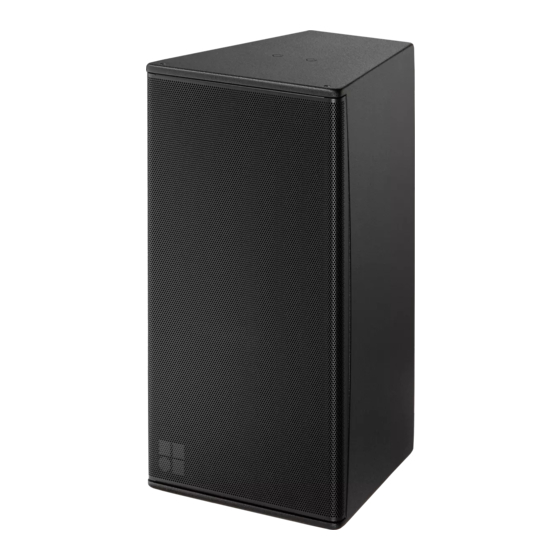
Page 5: S/12S-D Loudspeaker
Rigging components The 12S rear panels incorporate two M8 threaded inserts to accept the Z5406 12S Flying bracket or the Z5402 Wall mount M or Z5403 Wall mount L. Top and bottom panels of the cabinets are each equipped with a... - Page 6 Fixed cable connection The 12S and 12S-D loudspeakers are each supplied with a cover plate [1] and a rubber grommet feed through [2]. For indoor operation, these items can be used to hide the connector panel, if required. For unprotected outdoor operation, the connector panel must be covered, i.e.
-
Page 7: Operation
"Mix TOP/SUB" mode. For combinations with active subwoofers fed by a single 4-wire cable "Mix TOP/SUB" mode must be selected. Up to a total of two 12S or 12S-D loudspeakers can be driven by each channel of the D6 or D12 amplifiers. 2.3.1. Controller settings For acoustic adjustment the functions CUT, HFA and CPL can be selected. -
Page 8: Dispersion Characteristics
(isobars) at –6 dB and –12 dB. vertical setup Fig. 8: Isobar diagram horizontal Fig. 9: Isobar diagram vertical horizontal setup, horn rotated Fig. 10: Isobar diagram horizontal Fig. 11: Isobar diagram vertical d&b 12S/12S-D Manual (1.1 EN) - Page 9 – Fold down the grill into the recess on the other side and make sure it properly fits on all sides. – Insert the 4 torx screws and tighten them until they fit precisely into the counter sunk holes. Fig. 16: Altering the HF dispersion d&b 12S/12S-D Manual (1.1 EN)
-
Page 10: Technical Specifications
130 dB/133 dB (SPLmax peak, pink noise test signal with crest factor of 4) Input level (100 dB-SPL/1 m) –14 dBu Fig. 17: 12S frequency response, standard and CUT modes 12S/12S-D loudspeaker Nominal impedance 8 ohms Power handling capacity (RMS/peak 10 ms) 300/1600 W Nominal dispersion angle (hor. -
Page 11: Manufacturer's Declarations
Please dispose of this product according to the respective national regulations or contractual agreements. If there are any further questions concerning the disposal of this product, please contact d&b audiotechnik. d&b 12S/12S-D Manual (1.1 EN) - Page 12 www.dbaudio.com...
Need help?
Do you have a question about the 12S and is the answer not in the manual?
Questions and answers