State Water Heaters Ultra Forcce SUF 60 120 Installation & Operation Manual
Commercial gas water heater
Hide thumbs
Also See for Ultra Forcce SUF 60 120:
- Installation, user and service manual (97 pages) ,
- Instruction manual (80 pages) ,
- Service handbook (54 pages)
Table of Contents
Advertisement
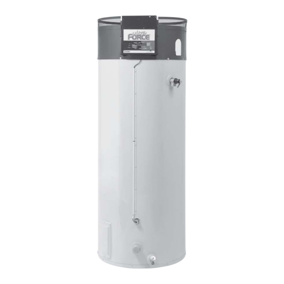
ULTRA FORCE
COMMERCIAL GAS WATER HEATER
• INSTALLATION • OPERATION • SERVICE • MAINTENANCE • LIMITED WARRANTY
WARNING: If the information in these
instructions is not followed exactly, a fire
or explosion may result causing property
damage, personal injury or death.
– Do not store or use gasoline or other
flammable vapors and liquids in the
vicinity of this or any other appliance.
– WHAT TO DO IF YOU SMELL GAS:
• Do not try to light any appliance.
• Do not touch any electrical switch;
do not use any phone in your
building.
• Immediately call your gas supplier
from a neighbor's phone. Follow the
gas supplier's instructions.
• If you cannot reach your gas supplier,
call the fire department.
– Installation and service must be
performed by a qualified installer,
service agency or the gas supplier.
Thank you for buying this energy efficient water heater from
State Water Heaters. We appreciate your confidence in our
products.
TEXT PRINTED OR UNDERLINED IN RED CONTAINS
INFORMATION RELATIVE TO YOUR SAFETY. PLEASE
READ THOROUGHLY BEFORE INSTALLING AND USING
THIS APPLIANCE.
PRINTED IN U.S.A.
0205
®
GAS-FIRED POWER BURNER
FOR DOMESTIC HOT WATER
CAUTION
PLACE THESE INSTRUCTIONS ADJACENT TO HEATER AND
NOTIFY OWNER TO KEEP FOR FUTURE REFERENCE.
SUF 60 120 THRU SUF 100 240
1
500 LINDAL PARKWAY
ASHLAND CITY, TN 37015
Part No. 195723-002
Advertisement
Table of Contents

Related Manuals for State Water Heaters Ultra Forcce SUF 60 120


Summary of Contents for State Water Heaters Ultra Forcce SUF 60 120
- Page 1 – Installation and service must be performed by a qualified installer, service agency or the gas supplier. Thank you for buying this energy efficient water heater from State Water Heaters. We appreciate your confidence in our products. CAUTION TEXT PRINTED OR UNDERLINED IN RED CONTAINS INFORMATION RELATIVE TO YOUR SAFETY.
-
Page 2: Rough-In Dimensions
ROUGH-IN-DIMENSIONS GAS VALVE PIPING SUF-120 1/2" NPT SUF-150, 199 & 250 3/4" NPT Table 1. RECOVERY CAPACITIES - NATURAL GAS / L.P. Approx. TEMPERATURE RISE - DEGREES °F - GALLONS PER HOUR Input Gallon Model BTU/Hr. Capacity SUF 60 120NE 125,000 Nat. -
Page 3: Table Of Contents
TABLE OF CONTENTS PAGE PAGE ROUGH-IN DIMENSIONS ................2 Water Line Connections ..............14 Heater Wiring ..................14 FOREWORD ..................... 2 OPERATION .................... 15 FEATURES ....................3 Sequence of Operation ..............15 Water Temperature Control ..............3 Self Diagnostic Controller ..............15 High Limit Switch (E.C.O.) .............. -
Page 4: High Limit Switch (E.c.o.)
Continued manual resetting of high limit control, preceded by higher than SETTING THE WATER HEATER TEMPERATURE AT 120°F/49°C WILL REDUCE usual water temperature is evidence of high limit switch operation. The THE RISK OF SCALDS. Some states require settings at specific lower temperatures. -
Page 5: Locating The Heater
• Do not cover the temperature & pressure relief valve. When installing the heater, consideration must be given to proper location. Location selected should be as close to the intake and exhaust termination • Do not cover the instruction manual. Keep it on the side of the water points as practicable, with adequate air supply and as centralized with the heater or nearby for future reference. -
Page 6: Hard Water
permanent openings, ONE IN OR WITHIN 12 INCHES (31 cm) OF THE A service clearance of 24" (61 cm) should be maintained from serviceable ENCLOSURE TOP AND ONE IN OR WITHIN 12 INCHES (31 cm) OF THE parts such as relief valves, flue baffles, flue damper devices, thermostats, ENCLOSURE BOTTOM. - Page 7 DIRECT VENT FIGURE 5 *NOTE: SUF 100-240 USES TEE ON AIR INTAKE TERMINAL HORIZONTAL VENT FIGURE 6...
-
Page 8: Direct Venting
3. For horizontal the venting system, using room for combustion, the vent DIRECT VENT TERMINAL INSTALLATION terminal shall terminate 4' (122 cm) below, 4' (122 cm) horizontally from or 1' (30.5 cm) above any door, window, or gravity air inlet into building. IMPORTANT 4. -
Page 9: Installation Sequence
INSTALLATION SEQUENCE terminal cover plates.) Repeat this step on the inside wall if necessary. For installations in the City of Los Angeles, California Category IV PVC Pipe 4. Cut a length of 3" PVC pipe about 3.5" (8.9 cm) longer than the wall such as that manufactured by Brownline Pipe Company, must be used as thickness at the opening. -
Page 10: Vertical Vent Terminal Installation
SUF 60 120 ONLY 3. The intake vent termination and the exhaust vent termination must penetrate the same side of roof. 4. The center line of the intake vent termination and the center line of the exhaust vent termination must be no closer than 24" (61cm). 5. -
Page 11: Vent Pipe Preparation
3. 4-inch PVC may be used for a MAXIMUM intake of ONE HUNDRED G. Take the time and effort to do a professional job. Shortcuts will only TWENTY (120) EQUIVALENT FEET (36.6m) and a MAXIMUM exhaust of cause you problems and delays in start-up. The majority of failures ONE HUNDRED TWENTY (120) EQUIVALENT FEET (36.6m). -
Page 12: Low Gas Pressure Switch
Size the main gas line in accordance with Table 3. The figures shown are LOW GAS PRESSURE SWITCH for straight lengths of pipe at 0.5 in. (125 kPa) W.C. pressure drop, which (SEE FIGURE 13) is considered normal for low pressure systems Note that fittings such as elbows and tees will add to the pipe pressure drop. -
Page 13: Connection Of Gas Pipe
CONNECTION OF GAS PIPE GAS METER SIZE - CITY GASES ONLY 1. When connecting gas pipe to unit, apply wrench to flange only. Note: Do Be sure that the gas meter has sufficient capacity to supply the full rated not use wrench on gas valve or gas bracket. See Figure 15. gas input of the water heater as well as the requirements of all other gas fired equipment supplied by the meter. -
Page 14: Water Line Connections
4. When the system requires water for space heating at temperatures WATER LINE CONNECTIONS higher than required for domestic water purposes, a tempering valve must be installed. Please refer to installation diagrams on pages 23 This manual provides detailed installation diagrams (see back section of through 28 in back of manual for suggested piping arrangements. -
Page 15: Operation
7. After energizing the gas valve, the control will keep the ignitor on for a short predetermined time period, then remove power to the ignitor. 8. After an additional 1 second, the control will monitor the flame sense probe to confirm a flame is present. If a flame is not verified within this time period, the controller will immediately de-energize (close) the gas valve, and return to step two of the process. -
Page 16: Error Codes
NO LOW VOLTAGE (Figure 20) 24V AC LED Off Possible Cause Remedy 1. Burner ground wire broken 1. Check wire and connection or corroded at burner 2. Connectors unplugged 2. Check connections 3. Igniter broken 3. Replace igniter 4. Flame probe faulty 4. -
Page 17: Switch Open
Display Flashes “05” when button is pressed: Possible Cause Remedy 1. Temperature Probe wiring 1. Repair Wiring open 2. Defective probe 2. Replace probe Display Flashes “15” when button is pressed: Possible Cause Remedy CONTROL BAD, All LEDs Flashing 1. No water in tank and tank 1. -
Page 18: Prior To Start-Up
ADJUSTMENT PROCEDURE PRIOR TO START UP INITIAL START-UP REQUIRED ABILITY INSTALLATION OR SERVICE OF THIS WATER HEATER REQUIRES ABILITY A minimum gas supply pressure of 5.0" (1.25 kPa) W.C. on the SUF 120 and EQUIVALENT TO THAT OF A LICENSED TRADESMAN IN THE FIELD 240 or (4.5"... -
Page 19: Lighting Instructions
FOR YOUR SAFETY READ BEFORE OPERATING WARNING: If you do not follow these instructions exactly, a fire or explosion may result causing property damage, personal injury or loss of life. -
Page 20: Cathodic Protection
HIGH ALTITUDE INSTALLATIONS WARNING UNDER NO CIRCUMSTANCES SHOULD THE INPUT EXCEED THE RATE WARNING SHOWN ON THE HEATER RATING PLATE. OVERFIRING COULD RESULT IN SUF HEATERS ARE CERTIFIED FOR USE WITHOUT MODIFICATION FOR DAMAGE OR SOOTING OF THE HEATER. ALTITUDES UP TO 6500 FEET. INSTALLATIONS ABOVE 6500 FEET MAY CATHODIC PROTECTION REQUIRE REPLACEMENT OF THE BURNER ORIFICE. -
Page 21: Flushing
FLUSHING 1. Turn off the heater electrical disconnect switch. 2. Open the drain valve and allow water to flow until it runs clean. 3. Close the drain valve when finished flushing. 4. Turn on the heater electrical disconnect switch. DRAINING The heater must be drained if it is to be shut down and exposed to freezing temperatures. -
Page 22: Drain Valve And Access Panels
To inspect or replace an anode: CAUTION BEFORE MANUALLY OPERATING THE VALVE, MAKE SURE THAT A DRAIN The anodes on this heater are easily accessible from the top of the LINE HAS BEEN ATTACHED TO THE VALVE TO DIRECT THE DISCHARGE TO heater making replacement simple and quick. -
Page 23: Installation Diagrams
INSTALLATION DIAGRAMS ONE TEMPERATURE - ONE HEATER VERTICAL STORAGE TANK FORCED CIRCULATION WITH OR WITHOUT BUILDING RECIRCULATION CAUTION: IF BUILDING COLD WATER SUPPLY HAS A BACK- FLOW PREVENTER, CHECK VALVE OR WATER METER WITH CHECK VALVE PROVISIONS FOR THERMAL EXPANSION OF WATER IN THE HOT WATER SYSTEM MUST BE PROVIDED NOTE: CONNECT RETURN... - Page 24 TWO TEMPERATURE - ONE HEATER HIGH TEMPERATURE WITH OR WITHOUT BUILDING RECIRCULATION DANGER PIPE RELIEF VALVE TO OPEN DRAIN. TEMPERATURE SETTING SHOULD NOT EXCEED SAFE NOTE: IF TEMPERED WATER TEMPERATURE FIXTURES. WATER RECIRCULATED, RETURN LINE SHOULD BE TEMPERATURE CONTROL WARNING ON PAGE 3. IF CONNECTED AT POINT “A”.
- Page 25 TWO TEMPERATURE - TWO HEATERS HIGH TEMPERATURE WITH OR WITHOUT BUILDING RECIRCULATION TWO TEMPERATURE - THREE HEATERS (TWO PRE-HEATERS/ONE BOOSTER HEATER) WITH OR WITHOUT BUILDING RECIRCULATION MUST BE IDENTICAL HEATERS FOR MULTIPLE HEATER INSTALLATION SEE MANIFOLD KIT DANGER SPECIFICATIONS, PAGE 28. TEMPERATURE SETTING SHOULD NOT EXCEED SAFE TEMPERATURE AT FIXTURES.
- Page 26 TWO TEMPERATURE - TWO HEATERS (ONE PRE-HEATER/ONE BOOSTER HEATER) WITH OR WITHOUT BUILDING RECIRCULATION * PIPE RELIEF VALVE TO OPEN DRAIN DANGER TEMPERATURE SETTING SHOULD NOT EXCEED SAFE TEMPERATURE AT ** 140°F (60°C) TO 150°F (66°C) SHOULD BE MAXIMUM WATER FIXTURES.
- Page 27 TWO TEMPERATURE - ONE HEATER HIGH TEMPERATURE WITH RECIRCULATION OF SANITIZING LOOP DANGER NOTE 1: TOGGLE SWITCH CONTROLS 180°F (82°C) WATER CIRCULATION. TEMPERATURE SETTING SHOULD NOT EXCEED SAFE TEMPERATURE AT INSTALL ON OR CLOSE TO DISHWASHER. TOGGLE SWITCH MUST BE FIXTURES.
-
Page 28: Manifold Kits
MANIFOLD KITS Precision cut type “L” all copper State manifold kits assure water flow balance of all units. Without this balance, the full water heating and storage potential of the system cannot be achieved. Plus, the units with the higher water flow may have a shortened life. Unions shown in piping diagrams are not included in the manifold kits. -
Page 29: Checklist And Service Information
CHECKLIST AND SERVICE INFORMATION Some of the electrical components of the water heater make sounds which are normal. IMPORTANT • Contacts click or snap as the heater starts and stops. The installer may be able to observe and correct certain problems which •... -
Page 30: Replacement Parts
Refer to the Yellow Pages for where to call or 1. Reset the appliance two more times to ensure that all of the air has been contact the State Water Heaters, 500 Lindahl Parkway, Ashland City, TN purged from the gas line. - Page 32 500 LIndahl Parkway, Ashland City, TN 37015 Phone: 1-800-821-2017 • Fax: 1-800-644-9306 www.stateind.com...
Need help?
Do you have a question about the Ultra Forcce SUF 60 120 and is the answer not in the manual?
Questions and answers