Table of Contents
Advertisement
Quick Links
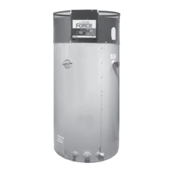
ULTRA FORCE
COMMERCIAL GAS WATER HEATER
• INSTALLATION • OPERATION • SERVICE • MAINTENANCE • LIMITED WARRANTY
WARNING: If the information in these
instructions is not followed exactly, a fire
or explosion may result causing property
damage, personal injury or death.
– Do not store or use gasoline or other
flammable vapors and liquids in the
vicinity of this or any other appliance.
– WHAT TO DO IF YOU SMELL GAS:
• Do not try to light any appliance.
• Do not touch any electrical switch;
do not use any phone in your
building.
• Immediately call your gas supplier
from a neighbor's phone. Follow the
gas supplier's instructions.
• If you cannot reach your gas supplier,
call the fire department.
– Installation and service must be
performed by a qualified installer,
service agency or the gas supplier.
Thank you for buying this energy efficient water heater from
State Industries. We appreciate your confidence in our
products.
TEXT PRINTED OR OUTLINED IN RED CONTAINS
INFORMATION RELATIVE TO YOUR SAFETY. PLEASE
READ THOROUGHLY BEFORE INSTALLING AND USING
THIS APPLIANCE.
PLACE THESE INSTRUCTIONS ADJACENT TO HEATER AND NOTIFY OWNER TO KEEP FOR FUTURE REFERENCE.
PRINTED IN U.S.A. 0706
®
SUF-130-300 AND SUF-130- 400
GAS-FIRED POWER BURNER
FOR DOMESTIC HOT WATER
CAUTION
500 TENNESSEE WALTZ PARKWAY
ASHLAND CITY, TN 37015
1
PART NO. 197483-000
Advertisement
Table of Contents

Related Manuals for State Water Heaters ULTRA FORCE SUF-130-300


Summary of Contents for State Water Heaters ULTRA FORCE SUF-130-300
- Page 1 ® ULTRA FORCE SUF-130-300 AND SUF-130- 400 COMMERCIAL GAS WATER HEATER GAS-FIRED POWER BURNER FOR DOMESTIC HOT WATER • INSTALLATION • OPERATION • SERVICE • MAINTENANCE • LIMITED WARRANTY WARNING: If the information in these instructions is not followed exactly, a fire or explosion may result causing property damage, personal injury or death.
-
Page 2: Rough-In Dimensions
ROUGH-IN-DIMENSIONS GAS VALVE PIPING SUF 130-300 1 1/4" NPT SUF 130-400 1 1/4" NPT TABLE 1 RECOVERY CAPACITIES. U.S. Gallons/Hr and Litres/Hr at TEMPERATURE RISE INDICATED TYPE OF INPUT Approx. F° 20F° 30F° 40F° 50F° 60F° 70F° 80F° 90F° 100F° 110° 120F°... -
Page 3: Table Of Contents
TABLE OF CONTENTS PAGE PAGE ROUGH-IN DIMENSIONS ............... Closed System ................15 FOREWORD ..................Water (Potable) Heating & Space Heating ........15-16 FEATURES ..................Heater Wiring .................. 16-17 Water Temperature Control ............OPERATION ..................18 Water Temperature Setpoint Adjustment Procedure ....Sequence of Operation .............. - Page 4 “AT A GLANCE” QUICK INSTALLATION TIPS Horizontal Sidewall Venting Vertical Rooftop Venting...
-
Page 5: Water Temperature Setpoint Adjustment Procedure
The temperature may be adjusted from 80°F/27°C to 180°F/82°C. Valves for reducing point-of-use temperature by mixing cold and The thermostat was adjusted to 120°F/49°C before the heater was hot water are available (see Figure 2). Also available are shipped from the factory. It is recommended that lower water inexpensive devices that attach to faucets to limit hot water temperatures be used to avoid the risk of scalding. -
Page 6: Circulating Pump
THE HEATER SHALL BE LOCATED OR PROTECTED SO IT IS CIRCULATING PUMP NOT SUBJECT TO PHYSICAL DAMAGE BY A MOVING VEHICLE. A circulating pump is used when a system requires a circulating loop or there is a storage tank used in conjunction with the heater. DO NOT LOCATE THE HEATER WHERE NOISE FROM THE Refer to the piping diagrams at rear of manual for electrical hookup EXHAUST OR INTAKE WILL BE OBJECTIONABLE. -
Page 7: Clearances
SERIOUS DAMAGE TO THE HEATER AND RISK OF FIRE OR CLEARANCES EXPLOSION. IT CAN ALSO CREATE A RISK OF ASPHYXIATION. These heaters are approved for installation on combustible flooring in an alcove when the minimum clearances from any combustion UNCONFINED SPACE construction are followed as indicated in Figure 4. - Page 8 US DIRECT VENT CAUTION TO PREVENT EXHAUSTING PRODUCTS FROM CIRCULATING TO THE AIR INTAKE IN WINDY/COLD AREAS, THE MAXIMUM PRACTICAL DISTANCE BETWEEN THESE TWO TERMINALS IS RECOMMENDED. CANADIAN DIRECT VENT FIGURE 5.
- Page 9 US HORIZONTAL VENT CAUTION TO PREVENT EXHAUSTING PRODUCTS FROM CIRCULATING TO THE AIR INTAKE IN WINDY/COLD AREAS, THE MAXIMUM PRACTICAL DISTANCE BETWEEN THESE TWO TERMINALS IS RECOMMENDED. CANADIAN HORIZONTAL VENT FIGURE 6.
-
Page 10: Vent Pipe Termination
Heater must be protected from freezing downdrafts during 3"x 4" PVC REDUCER WITH INTAKE GUARD shutdown periods. WARNING NEVER OPERATE THE HEATER UNLESS IT IS VENTED TO THE OUTDOORS AND HAS ADEQUATE AIR SUPPLY TO AVOID RISKS OF IMPROPER OPERATION, FIRE, EXPLOSION OR ASPHYXIATION. -
Page 11: Installation Sequence
Slide the pipe through the wall and insert into coupling on the 2. The horizontal centerline of the intake vent terminal may not be other side of the wall, making sure that the vent terminal ends located lower than the horizontal centerline of the exhaust vent up pointed in the correct position. -
Page 12: Installation Of Vent System
2. Drill a pilot hole approximately 1/4" (6 mm) outside of the marked exhaust venting arrangement of 15-equivalent feet. This is the circle. This pilot hole is used as a starting point for a saws-all or minimum amount of pipe required for the exhaust venting sabre saw blade. -
Page 13: Vent Pipe Preparation
WELL-VENTILATED AREA. CONTROLS AND SWITCHES FIGURE 13. The SUF-130-300 and 400 are equipped with four pressure switches. These switches are essential to the safe and proper operation of ON/OFF SWITCH the unit. All switches are wired in series. The controller is set up to shut the unit down whenever there is a failure of any of the switches. -
Page 14: Hot Surface Igniter
HOT SURFACE IGNITER FIRE OR EXPLOSION. IF OVERPRESSURE HAS OCCURRED SUCH AS THROUGH IMPROPER TESTING OF GAS LINES OR EMERGENCY MALFUNCTION OF THE SUPPLY SYSTEM THE The Hot Surface Igniter is a device that ignites the main burner by GAS VALVE MUST BE CHECKED FOR SAFE OPERATION. MAKE high temperature (>1800°F or >982°C). -
Page 15: Purging
THE HEATER. FOR TEST PRESSURES OF 1/2 PSIG (3.45Kpa) OR (ANSI) and pressure (ASME) relief valve(s). This relief valve shall LESS, THE APPLIANCE NEED NOT BE DISCONNECTED, BUT MUST comply with the standard for relief valves and automatic gas shutoff BE ISOLATED FROM THE SUPPLY PRESSURE TEST BY CLOSING devices for hot water supply systems. -
Page 16: Heater Wiring
4. When the system requires water for space heating at A POOR ELECTRICAL SUPPLY ARE NOT COVERED UNDER temperatures higher than required for domestic water purposes, YOUR WARRANTY. a tempering valve must be installed. Please refer to installation diagrams on pages 23 through 28 in back of manual for The controller is wired to the heater as shown in figures 15 &... - Page 17 FIGURE 16.
-
Page 18: Operation
OPERATION SELF DIAGNOSTIC CONTROLLER This controller is designed for ignition lockout after three consecutive SEQUENCE OF OPERATION failed attempts to light. If lockout occurs, the display lights will match Figure 17. Along with this, a numeric message will appear in the Typical Control/Appliance Operating Sequence display. -
Page 19: Error Codes
ERROR CODES Possible Cause Remedy The following Error Codes are external to the controller. 01 Pressure Switch Fail On, should be Off 1. No Input Power 1. Apply Power 11 Pressure Switch Fail Off, should be On 02 Ignition Fail after 3 attempts 2. -
Page 20: Switch Open
Display Flashes “05” when button is pressed: Possible Cause Remedy 1. Temperature Probe wiring 1. Repair Wiring open 2. Defective probe 2. Replace probe Display Flashes “15” when button is pressed: Possible Cause Remedy CONTROL BAD, All LEDs Flashing 1. No water in tank and tank 1. -
Page 21: Prior To Start-Up Required Ability
DO NOT USE THIS HEATER IF ANY PART HAS BEEN UNDER PRIOR TO START UP - REQUIRED ABILITY WATER. IMMEDIATELY CALL A QUALIFIED SERVICE INSTALLATION OR SERVICE OF THIS WATER HEATER TECHNICIAN TO INSPECT THE HEATER AND TO REPLACE ANY REQUIRES ABILITY EQUIVALENT TO THAT OF A LICENSED PART OF THE CONTROL SYSTEM AND ANY GAS CONTROL TRADESMAN IN THE FIELD INVOLVED. -
Page 22: Lighting Instructions
e. Repeat steps (c) and (d) until the specified input rate is c. Remove the pressure regulator cover screw (Figure 16) and achieved. adjust the pressure by turning the adjusting screw with a small screwdriver. In this example, with heater running on natural gas, do not exceed 4.0"... -
Page 23: Cathodic Protection
HYDROGEN GAS IS EXTREMELY FLAMMABLE. To reduce the risk of injury under these conditions, it is recommended that a hot FOR SUF-130-300 AND 400 water faucet be opened for several minutes before using any electrical NATURAL GAS appliance connected to the hot water system. If hydrogen is present, there will probably be an unusual sound such as air escaping through ELEVATION (ft./m) -
Page 24: Maintenance Schedule
direct proportion to water temperature and usage. The higher the MAINTENANCE SCHEDULE water temperature or water usage, the more lime deposits are dropped out of the water. This is the lime scale which forms in pipes, Following are the instructions for performing some of the heaters and on cooking utensils. -
Page 25: Powered Anode System
Replace with a new valve of the recommended size as necessary. Inspection of the valve should be performed at least The SUF-130-300/400 are factory equipped with a powered anode every three years. Do not attempt to repair the valve, as this could system. -
Page 26: Installation Diagrams
INSTALLATION DIAGRAMS ONE TEMPERATURE - ONE HEATER VERTICAL STORAGE TANK FORCED CIRCULATION WITH OR WITHOUT BUILDING RECIRCULATION CAUTION: IF BUILDING COLD WATER SUPPLY HAS A BACK- FLOW PREVENTER, CHECK VALVE OR WATER METER WITH CHECK VALVE PROVISIONS FOR THERMAL EXPANSION OF WATER IN THE HOT WATER SYSTEM MUST BE PROVIDED NOTE: CONNECT RETURN... - Page 27 TWO TEMPERATURE - ONE HEATER HIGH TEMPERATURE WITH OR WITHOUT BUILDING RECIRCULATION DANGER PIPE RELIEF VALVE TO OPEN DRAIN. TEMPERATURE SETTING SHOULD NOT EXCEED SAFE NOTE: TEMPERED WATER TEMPERATURE FIXTURES. WATER RECIRCULATED, RETURN LINE SHOULD BE TEMPERATURE CONTROL WARNING ON PAGE 3. IF CONNECTED AT POINT “A”.
- Page 28 TWO TEMPERATURE - TWO HEATERS HIGH TEMPERATURE WITH OR WITHOUT BUILDING RECIRCULATION TWO TEMPERATURE - THREE HEATERS (TWO PRE-HEATERS/ONE BOOSTER HEATER) WITH OR WITHOUT BUILDING RECIRCULATION MUST BE IDENTICAL HEATERS DANGER FOR MULTIPLE HEATER INSTALLATION SEE MANIFOLD KIT TEMPERATURE SETTING SHOULD NOT EXCEED SAFE SPECIFICATIONS, PAGE 30.
- Page 29 TWO TEMPERATURE - TWO HEATERS (ONE PRE-HEATER/ONE BOOSTER HEATER) WITH OR WITHOUT BUILDING RECIRCULATION DANGER * PIPE RELIEF VALVE TO OPEN DRAIN TEMPERATURE SETTING SHOULD NOT EXCEED SAFE TEMPERATURE AT FIXTURES. SEE WATER TEMPERATURE CONTROL WARNING ON ** 140°F (60°C)TO 150°F (66°C) SHOULD BE MAXIMUM WATER PAGE 3.
- Page 30 TWO TEMPERATURE - ONE HEATER HIGH TEMPERATURE WITH RECIRCULATION OF SANITIZING LOOP DANGER NOTE 1: TOGGLE SWITCH CONTROLS 180°F (82°C) WATER TEMPERATURE SETTING SHOULD NOT EXCEED SAFE CIRCULATION. INSTALL ON OR CLOSE TO DISHWASHER. TEMPERATURE AT FIXTURES. SEE WATER TEMPERATURE TOGGLE SWITCH MUST BE CLOSED (ON) DURING THE RINSE CONTROL WARNING ON PAGE 3.
-
Page 31: Manifold Kits
MANIFOLD KITS Precision cut type “L” all copper State manifold kits assure water flow balance of all units. Without this balance, the full water heating and storage potential of the system cannot be achieved. Plus, the units with the higher water flow may have a shortened life. Unions shown in piping diagrams are not included in the manifold kits. -
Page 32: Checklist And Service Information
CHECKLIST AND SERVICE INFORMATION 10. Condensate hose may be blocked where it connects to the exhaust elbow. IMPORTANT • Verify the condensate drains from the unit without restriction. The installer may be able to observe and correct certain problems which might arise when the unit is put into operation or when it is re- WATER IS TOO HOT fired after a prolonged shutdown. - Page 33 4. Check for open pressure switches or open reset button. Check Checking these four (4) items first will often result in a timely solution for blockage in the intake and exhaust venting or at the vent to the service call. hoods.
-
Page 34: Replacement Parts
Refer to the Yellow Pages for CAUTION where to call or contact the State Water Heaters, 500 Tennessee Do not reach into the burner housing or combustion chamber if the Waltz Parkway, Ashland City, TN 37015, 1-800-821-2017. When heater is still hot. -
Page 35: Limited Warranty
MODEL SUF-130-300NEA /PEA LIMITED WARRANTY State Water Heaters, the warrantor, extends the following LIMITED WARRANTY to the owner of this water heater. THE TANK If the glass-lined tank in this water heater shall prove upon examination by the warrantor to have leaked due to natural corrosion from potable water therein,... - Page 36 500 TENNESSEE WALTZ PARKWAY ASHLAND CITY, TN 37015 Phone: 800-365-0024 Fax: 800-644-9306 www.statewaterheaters.com...
Need help?
Do you have a question about the ULTRA FORCE SUF-130-300 and is the answer not in the manual?
Questions and answers