
Related Manuals for WLINK R520 series


Summary of Contents for WLINK R520 series
- Page 1 User M Manua ---Apply to R520 Series In n dustrial l 3G/4G R Router V3.0 http://www w.wlink-tech h.com 2014/12 2/25...
- Page 2 All sta atement, info rmation, sug ggestion.etc i n this file do es not comp pose form of guar rantee and w we WLINK re serves the ri ight of final e explanation. henzhen WLINK K Techno ology Co ompany...
- Page 3 Network k Setting .................... 2 2 3.5 VPN Tu unnel ........................ 2 8 3.6 System m Manageme ent ..................... 3 0 www.wlink‐te ech.com 2 ...
- Page 4 .......... 3 7 3.8 “RST” B Button for R Restore Facto ory Setting .............. 4 0 3.9 Append dix (For adva anced optio nal features s only) ............ 4 0 www.wlink‐te ech.com 3 ...
- Page 5 ,meanwh hile, WLINK K provide M 2M termina al managem ment platform m to manag e all rout ter terminal w with remote manageme ent.
- Page 6 Industri i al Cellular Ro nual outer User Ma le 1-1 Router r partial mode e l table Tabl www.wlink‐te ech.com 5 ...
- Page 7 ATM, POS .etc. www.wlink‐te ech.com 6 ...
- Page 8 Telne et/SSH + CL Option nal IPv6 prot tocol stack Option nal support M M2M termina al managem ment platform WDT w watchdog de esign, keep system stab Custom mization as customer’s demand www.wlink‐te ech.com 7 ...
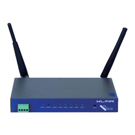
- Page 9 Panel WL-R520 St tructure Table 2-1 WLINK Te ech. 520 series Front Rear There are some different fo or Antenna interface a and indicat tor light for...
- Page 10 Not connecte Dark There are some d difference a among the L LED indicato or of expand ded Wi-Fi, G functio on and sing gle module/ /double SIM M, double module/dou uble SIM se eries produc cts. www.wlink‐te ech.com 9 ...
- Page 11 4.4 Powe er Supply y In o order to get high reliabi ility, WLINK K Series Rou uter adapt s supports wid de voltage i input rang ge: +5V~+3 36VDC, sup port hot plug...
- Page 12 Noti ice: Step 1 Check ant tenna connect tion. Step 2 Check SIM M/UIM card, co onfirm SIM/UI M card is ava ilable. Step Power on n the industria al Router ----E www.wlink‐te ech.com 11 ...
- Page 13 IP address s,192.168.1. .xxx(XXX ca an be any num mber betwee en 2~254) Step p 3 Run an Interneft Ex xplorer and v visit “ ” ”, to enter id dentify page. http://1 192.168.1.1/ www.wlink‐te ech.com 12 ...
- Page 14 WEB interfac ce, you can c check the cu urrent status s of Router, or modify ro outer conf figuration via a web interf face, below i is the introd uction for th he common s setting. www.wlink‐te ech.com 13 ...
- Page 15 Router Statu us GUI Figure 3-5 2.1 Cellu ular Net twork C Configur Step p 1 Single C Click Basic N Network-> C Cellular, you can modify relevant pa arameter accordin ng to the ap pplication. www.wlink‐te ech.com 14 ...
- Page 16 IP address. Step p 2 After Se etting, pleas e click “save e” icon. ----E 2.2 LAN N Setting Step p 1 Single C Click “ Basic c Network>L LAN” to ente r below inte rface www.wlink‐te ech.com 15 ...
- Page 17 Address Ra ange IP ad ddress rang e within LAN valid time Step p 2 After se etting, please e click “save e” to finish, t he device w will reboot. ----E www.wlink‐te ech.com 16 ...
- Page 18 Instruct Default is standard DDNS proto ocol, for cus stomized pro otocol, pleas address contact Wlink engin neer. Usually y, use defau ult IP 0.0.0.0 uto refresh Set the interval of th he DDNS cl ient obtains new IP, sug...
- Page 19 W WLAN para ameter throu ugh Web GU UI, below is the common n setting 3.1 Basi ic Settin Step p 1 Click “W WLAN->Basi ic Setting” to o configure r relative para ameter www.wlink‐te ech.com 18 ...
- Page 20 HZ and 40M MHZ alternat tive ecurity Supp port various encryption method Step p 2 Please click “Save” ” to finish. ----E 3.2 Wire eless Fi lter Set ting Step p 1 Single c click “WLAN > Wireless Filter”. www.wlink‐te ech.com 19 ...
- Page 21 Step p 2 Please click ”save” to finish ----E 3.3 Adva anced W Wireless s Settin Step p 1 Please click “WLAN N> Advanced d Wireless” to check or modify the relevant parame eter. www.wlink‐te ech.com 20 ...
- Page 22 3-7 Advan ced Wireless s Setting GUI Figu Step p 2 Please click ”save” to finish. ----E 3.4 Wire eless Su urvey Step p 1 Please click “WLAN N> Wireless Survey” to c check surve www.wlink‐te ech.com 21 ...
- Page 23 1 Please click “Adva nced Netwo ork > Port F Forwarding” to enter the e GUI, you modify the router name, Ho ost name a and Domain n name ac ccording to applicat tion requirem ment. www.wlink‐te ech.com 22 ...
- Page 24 3-10 DMZ G Figure “DMZ” Instru uction Table 3-8 rameter Instruct estination The des stination add dress inside the LAN. ddress ource If no IP address ins ide, it will all low all IP ad ddress to acc cess. www.wlink‐te ech.com 23 ...
- Page 25 Port trig ggering open ns an incom ing port whe en your comput er is using a a specified o outgoing por rt for specific traffic. Step p 2 Please click ”save” to finish. ----E www.wlink‐te ech.com 24 ...
- Page 26 Black lis esources Step p 2 Please click ”save” to finish. 4.5 Seria al App. Setting Step p 1 Please click “Advan nced Networ rk> Serial A pp” to check k or modify t the relevant parame eter. www.wlink‐te ech.com 25 ...
- Page 27 Heart be eat interval time erval aud Rate 115200 as default arity Bit None as s default ata Bit 8bit as d default op Bit 1bit as d default Step p 2 Please click ”save” to finish. www.wlink‐te ech.com 26 ...
- Page 28 Step p 2 Please click ”save” to finish. 4.7 Stat ic DHCP P Settin Step p 1 Please click “Advan nced Networ rk> Static D HCP” to che eck or modif fy the releva parame eter. www.wlink‐te ech.com 27 ...
- Page 29 Usually a a public IP ad ddress ddress cal IP Local IP P address fo or LAN. ddress nnel Local I GRE Tu unnel local I P address w which is a vir rtual IP addr ress. dress www.wlink‐te ech.com 28 ...
- Page 30 As the c configuration n requested ateless As the c configuration n requested ccept DNS As the c configuration n requested emote Subne As the c configuration n requested eate NAT on As the c configuration n requested www.wlink‐te ech.com 29 ...
- Page 31 3 32 character r, it is the dom main of WAN N, no need to o configure f for most applicat tion. Step p 2 Please click ”save” to finish ----E www.wlink‐te ech.com 30 ...
- Page 32 3-18 Sys stem Configu uration GUI If the e device is o online but tim me update is s fail, please try other NT TP Time Se rver. Step p 2 Please click “save t to finish. ----E www.wlink‐te ech.com 31 ...
- Page 33 Please n note the “pa assword” is t he router sy ystem accou unt password Admin Settin ng GUI Figure 3-19 Step p 2 Please click save ir ron to finish the setting ----E www.wlink‐te ech.com 32 ...
- Page 34 Figu Step p 2 Please click save ir ron to finish the setting ----E 6.5 SNM MP Setti Step p 1 Please click “Admin nistrator>SN NMP” to chec ck and mod ify relevant parameter. www.wlink‐te ech.com 33 ...
- Page 35 2 Please click save ir ron to finish the setting ----E End 6.7 Back kup Set tting Step p 1 Please click “ Admi nistrator> B ack up Conf figuration ” t to do the ba ckup setting www.wlink‐te ech.com 34 ...
- Page 36 Default w would lose al l configurati on informati ion, please b be careful. Step p 2 After se etting the bac ckup and re estore config guration. The e system wil ll reboot automa tically. ----E www.wlink‐te ech.com 35 ...
- Page 37 (Local or remote se ever). Figure 3-24 Sy ystem log Se etting GUI Step p 2 After co onfigure, plea ase click “Sa ave” to finish ----E www.wlink‐te ech.com 36 ...
- Page 38 ----E Debu ugging Setting 7.1 Logs s Settin Step p 1 Please click “Debug gging>Logs” ” to check a nd modify re elevant para ameter. www.wlink‐te ech.com 37 ...
- Page 39 Figure Step p 2 After co onfigure, plea ase click “Sa ave” to finish ----E End 7.3 Trac ce Settin Step p 1 Please click “Debug gging>Trace e” to check a and modify r relevant par rameter. www.wlink‐te ech.com 38 ...
- Page 40 Industri nual ial Cellular Ro outer User Ma 3-28 Trace G Figure 3 Step p 2 After co onfigure, plea a se click “Sa ave” to finish ----E End www.wlink‐te ech.com 39 ...
- Page 41 9.1 Cellu ular Set tting (D ual-SIM Step p 1 Single C Click Basic N Network-> C Cellular, you can modify relevant pa arameter accordin ng to the ap pplication. www.wlink‐te ech.com 40 ...
- Page 42 3 se conds. If the e third time i is still failed, , the router wil l switch the SIM card. The Chec ck IP is a pu ublic IP or co ompany serv ver IP addre ess. www.wlink‐te ech.com 41 ...
- Page 43 SIM2 withi n the define ed time. Onc ce the time is s over, it will l switch bac k to SIM1. Step p 2 After Se etting, pleas e click “save e” icon. ----E www.wlink‐te ech.com 42 ...
- Page 44 Payloa The ma ax packet for r GPS data. eart-Beat GPS he eart beat pac cket. ontent eart-Beat The hea art beat pac ket interval. erval Step p 2 Please click ”save” to finish www.wlink‐te ech.com 43 ...
- Page 45 GPS data f format as be elow. dtu. heartbeat.co ontent,gps_ _date, gps_ti me, gps_us se, gps_latitu ude, gps_NS S, gps_longi itude, gps_ _EW, gps_s speed, gps_ _degrees, gp ps_FS, gps_ _HDOP, gps_ _MSL e.g. uter_00001,0 083238,120 313,12,2230 0.31563,N,1 11355.02863 www.wlink‐te ech.com 44 ...
Need help?
Do you have a question about the R520 series and is the answer not in the manual?
Questions and answers