Sony Ericsson W580 Working Instruction, Mechanical
Hide thumbs
Also See for W580:
- User manual (82 pages) ,
- Specifications (2 pages) ,
- Working instruction, mechanical (58 pages)
Table of Contents
Advertisement
Quick Links
Download this manual
See also:
User Manual
Working Instruction, Mechanical
Applicable for S500, W580
CONTENTS
1 Introduction .............................................................................. 3
1.1 View of S500 and W580............................................................3
1.2 Tools and Equipment...............................................................4
1.3 General Cautions......................................................................5
1.4 Adhesives .................................................................................5
1.5 Using Hand and ESD Protection.............................................5
1.6 Protection of Displays, Lenses, and Windows......................5
1.7 Acceptable Pry Tools...............................................................5
2 Disassembly ............................................................................. 6
2.1 Overview ...................................................................................6
3 Part Replacement................................................................... 24
3.1 Bluetooth Antenna .................................................................24
3.2 Bonzer Flex .............................................................................26
3.3 Camera ....................................................................................29
3.4 Camera Cover .........................................................................30
3.5 Chin Cover ..............................................................................30
3.6 Coaxial Cable and Antenna ...................................................31
3.7 Front Cover .............................................................................31
3.8 Front Frame ............................................................................32
3.9 Hinge Assembly .....................................................................32
3.10 Keypad ....................................................................................33
3.11 LCD Assembly ........................................................................34
3/000 21-1/FEA 209 544/603 C
©
Company Internal
Sony Ericsson Mobile
Communications AB
2.1.1
Battery Cover Removal ......................................................... 7
2.1.2
Battery Removal.................................................................... 7
2.1.3
Label Removal ...................................................................... 8
2.1.4
Front Cover Removal ............................................................ 9
2.1.5
Camera Cover Removal...................................................... 11
2.1.6
Front Cover Screw Removal (6 screws).............................. 12
2.1.7
Front Frame Removal ......................................................... 13
2.1.8
Upper Rear Cover Removal ................................................ 18
2.1.9
Rear Frame Screw Removal (4 screws).............................. 19
2.1.10 Chin Cover Removal ........................................................... 20
2.1.11 Hinge Assembly Removal from Rear Frame ....................... 21
2.1.13 Antenna/Cable Assembly Removal from PC Board ............ 23
Working Instruction, Mechanical
Advertisement
Table of Contents

Related Manuals for Sony Ericsson W580


Summary of Contents for Sony Ericsson W580
-
Page 1: Table Of Contents
Working Instruction, Mechanical Working Instruction, Mechanical Applicable for S500, W580 CONTENTS 1 Introduction ................3 1.1 View of S500 and W580............3 1.2 Tools and Equipment...............4 1.3 General Cautions..............5 1.4 Adhesives .................5 1.5 Using Hand and ESD Protection..........5 1.6 Protection of Displays, Lenses, and Windows......5 1.7 Acceptable Pry Tools...............5... - Page 2 Camera Cover Installation........... 67 4.1.10 Front Cover Installation ............68 4.1.11 Label Installation ..............69 4.1.12 Battery Installation............... 70 4.1.13 Battery Cover Installation ............ 70 5 Revision History..............71 3/000 21-1/FEA 209 544/603 C 2(71) © Sony Ericsson Mobile Communications AB...
-
Page 3: Introduction
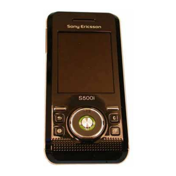
Working Instruction, Mechanical 1 Introduction View of S500 and W580 S500 W580 3/000 21-1/FEA 209 544/603 C © Company Internal Sony Ericsson Mobile Communications AB... -
Page 4: Tools And Equipment
• ESD-wristband • ESD-gloves LABEL EQUIPMENT The following special equipment is required when replacing or installing a new label: • Hot air device • Zebra printer connected to computer 3/000 21-1/FEA 209 544/603 C 4(71) © Sony Ericsson Mobile Communications AB... -
Page 5: General Cautions
1.7 Acceptable Pry Tools Whenever the phrase “pry tool” is used, a nylon pointer or a front opening tool may be used depending on the user’s preference. 3/000 21-1/FEA 209 544/603 C 5(71) © Sony Ericsson Mobile Communications AB... -
Page 6: Disassembly
Remove Hinge Assembly (11) from Rear Frame (12) • Remove PC Board/Antenna Assembly (13 &14) from Rear Frame (12) • Remove Antenna/cable Assembly (14) from PC Board (13) 3/000 21-1/FEA 209 544/603 C © Company Internal Sony Ericsson Mobile Communications AB... -
Page 7: Battery Cover Removal
Use thumbs to push the battery cover down until it stops. Lift the end of the battery cover to remove it. 2.1.2 Battery Removal Use a finger to lift the battery up. 3/000 21-1/FEA 209 544/603 C 7(71) © Sony Ericsson Mobile Communications AB... -
Page 8: Label Removal
Use rounded tip tweezers to start the peeling up of the label. Once the peeling of the label is started, use your fingers to remove the label. NOTE: BE CAREFUL WHEN PULLING THE LABEL OFF THE FLEX CONNECTOR. 3/000 21-1/FEA 209 544/603 C 8(71) © Sony Ericsson Mobile Communications AB... -
Page 9: Front Cover Removal
Continue around the top left corner to release the upper left corner latch. STOP Once the top of the volume key is reached remove the HERE plectrum from the seam. 3/000 21-1/FEA 209 544/603 C 9(71) © Sony Ericsson Mobile Communications AB... - Page 10 Then slide the cover down towards the keypad and off of the frame. NOTE: DO NOT ROTATE THE FRONT COVER TOO FAR OR THE BOTTOM PEGS WILL BE DAMAGED. Separate the navigation keypad from the front cover. 3/000 21-1/FEA 209 544/603 C 10(71) © Sony Ericsson Mobile Communications AB...
-
Page 11: Camera Cover Removal
Insert a plectrum between the camera cover and the frame in the location shown to pry the cover up. Pull the lifted end of the camera cover as shown to remove the camera cover. 3/000 21-1/FEA 209 544/603 C 11(71) © Sony Ericsson Mobile Communications AB... -
Page 12: Front Cover Screw Removal (6 Screws)
Slide the hinge partially closed until the remaining 2 screws are visible. While holding the hinge in the partially closed position, remove the screws. NOTE: DO NOT REUSE THE SCREWS. 3/000 21-1/FEA 209 544/603 C 12(71) © Sony Ericsson Mobile Communications AB... -
Page 13: Front Frame Removal
NOTE: THE TWO HALVES OF THE PHONE WILL HAVE TO BE HELD IN PLACE TO MAINTAIN THIS ALIGNMENT. Lift the bottom edge of the phone’s upper half approximately 10-15 mm. 3/000 21-1/FEA 209 544/603 C 13(71) © Sony Ericsson Mobile Communications AB... - Page 14 NOTE: THE LCD ASSEMBLY MUST BE DETTACHED BEFORE DISCONNECTING THE FLEX CONNECTION BETWEEN THE FRONT HALF OF THE PHONE AND THE HINGE ASSEMBLY TO REDUCE THE RISK OF FLEX FILM DAMAGE. 3/000 21-1/FEA 209 544/603 C 14(71) © Sony Ericsson Mobile Communications AB...
- Page 15 Insert the tip of the plectrum between the left side of the LCD assembly and the front frame. Rotate the plectrum away for the LCD to release the lower left side retention feature. 3/000 21-1/FEA 209 544/603 C 15(71) © Sony Ericsson Mobile Communications AB...
- Page 16 Rotate the plectrum away for the LCD to release the lower right side retention feature. Free the upper two LCD retention features by wiggling to LCD to the left and right. 3/000 21-1/FEA 209 544/603 C 16(71) © Sony Ericsson Mobile Communications AB...
- Page 17 THIS CONNECTION TOGETHER. BE CAREFUL NOT THE DAMAGE THE BONZER FLEX OF THE HINGE FLEX WHEN TRYING THE SEPARATE THE CONNECTION. Once the hinge flex is disconnected, remove the front frame. 3/000 21-1/FEA 209 544/603 C 17(71) © Sony Ericsson Mobile Communications AB...
-
Page 18: Upper Rear Cover Removal
Lift up on the rear cover to release the middle and right side latches. Pull the rear cover down and rotate the lifted end of the cover away from the rear frame. 3/000 21-1/FEA 209 544/603 C 18(71) © Sony Ericsson Mobile Communications AB... -
Page 19: Rear Frame Screw Removal (4 Screws)
Working Instruction, Mechanical 2.1.9 Rear Frame Screw Removal (4 screws) Use a torque wrench and a JCIS-0 bit to remove the 4 screws. NOTE: DO NOT REUSE THE SCREWS. 3/000 21-1/FEA 209 544/603 C 19(71) © Sony Ericsson Mobile Communications AB... -
Page 20: Chin Cover Removal
Using the plectrum, lift up of the left end of the chin cover to get the chin cover to unsnap from the rear frame. Remove the microphone gasket using your fingers. 3/000 21-1/FEA 209 544/603 C 20(71) © Sony Ericsson Mobile Communications AB... -
Page 21: Hinge Assembly Removal From Rear Frame
Lift the “non-keypad” end of the hinge assembly away from the rear frame. Use a pry tool to unplug the hinge-to-board connector. 3/000 21-1/FEA 209 544/603 C 21(71) © Sony Ericsson Mobile Communications AB... -
Page 22: Pc Board/Antenna Assembly Removal From Rear Frame
Grip the middle of the antenna assembly and rotate it away from the circuit board to free the antenna from the rear frame Leave the antenna sitting on the rear frame over its cavity. 3/000 21-1/FEA 209 544/603 C 22(71) © Sony Ericsson Mobile Communications AB... -
Page 23: Antenna/Cable Assembly Removal From Pc Board
CONNECTOR MAY BE DAMAGED. Insert the slot of the tool onto the end of the coaxial cable connector. Pull the connector directly away from the PC board. NOTE: DO NOT ROTATE. 3/000 21-1/FEA 209 544/603 C 23(71) © Sony Ericsson Mobile Communications AB... -
Page 24: Part Replacement
Remove the Bluetooth antenna from the rear frame by sliding it toward the edge of the frame. Installation Insert the bent pins of the antenna into the slots of the frame. 3/000 21-1/FEA 209 544/603 C 24(71) © Sony Ericsson Mobile Communications AB... - Page 25 Reinstall the upper rear cover, battery, and battery cover as Align instructed in reassembly procedure 4.1.5, 4.1.12, and 4.1.13. Edge 3/000 21-1/FEA 209 544/603 C 25(71) © Sony Ericsson Mobile Communications AB...
-
Page 26: Bonzer Flex
Pull the volume key switches out of the slot of the front frame. Push the camera out of its cavity. Fold the camera portion of the flex in front of the LCD connector. 3/000 21-1/FEA 209 544/603 C 26(71) © Sony Ericsson Mobile Communications AB... - Page 27 Push the bottom of the speaker box from the frame. Installation Fold the top corners of the dome foil a small amount off the speaker box. 3/000 21-1/FEA 209 544/603 C 27(71) © Sony Ericsson Mobile Communications AB...
- Page 28 Fold the top corners of the navigation keypad down onto the frame. Insert the camera into its cavity. Insert the volume switches into their cavity. 3/000 21-1/FEA 209 544/603 C 28(71) © Sony Ericsson Mobile Communications AB...
-
Page 29: Camera
Insert the pegs into the slots and press the tool completely onto the camera. Remove the tool and the camera from the socket. 3/000 21-1/FEA 209 544/603 C 29(71) © Sony Ericsson Mobile Communications AB... -
Page 30: Camera Cover
Perform sections 4.1.9 - 4.1.10 of the reassembly procedure. 3.5 Chin Cover Removal Perform section 2.1.10 of the disassembly procedure. Obtain a new Chin Cover. Installation Perform section 4.1.6 of the reassembly procedure. 3/000 21-1/FEA 209 544/603 C 30(71) © Sony Ericsson Mobile Communications AB... -
Page 31: Coaxial Cable And Antenna
Perform sections 4.1.1 – 4.1.13 of the reassembly procedure 3.7 Front Cover Removal Perform section 2.1.4 of the disassembly procedure. Obtain a new Front Cover. Installation Perform section 4.1.10 of the reassembly procedure. 3/000 21-1/FEA 209 544/603 C 31(71) © Sony Ericsson Mobile Communications AB... -
Page 32: Front Frame
Perform sections 2.1.1 -2.1.11 of the disassembly procedure Obtain a new Hinge Assembly Installation Perform the installation portion of the Wear Strip Replacement procedure Perform sections 4.1.3 -4.1.13 of the reassembly procedure 3/000 21-1/FEA 209 544/603 C 32(71) © Sony Ericsson Mobile Communications AB... -
Page 33: Keypad
Apply pressure over the surface of the keypad so that a good bond to the hinge assembly occurs. Reinstall the microphone gasket and chin cover as instructed in section 4.1.6 of the reassembly procedure. 3/000 21-1/FEA 209 544/603 C 33(71) © Sony Ericsson Mobile Communications AB... -
Page 34: Lcd Assembly
Insert the tip of the plectrum between the left side of the LCD assembly and the front frame. Rotate the plectrum away for the LCD to release the lower left side retention feature. 3/000 21-1/FEA 209 544/603 C 34(71) © Sony Ericsson Mobile Communications AB... - Page 35 Rotate the plectrum away for the LCD to release the lower right side retention feature. Free the upper two LCD retention features by wiggling to LCD to the left and right. 3/000 21-1/FEA 209 544/603 C 35(71) © Sony Ericsson Mobile Communications AB...
- Page 36 Installation Orient the LCD as shown and plug the LCD’s flex into the bonzer flex. Fold the LCD so that it lays over its cavity. 3/000 21-1/FEA 209 544/603 C 36(71) © Sony Ericsson Mobile Communications AB...
- Page 37 Insert the tip of the plectrum between the left side of the LCD assembly and the front frame. Rotate the plectrum towards the LCD to insert the lower left side retention feature into its slot in the front frame. 3/000 21-1/FEA 209 544/603 C 37(71) © Sony Ericsson Mobile Communications AB...
- Page 38 Rotate the plectrum towards the LCD to insert the lower right side retention feature into its slot in the front frame. Reinstall the front cover as instructed in section 4.1.10 of the reassembly procedure. 3/000 21-1/FEA 209 544/603 C 38(71) © Sony Ericsson Mobile Communications AB...
-
Page 39: Liquid Intrusion Indicator
Remove the old liquid intrusion indicator Installation Align the bottom, left corner of the new indicator with the edge of the slot in the hinge. Perform sections 4.1.3 -4.1.13 of the reassembly procedure 3/000 21-1/FEA 209 544/603 C 39(71) © Sony Ericsson Mobile Communications AB... -
Page 40: Main Keypad Flex
Use a pry tool to disconnect the flex connection. Use a pry tool to remove the vibrator. Lift the microphone flex off the hinge. Pull the vibrator pads through the slot in the hinge. 3/000 21-1/FEA 209 544/603 C 40(71) © Sony Ericsson Mobile Communications AB... - Page 41 Apply pressure over the dome foil portion of the keypad flex so that a good bond is formed 3/000 21-1/FEA 209 544/603 C 41(71) © Sony Ericsson Mobile Communications AB...
- Page 42 Push the vibrator down into place. Plug the keypad flex to the hinge flex. Perform sections 4.1.3 -4.1.13 of the reassembly procedure Perform the installation portion of the Keypad Replacement procedure 3/000 21-1/FEA 209 544/603 C 42(71) © Sony Ericsson Mobile Communications AB...
-
Page 43: Memory Stick Cover
Pull the memory stick cover out of its cavity. Rotate the memory stick cover down to free the inside latch from the peg on the frame. Pull the cover out of the hole. 3/000 21-1/FEA 209 544/603 C 43(71) © Sony Ericsson Mobile Communications AB... - Page 44 Make sure the tab is behind the peg. Push the cover into its cavity. Replace the Camera Cover and Front Cover as in 4.1.9- 4.1.10 of the reassembly procedure. 3/000 21-1/FEA 209 544/603 C 44(71) © Sony Ericsson Mobile Communications AB...
-
Page 45: Microphone
Orient the microphone so the pins are toward the phone and the side of the microphone that its contact pins are closest too is toward the keypad dome foil. Insert the pins into the holes. 3/000 21-1/FEA 209 544/603 C 45(71) © Sony Ericsson Mobile Communications AB... -
Page 46: Microphone Gasket
Remove the battery cover, battery, and front cover as instructed in disassembly procedure 2.1.1, 2.1.2, and 2.1.4. Installation Reinstall the front cover, battery, and battery cover as instructed in reassembly procedure 4.1.10, 4.1.12, and 4.1.13 3/000 21-1/FEA 209 544/603 C 46(71) © Sony Ericsson Mobile Communications AB... -
Page 47: Power Key
Press the coaxial cable ground pad into the cable slot. Perform the reassembly procedure starting at section 4.1.2 3/000 21-1/FEA 209 544/603 C 47(71) © Sony Ericsson Mobile Communications AB... -
Page 48: Receiver And Gasket
Perform the installation portion of the Bonzer Flex Replacement procedure Perform the installation portion of the Volume Key Replacement procedure Perform the reassembly procedure starting at section 4.1.7 3/000 21-1/FEA 209 544/603 C 48(71) © Sony Ericsson Mobile Communications AB... -
Page 49: System Connector
Perform sections 2.1.1-2.1.12 of the disassembly procedure Pull the system connector off of the PC board. Installation Push the system connector onto the PC board. Perform the reassembly procedure starting at section 4.1.2 3/000 21-1/FEA 209 544/603 C 49(71) © Sony Ericsson Mobile Communications AB... -
Page 50: Upper Rear Cover
Orient the vibrator so that its spring fingers are toward the vibrator contact pads and insert the vibrator into its cavity. Push the vibrator down into place. Perform the reassembly procedure starting at section 4.1.3 3/000 21-1/FEA 209 544/603 C 50(71) © Sony Ericsson Mobile Communications AB... -
Page 51: Volume Key
Work the volume key into its opening so that the features at each end of the volume key mate with the features of the frame as shown. Reinstall the front cover as instructed in reassembly procedure 4.1.10 3/000 21-1/FEA 209 544/603 C 51(71) © Sony Ericsson Mobile Communications AB... -
Page 52: Wear Strips
Align the tabs on the hinge assembly with the holes in the wear strip. Snap the wear strip onto the hinge assembly. Perform the reassembly procedure starting at section 4.1.3 3/000 21-1/FEA 209 544/603 C 52(71) © Sony Ericsson Mobile Communications AB... -
Page 53: Reassembly
Install 6 Front Cover Screws (not shown) • Install Camera Cover (13) • Install Front Cover (12) • Install Label (11) • Install Battery (10) • Install Battery Cover (9) 3/000 21-1/FEA 209 544/603 C 53(71) © Sony Ericsson Mobile Communications AB... -
Page 54: Antenna/Cable Assembly Installation To Pc Board
Using the tool, snap the connector onto the PC board. Rotate the coax cable so that it is oriented to the circuit board as shown. 3/000 21-1/FEA 209 544/603 C 54(71) © Sony Ericsson Mobile Communications AB... -
Page 55: Pc Board And Antenna Installation
NOTE: THE TWO SNAPS SHOULD REST AGAINST ITS SIM CONNECTOR SIDE OF THE CIRCUIT BOARD. 3/000 21-1/FEA 209 544/603 C 55(71) © Sony Ericsson Mobile Communications AB... - Page 56 Install the Bluetooth tape using tweezers. Align the tape with the inside edge of the system connector and leave two holes exposed. Align Edge 3/000 21-1/FEA 209 544/603 C 56(71) © Sony Ericsson Mobile Communications AB...
-
Page 57: Hinge Assembly Installation To Rear Frame
NOTE: MAKE SURE THE MICROPHONE FLEX IS UNDER THE TABS OF THE ANTENNA PLASTIC. Snap the tab on one side of the frame in the slot on the hinge. 3/000 21-1/FEA 209 544/603 C 57(71) © Sony Ericsson Mobile Communications AB... -
Page 58: Rear Frame Screw Installation (4 Screws)
4.1.4 Rear Frame Screw Installation (4 Screws) NOTE: DO NOT REUSE THESE SCREWS. Use 8 N*cm and a JCIS No. 0 bit to install the four new screws. 3/000 21-1/FEA 209 544/603 C 58(71) © Sony Ericsson Mobile Communications AB... -
Page 59: Upper Rear Cover Installation
4.1.5 Upper Rear Cover Installation Insert the two indicated tabs on the upper rear cover into the slots on the frame. Rotate the cover down toward the phone. 3/000 21-1/FEA 209 544/603 C 59(71) © Sony Ericsson Mobile Communications AB... - Page 60 Working Instruction, Mechanical Snap the remaining 3 tabs into place. (Shown in pictures 1, 2, and 3) 3/000 21-1/FEA 209 544/603 C 60(71) © Sony Ericsson Mobile Communications AB...
-
Page 61: Chin Cover Installation
Press the gasket over the microphone as shown. Insert the tabs of the chin cover into the slots. Push down on the cover to snap all the tabs into place. 3/000 21-1/FEA 209 544/603 C 61(71) © Sony Ericsson Mobile Communications AB... -
Page 62: Front Frame Installation
NOTE: ALIGN THE EDGE OF THE TAPE WITH THE EDGE OF THE FLEX AS INDICATED. Remove the protective film from each piece of tape. 3/000 21-1/FEA 209 544/603 C 62(71) © Sony Ericsson Mobile Communications AB... - Page 63 Apply a small amount of pressure so that the tape bonds. Orient the LCD as shown and plug the LCD’s flex into the bonzer flex. Fold the LCD so that it lays over its cavity. 3/000 21-1/FEA 209 544/603 C 63(71) © Sony Ericsson Mobile Communications AB...
- Page 64 Insert the tip of the plectrum between the left side of the LCD assembly and the front frame. Rotate the plectrum towards the LCD to insert the lower left side retention feature into its slot in the front frame. 3/000 21-1/FEA 209 544/603 C 64(71) © Sony Ericsson Mobile Communications AB...
- Page 65 Holding the front frame and hinge assembly at the top, slide the phone closed. Press in on the front frame at two side latches to get the hinge and front frame latched together. 3/000 21-1/FEA 209 544/603 C 65(71) © Sony Ericsson Mobile Communications AB...
-
Page 66: Front Frame Screw Installation (6 Screws)
Use 6 N*cm and a JCIS No. 0 bit to install the new screws. Push the hinge open and install the remaining four screws. 3/000 21-1/FEA 209 544/603 C 66(71) © Sony Ericsson Mobile Communications AB... -
Page 67: Camera Cover Installation
Insert the bottom edge of a new cover into the slot indicated. Slot Push the cover down into the front frame so the surfaces of the cover are flush with the edges of the front frame. 3/000 21-1/FEA 209 544/603 C 67(71) © Sony Ericsson Mobile Communications AB... -
Page 68: Front Cover Installation
4.1.10 Front Cover Installation Place the keypad into the front cover. Slide the hooks at the bottom of the front cover into the slots on the frame. 3/000 21-1/FEA 209 544/603 C 68(71) © Sony Ericsson Mobile Communications AB... -
Page 69: Label Installation
Insert the top side of the label under the battery connector. Push the label down into the battery cavity and make sure the Liquid Intrusion Indicator shows through the square hole. 3/000 21-1/FEA 209 544/603 C 69(71) © Sony Ericsson Mobile Communications AB... -
Page 70: Battery Installation
Insert the tabs of the battery cover into the slots on the frame. Push the bottom edge of the battery cover downward and towards the top of the phone to get the battery cover to slide into place. 3/000 21-1/FEA 209 544/603 C 70(71) © Sony Ericsson Mobile Communications AB... -
Page 71: Revision History
Updated disassembly and reassembly procedures to accommodate the addition of the tape between the bonzer and hinge flexs • Updated blurry pics • 2007-September-5 Updated references in replacement sections 3/000 21-1/FEA 209 544/603 C 71(71) © Sony Ericsson Mobile Communications AB...
Need help?
Do you have a question about the W580 and is the answer not in the manual?
Questions and answers