Table of Contents
Advertisement
Advertisement
Table of Contents

Related Manuals for SGM Giotto spot 400


Summary of Contents for SGM Giotto spot 400
-
Page 2: General Instructions
S SERIAL NUMBER AND MODEL WHEN CONTACTING YOUR RESELLER FOR INFORMATION OR ASSISTANCE Protect the environment: don't throw packing material into your garbage can return it to your SGM retailer or take it to the nearest special waste collection point. -
Page 3: Table Of Contents
index ............1 ENERAL ARNINGS AND NSTRUCTIONS... -
Page 4: Resentation
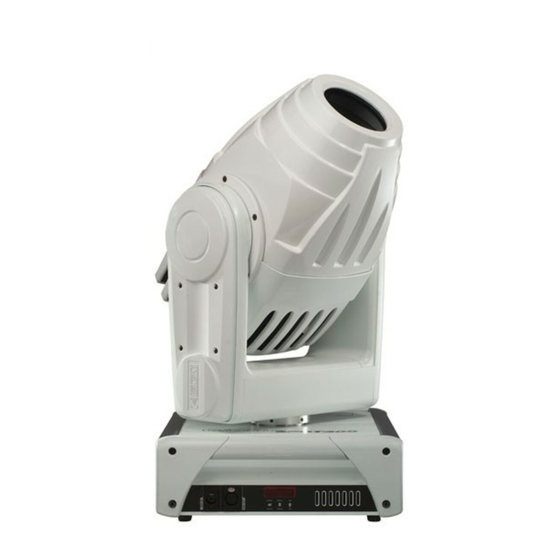
Giotto Spot is SGM's innovative professional moving head spot, specifically manufactured for use in high profile shows, theatres, Television studios and entertainment venues in general. Thanks to its cutting edge performance, the result of SGM's lengthy experience in mechanical and electronic design, Giotto Spot is one of the world's best. -
Page 5: Main Features
Main features Lamp Giotto Spots use a Philips MSD 400HR (6000°K) discharge lamp. Effects - Linear zoom (9° - 24°) - Fast linear iris - Automatic electronic focus - Linear dimmer ( 0-100% ) - Shutter / strobe 12 fps with music sync - Colour wheel with 8 positions + white, supplied as standard with 8 dichroic colours - Effects wheel with 8 positions + white, fitted with 2 conv. -
Page 6: Accessories
Accessories - Single flight case cod:0061745 - Double flight case cod:0061746 Symbols used THIS SYMBOL INDICATES A GENERAL RISK THIS SYMBOL INDICATES ELECTRIC SHOCK RISK THIS SYMBOL INDICATES A HOT SURFACE THIS SYMBOL MEANS “DO NOT PLACE THE UNIT ON INFLAMMABLE PARTS OR MATERIAL” THIS SYMBOL INDICATES THAT THE MINIMUM DISTANCE BETWEEN THE FIXTURE AND THE SURFACE TO BE LIT MUST BE NO LESS THAN 1.5 METRES GiottoSpot 400 rel.1.01... -
Page 7: Lectrical Pecifications
ERMOPLAST WEIGHT: 24.8 KG. DIMENSIONS (MM.) SGM Elettronica reserves the right to improve or modify its products at any time. Always refer to the manual supplied with the unit to avoid any risk of mistakes or operation which does not correspond to manual indications. -
Page 8: Nstallation
Changes to this manual SGM has an on-going product development policy, so the information printed in this manual may not be completely up to date. If any doubts arise regarding the topics covered in this manual or should any further help be required, our online services (internet-server www.sgm.it... -
Page 9: Ccess To Internal Components
Installation 1.2 Access to internal components Giotto fixtures have a simple head opening mechanism. All work must ALWAYS be carried out by qualified technical personnel. ATTENTION: make certain that the fixture is switched off and that there is no risk of burns due to high component temperature (wait at least 30 minutes after switching off) To access internal components, proceed as follows: 1. -
Page 10: Nstalling The Lamp
Installation 1.3 Installing the lamp ATTENTION! This fixture is designed exclusively for use with Philips MSD 400HR lamps. NEVER USE ANY OTHER TYPES OF LAMPS. • ISCONNECT THE POWER SUPPLY BEFORE CARRYING OUT ANY WORK ON THE FIXTURE • AKE CERTAIN THAT THE FIXTURE IS OFF AND THE TEMPERATURE OF THE COMPONENTS CAN T CAUSE BURNS WAIT AT LEAST... -
Page 11: Lamp Alignment
Installation 1.4 Lamp alignment Every time a new lamp is installed in the fixture, it must be aligned with the optical system to ensure optimum even light output from the unit. 1. Install the new lamp (par. 1.3), close the fixture and switch it on 2. -
Page 12: Ifitting Removal Gobo Adapter
Installation 1.6 Fitting/removal gobo adapter FITTING: Select the position in which the adapter is to be installed on the effects wheel, remove the colour filter if there is one (par. 1.7), open the disks (3) using the least possible force, slide the spring (A) in until it fits into the engraved slot, then fit the adapter (B) by pushing lightly in the direction indicated by the arrow. -
Page 13: Constructing A Power Cord
Installation 1.8 Power cable construction DANGER! ELECTRICAL SHOCK HAZARD • E LECTRICAL WORK NECESSARY FOR INSTALLING THE FIXTURE MUST BE CARRIED OUT BY A QUALIFIED PERSON • C LASS DEVICE HE FIXTURE MUST BE SUITABLY EARTHED The POWER-CON type connector supplied along with the Giotto is indispensable for connecting the fixture to the power supply. -
Page 14: Positioning The Fixture
Installation 1.92 Positioning the fixture Can be installed in any position. 1.93 Fitting clamps •Always use two clamps to hang the fixture. •Fix the fixture to the support structure using safety chains fitted to the 2 holes on the underside of the fixture's base (Fig.2). •Don't fix the safety chain to the handles. -
Page 15: Ignal Cable
Installation 2.0 -Construction of the signal cable Giotto spot has a DMX 512 input fitted with standard 5-pin XLR connectors. Screened cables in compliance with EIA RS-485 specifications and the following characteristics must be used for connections: - 2 conductors plus screen - 120Ohm impedance - low capacitance - max. -
Page 16: Rs-232
Installation 2.2 RS232 connection For this connection, use good quality screened coax cable (RG58 50Ohms) to avoid problems with signal transmission and faulty fixture operation. Connectors must always be 5-pin XLRs. Refer to the diagram for wiring. RS-232 COMPUTER 25 PIN CONNECTOR RS-232 COMPUTER... -
Page 17: Icrocomputer Enu Avigation
Control Microcomputer 3.0 “Control” Microcomputer Giotto Spot is equipped with a microcomputer which allows to customize the fixture to suite the type of installation. In fact, it's possible to assign the start address; obtain information regarding lamp life and fixture operation time; run test programs to check correct fixture operation and customize some parameters. -
Page 18: ( Addressing )
Control Microcomputer Menu Options Description Range 001-495 Addr=xxx Fixture addressing NORM Normal PAN control of left to right PAN movement. Pmove Inverted PAN movement control (from right to left). Sets PAN movement start position. Range 000-540 PP_min Default configuration = 000 degrees Sets PAN movement stop position. -
Page 19: Pan Direction
Control Microcomputer 3.2 Allocating the first addressed channel Addr=xxx In order to receive the commands necessary to operate from a lighting console, each fixture has to be allocated a start address. This address normally indicates the first channel used (start channel) and can be allocated following a different criterion from that used to connect the signal line. -
Page 20: Ilt Direction
Control Microcomputer 3.4 Direction of Tilt movement This function allows to decide the direction in which the Giotto's moving head tilts, indispensable when several fixtures are installed in order that fixtures installed opposite each other move in the same direction when they Tmove=NORM receive a command.To modify Tilt movement, proceed as follows Connect Giotto Spot to the power supply, wait till it has completed reset operations and “DMX signal”... -
Page 21: Lamp Strike ( Ignition ) Counter
Control Microcomputer 3.7 Lamp strike meter The Giotto's microcomputer stores various data, including those relative to the number of lamp strikes. This information is important because needless lamp strikes causes stress to materials and components, so can Lmp_st contribute to reducing lamp life. To know how many times a lamp has been ignited: Connect Giotto Spot to the power supply, wait till it has completed reset operations and “DMX signal”... -
Page 22: Emote Controlled Fixture Reset
Control Microcomputer 3.12 Remote control of fixture reset Using this menu, it's possible to decide whether to reset the fixture via remote control or not. RST_st=DS To enable this function , proceed as follows: Connect Giotto Spot to the power supply, wait till it has completed reset operations and “DMX signal” appears on the display. -
Page 23: Locking Unlocking The Shutter
Control Microcomputer 3.17 Locking/unlocking the shutter This feature allows to disable or enable Shutter closure if PAN or TILT lose their position. CSHUTT=EN Connect Giotto Spot to the power supply, wait until it has finished reset procedure and "DMX signal" appears on the display. -
Page 24: Test Functions
Control Microcomputer 3.21 Test functions Test programs can be used in the event of it being necessary to check the correct operation of the fixture or some of TEST its parts. To selection the required test program, proceed as follows: Connect Giotto Spot to the power supply, wait till it has completed reset operations and “DMX signal”... -
Page 25: Olor Channel Ch 6
Channel 4.2 Color channel -ch 6- Giotto Spot is fitted with a color wheel comprising 9 dichroic filters. Color changes are controlled via channel 6, whereas 'color mode' is selected via channel 20. 5 different modes can be selected. (ref. CH20). With Color Mode CH20 = FULL COLOR CENTRE DMX VALUE... -
Page 26: Obo Channel / Strobe Channel - Ch 7
GOBOS MUSIC CHANGE side towards the lamp SGM reserves the right to modify any specifications without prior notice. 4.4 Shutter/strobe channel - ch 8- The Shutter/Strobe can be regulated via channel 8. The mechanism which enables the strobe effect to be generated is the same as that used for dimming the light beam, however it's also possible to control the light's intensity while the strobe's enabled It also enables instantaneous blackout without any light spill. -
Page 27: Hutterch 8
Channel 4.5 Dimmer –ch 9- Adjustable via channel 9, allows linear regulation of luminous power. Giotto's dimmer is mechanical and ensures good linear adjustment as well as high operating speed and very low noise. DMX512 FUNCTION Level range 0 —255 0 –... -
Page 28: Electronic Focus - Ch 13
FILTER ½CTO 196 – 223 FILTER CTO 224 – 255 AMBER SGM reserves the right to modify any specifications without prior notice. Side towards the lamp 4.12 Frost –ch 16- Adjusted using channel 16, gives linear variable frost. FUNCTION VALUE... -
Page 29: Ch - Ch 16
Channel 4.13 Mspeed –ch 17- Mspeed affects PAN and TILT and is intended as the time required to complete a movement from one position to another. This means that the fixtures with the same Mspeed value will reach destination at the same instant. It's therefore possible to set movement times for each fixture which are independent of the times sent by the lighting console. -
Page 30: Olor Mode Ch 20
Channel 4.16 Color mode -ch 20- Used in combination with channel 6. From here it's possible to select the color wheel's operating 'mode'. VALUE FUNCTION VALUE CENTRE Digital regulation of the colors on 0 – 50 FULL COLOR centre positions Digital regulation of the colors on 51 –... - Page 31 Reserved for future use 216–223 Reserved for future use 224–231 Reserved for future use 232–239 Reserved for future use 240–247 Reserved for future use 248–255 Reserved for future use *SGM reserves the right to modify any specifications without prior notice. GiottoSpot 400 rel.1.01...
- Page 32 Conversion table MSPEED MSPEED MSPEED MSPEED VALUE (in seconds) VALUE (in seconds) VALUE (in seconds) VALUE (in second 0 -- 1 cross fade cross fade cross fade GiottoSpot 400 rel.1.01...
Need help?
Do you have a question about the Giotto spot 400 and is the answer not in the manual?
Questions and answers