Raymarine ST60+ Owner's Handbook Manual
Depth instrument
Hide thumbs
Also See for ST60+:
- Owner's handbook manual (70 pages) ,
- Quick start manual (2 pages) ,
- Quick start manual (2 pages)

Related Manuals for Raymarine ST60+


Summary of Contents for Raymarine ST60+
- Page 1 81262_2.book Page iii Friday, November 11, 2005 11:11 AM ST60+ Depth Instrument Owner’s Handbook Document reference: 81262-2 Date: December 2005...
- Page 2 81262_2.book Page iv Friday, November 11, 2005 11:11 AM Raymarine, ST60+ and SeaTalk are trademarks of Raymarine UK Limited © Handbook contents copyright Raymarine UK Limited 2005...
-
Page 3: Warning: Product Installation & Operation
Handbook information To the best of our knowledge, the information in this handbook was correct when it went to press. However, Raymarine cannot accept liability for any inaccuracies or omissions it may contain. In addition, our policy of continuous product improvement may change specifications without notice. -
Page 4: Product Disposal
The WEEE Directive requires the recycling of waste electrical and electronic equipment. Whilst the WEEE Directive does not apply to some of Raymarine's products, we support its policy and ask you to be aware of how to dispose of this product. -
Page 5: Table Of Contents
81262_2.book Page iii Friday, November 11, 2005 11:11 AM Contents Preface ..........................i Important information .................... i Safety notices ....................i WARNING: Product installation & operation.......... i WARNING: Electrical safety ................i WARNING: Navigational safety..............i EMC conformance ..................... i Handbook information .................. - Page 6 81262_2.book Page iv Friday, November 11, 2005 11:11 AM ST60+ Depth Instrument Owner’s Handbook Chapter 2: Maintenance & Troubleshooting ............7 2.1 Maintenance ....................7 Servicing and safety ..................7 Instrument ......................7 Transducer......................7 Cabling......................8 2.2 Troubleshooting ....................8 Preliminary procedures ..................8 Fixing faults.......................8 Technical support ....................9 World wide web..................
- Page 7 81262_2.book Page v Friday, November 11, 2005 11:11 AM Chapter 4: Calibration ....................27 4.1 Introduction ....................27 4.2 User calibration ....................27 Depth units ..................... 27 Depth offset....................28 Setting offset values................29 WARNING: Use the correct depth offset ..........29 Shallow alarm lock ..................
- Page 8 81262_2.book Page vi Friday, November 11, 2005 11:11 AM ST60+ Depth Instrument Owner’s Handbook...
-
Page 9: Introduction
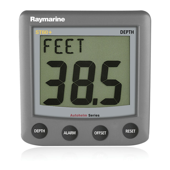
Preface Introduction Preface Thank you for purchasing a Raymarine product. We are sure your ST60+ instrument will give you many years of trouble-free operation. This handbook describes how to install and use the Raymarine ST60+ Depth instrument. This instrument provides accurate depth information, in either feet, meters or fathoms, on a high quality Liquid Crystal Display (LCD). -
Page 10: Stand Alone Operation
81262_2.book Page viii Friday, November 11, 2005 11:11 AM viii ST60+ Depth Instrument Owner’s Handbook directly connected to a transducer but displays information provided by other equipment in the SeaTalk network. The ST60+ Depth instrument can fulfil both master and repeater roles. Stand alone operation In Stand alone operation, the ST60+ Depth instrument is connected only to the relevant transducer and does not display information from, or provide... -
Page 11: Parts Supplied
81262_2.book Page ix Friday, November 11, 2005 11:11 AM Preface Parts supplied Unpack your ST60+ instrument and check that the following items are present: • Item 1,ST60+ Depth instrument with standard bezel for surface mounting. • Item 2, Fixing studs (2). •... - Page 12 81262_2.book Page x Friday, November 11, 2005 11:11 AM ST60+ Depth Instrument Owner’s Handbook DEPTH RESET ALARM OFFSET ST60+ Depth ST60+ Instrument Depth Instrument Owner's Handbook ST60+ DEPTH DEPTH RESET ALARM OFFSET Quick Start Guide...
-
Page 13: Chapter 1: Operation
81262_2.book Page 1 Friday, November 11, 2005 11:11 AM Chapter 1: Operation 1.1 Getting started This handbook describes how to operate, maintain and install the Raymarine ST60+ Depth instrument. Your ST60+ Depth instrument provides depth information, plus maximum and minimum depth alarms. -
Page 14: Operating With Fishfinder Products
81262_2.book Page 2 Friday, November 11, 2005 11:11 AM ST60+ Depth Instrument Owner’s Handbook You can reset the MIN and MAX values by pressing the reset button for 3 seconds. Operating with fishfinder products Depth information is normally obtained from the Depth transducer, fitted as part of the ST60+ Depth system. -
Page 15: Alarms
81262_2.book Page 3 Friday, November 11, 2005 11:11 AM Chapter 1: Operation The screens show the maximum/minimum depth since the last reset, but time out to the current depth screen if no user action occurs for 8 seconds. Alarms An alarm condition occurs if: •... -
Page 16: Depth Offsets
81262_2.book Page 4 Friday, November 11, 2005 11:11 AM ST60+ Depth Instrument Owner’s Handbook When the instrument is operating as a master, you can check the alarm levels and Depth alarms if necessary set them up (see flow chart). To do this, use the alarm button to select the required alarm level, then: •... -
Page 17: Contrast
81262_2.book Page 5 Friday, November 11, 2005 11:11 AM Chapter 1: Operation 3. Press any other button to leave the illumination-adjust mode. Note: The display will time out to normal operation 7 seconds after the last button press. Contrast To adjust the display contrast: 1. -
Page 18: St60+ Depth Instrument Owner's Handbook
81262_2.book Page 6 Friday, November 11, 2005 11:11 AM ST60+ Depth Instrument Owner’s Handbook... -
Page 19: Chapter 2: Maintenance & Troubleshooting
Chapter 2: Maintenance & Troubleshooting 2.1 Maintenance Servicing and safety • Raymarine equipment should be serviced only by authorised Raymarine ser- vice technicians. They will ensure that servicing procedures and replacement parts used will not affect performance. There are no user-serviceable parts in any Raymarine product. -
Page 20: Cabling
Fixing faults All Raymarine products are subjected to comprehensive test and quality assurance programmes prior to packing and shipping. However, if a fault occurs, the following table may help to identify and rectify the problem. -
Page 21: Technical Support
Please visit the Customer Support area of our web site at: www.raymarine.com As well as providing a comprehensive Frequently Asked Questions section and servicing information, the web site gives e-mail access to the Raymarine Technical Support Department and a details of the locations of Raymarine agents, worldwide. - Page 22 81262_2.book Page 10 Friday, November 11, 2005 11:11 AM ST60+ Depth Instrument Owner’s Handbook...
-
Page 23: Chapter 3: Installation
The actual type of transducer depends on the type of hull in which it is to be installed. For advice, or further information regarding the installation of this equipment, please contact the Raymarine Product Support Department or your own National Distributor. 3.1 Planning your installation... - Page 24 M78719 Retractable through hull Other transducer types are also available for specific requirements. For further details, contact your local Raymarine dealer. For accurate depth readings the transducer should be sited within the clear water flow areas indicated by the shaded areas in the following diagram.
-
Page 25: Instrument
81262_2.book Page 13 Friday, November 11, 2005 11:11 AM Chapter 3: Installation • Be as near as possible to the center line of the vessel. • Be clear of other through-hull fittings or projections. • Have sufficient clearance inside the hull to fit the nut. •... -
Page 26: Emc Installation Guidelines
ST60+ instrument dimensions D8146-1 EMC installation guidelines All Raymarine equipment and accessories are designed to the best industry standards for use in the recreational marine environment. Their design and manufacture conforms to the appropriate Electromagnetic Compatibility (EMC) standards, but correct installation is required to ensure that performance is not compromised. -
Page 27: Suppression Ferrites
Raymarine equipment. Always use the ferrites supplied by Raymarine. D3548-6 Connections to other equipment If your Raymarine equipment is to be connected to other equipment using a cable not supplied by Raymarine, a suppression ferrite MUST always be attached to the cable near the Raymarine unit. -
Page 28: Procedures
81262_2.book Page 16 Friday, November 11, 2005 11:11 AM ST60+ Depth Instrument Owner’s Handbook 3.2 Procedures As it is not practical to describe procedures for all possible installation scenarios, the procedures given here describe the broad requirements for installing depth transducers and the ST60+ Depth instrument. -
Page 29: Flush Mounting
81262_2.book Page 17 Friday, November 11, 2005 11:11 AM Chapter 3: Installation 4. Cut out the clearance hole (3) then remove the template. 5. Peel off the protective sheet from the self-adhesive gasket (4) then stick the gasket into position on the rear of the instrument. Surface mounting 6. - Page 30 81262_2.book Page 18 Friday, November 11, 2005 11:11 AM ST60+ Depth Instrument Owner’s Handbook Fitting the flush mount bezel 3. Referring to the illustration, insert the panel seal (8) in the corresponding recess on the back of the flush mount bezel (7). 4.
-
Page 31: Caution: Use The Correct Screws
81262_2.book Page 19 Friday, November 11, 2005 11:11 AM Chapter 3: Installation 5. Place the keypad seal (9) in position on the keypad (i.e. so that the holes in the seal accept the appropriate keypad buttons). 6. Place the assembled flush mount bezel and panel seal, in position on the instrument, so that the rubber keys are correctly located in the holes on the bezel, then clip the bezel and instrument together. -
Page 32: Bracket Mounting
81262_2.book Page 20 Friday, November 11, 2005 11:11 AM ST60+ Depth Instrument Owner’s Handbook 2. Ensure that: • The panel on which you intend to mount the instrument is between 0.12 in (3 mm) and 0.78 in (20 mm) thickness. •... -
Page 33: Fitting Transducer
81262_2.book Page 21 Friday, November 11, 2005 11:11 AM Chapter 3: Installation Fitting transducer The ST60+ Depth instrument is supplied, with a through-hull depth transducer. The depth transducer is supplied with detailed instructions for installation and maintenance. Before attempting to install the depth transducer, read these Site requirements instructions and the for transducers described in this Chapter. -
Page 34: Connecting The Instrument
Where a SeaTalk system includes an autopilot, the power for the system is provided by the autopilot. A range of Raymarine SeaTalk extension cables is available to connect separated instruments. These cables are supplied with a SeaTalk connector fitted to each end. -
Page 35: Power Supply Connections
81262_2.book Page 23 Friday, November 11, 2005 11:11 AM Chapter 3: Installation SeaTalk cable SeaTalk cable Black Blue Screen Cable from transducer Connections to ST60+ Depth instrument Power supply connections CAUTION: Protect the power supply Ensure that the 12 V power supply for the instrument is protected by a suitably rated fuse or protective circuit breaker. - Page 36 81262_2.book Page 24 Friday, November 11, 2005 11:11 AM ST60+ Depth Instrument Owner’s Handbook 5 A fused, 12 V dc supply (typically provided by autopilot) Screen Instruments 5 to 16 Screen SeaTalk power connections D4311-1 Stand alone instruments Stand-alone instruments are not connected to SeaTalk and therefore need to be connected to an alternative 12 V power source.
-
Page 37: Switching On
81262_2.book Page 25 Friday, November 11, 2005 11:11 AM Chapter 3: Installation 3.3 Switching on Switch on the power to your ST60+ instrument. When the power is on, you can use the depth button to switch the instrument on and off as described in Chapter 1, Operation Chapter 1, Operation Use the procedures in... - Page 38 81262_2.book Page 26 Friday, November 11, 2005 11:11 AM ST60+ Depth Instrument Owner’s Handbook...
-
Page 39: Chapter 4: Calibration
81262_2.book Page 27 Friday, November 11, 2005 11:11 AM Chapter 4: Calibration 4.1 Introduction The ST60+ Depth instrument is set up with factory-programmed default settings, so in order to optimise the performance of the instrument on board a particular vessel, the procedures in this Chapter must be carried out immediately after the completion of installation, and before the equipment is used for navigational purposes. -
Page 40: Depth Offset
81262_2.book Page 28 Friday, November 11, 2005 11:11 AM ST60+ Depth Instrument Owner’s Handbook Hold down depth alarm for approximately 2 seconds Entry screen depth Depth units depth depth Pop-up Depth At each screen use pilot offset either offset reset to set the required values Shallow alarm depth... -
Page 41: Setting Offset Values
81262_2.book Page 29 Friday, November 11, 2005 11:11 AM Chapter 4: Calibration OFFSET KEEL (+ve offset (offset value (-ve offset values) of 0.0) values) Depth offsets D4352-1 The legend at the top of the Depth offset screen reflects the value you set up, i.e. W/L for positive offsets, KEEL for negative offsets and OFFSET for zero offset. -
Page 42: Shallow Alarm Lock
81262_2.book Page 30 Friday, November 11, 2005 11:11 AM ST60+ Depth Instrument Owner’s Handbook Shallow alarm lock When set to On, the shallow alarm lock prevents inadvertent alteration to the shallow depth alarm setting. The procedure for setting alarm level levels is given in Chapter 1, Operation. Note: Pop-up pilot Switches the pop-up pilot function on and off. -
Page 43: Leaving Intermediate Calibration
81262_2.book Page 31 Friday, November 11, 2005 11:11 AM Chapter 4: Calibration 3. Press the offset and reset buttons simultaneously again, to leave the adjust mode. Note: If a fishfinder is connected to the same SeaTalk system as your ST60+ Depth instru- ment and is switched on, all ST60+ Depth instruments in the system will display fishfinder depth information from SeaTalk. -
Page 44: Response Settings
81262_2.book Page 32 Friday, November 11, 2005 11:11 AM ST60+ Depth Instrument Owner’s Handbook Hold down depth alarm for approximately 12 seconds Entry screen offset reset to set required values offset reset Depth Calibration response on/off depth depth depth Factory Boat show defaults mode... -
Page 45: Boat Show Mode
81262_2.book Page 33 Friday, November 11, 2005 11:11 AM Chapter 4: Calibration Boat show mode CAUTION: Do NOT enable Boat Show Mode Do NOT enable Boat Show Mode. This must be used only for demonstration purposes. Ensure that the Boatshow Mode Use is set to OFF . If necessary, use the offset or reset button to achieve this. - Page 46 81262_2.book Page 34 Friday, November 11, 2005 11:11 AM ST60+ Depth Instrument Owner’s Handbook...
-
Page 47: Glossary
81262_2.book Page 35 Friday, November 11, 2005 11:11 AM Glossary Apparent Average Apparent Wind Angle (relative to the vessel) Apparent Wind Speed Bearing To Waypoint Course Made Good Course Over Ground Distance Made Good Distance To Waypoint Electro Magnetic Compatibility Estimated Time of Arrival Global Positioning System Heading... - Page 48 Miles per hour Nautical mile(s) Response The sensitivity of an instrument, to data changes. Radio Frequency SeaTalk Raymarine proprietary communication system which links products, to provide a single, integrated system sharing power and data. Statute mile(s) Speed Over Ground Speed True Time To Go True Wind Angle relative to the vessel, taking into account the speed of the vessel.
-
Page 49: Index
81262_2.book Page 37 Friday, November 11, 2005 11:11 AM Index – Alarms Maximum depth Minimum depth Mounting options (instrument) viii Backlighting adjustment Boat show mode – Parts supplied Pop-up pilot Calibration requirement Power supply Cleaning SeaTalk systems Condensation stand alone instrument Contrast adjustment Product disposal Current depth... - Page 50 81262_2.book Page 38 Friday, November 11, 2005 11:11 AM ST60+ Depth Instrument Owner’s Handbook...
- Page 51 81262_2.book Page 39 Friday, November 11, 2005 11:11 AM diameter in 2 positions Template Drill hole, 3/16 in (5 mm) SURFACE MOUNT diameter in 2 positions Template Cut hole 3.54 in (90 mm) diameter Cut hole 3.54 in (90 mm) diameter Remove material from shaded areas only...
- Page 52 81262_2.book Page 40 Friday, November 11, 2005 11:11 AM...
-
Page 53: Control Unit
81262_2.book Page 41 Friday, November 11, 2005 11:11 AM Control Unit Drill hole, 1/4 in (6.5 mm) FLUSH MOUNT diameter in 4 positions Template Remove material from shaded area only 4.3 in (109 mm) Instrument edge Sun cover edge FLUSH MOUNT template for ST60+ Instruments... - Page 54 81262_2.book Page 42 Friday, November 11, 2005 11:11 AM...
-
Page 55: Limited Warranty
For any Raymarine product or system that (i) has been installed on your vessel by a Raymarine-certified service agent or by a Raymarine OEM, and (ii) has a MSRP equal to or greater than USD $2,500, you are eligible to receive warranty service by a Raymarine certified service agent on-board your vessel (‘On Board Warranty Service’) for a period of 12... - Page 56 Other conditions This Warranty is fully transferable provided that you furnish the original proof of purchase to Raymarine or, in the case of On Board Warranty Service, to a Raymarine-certified service agent. This Warranty is void if the label bearing the serial number has been removed or defaced.
- Page 57 2 years (24 months), subject to the limits contained in this warranty document. In the case of a product installed, by a Raymarine certified OEM installer, on a new boat prior to the sale of the boat to a customer, the 2-year period will begin on the date of the sale of the boat to the customer.
- Page 58 Raymarine Service Agent) at no further cost and promptly returned to the customer. 3.3 In cases where the customer is making a warranty claim and the product has been installed by a Raymarine certified installer, (boat builder, installer, dealer etc.) i.e. Onboard warranty, the nearest Raymarine approved service agent should be contacted and onboard service requested (which will be subject to the limits referred to in paragraph 4.12 below).
- Page 59 81262_2.book Page V Friday, November 11, 2005 11:11 AM Raymarine World Wide Warranty 4.10 If repairs are necessary under the warranty, the affected product must be forwarded to a Raymarine facility or a Raymarine approved service agent, at the owner’s expense.
- Page 60 Raymarine Technical Support Raymarine Technical Support +44 (0) 23 9271 4713 1-800-539-5539 or, +1 603-881-5200 Product Repair and Service Product Repair and Service Raymarine Product Repair Center Raymarine plc Anchorage Park 21 Manchester Street, Portsmouth Merrimack, PO3 5TD NH 03054-4801...
Need help?
Do you have a question about the ST60+ and is the answer not in the manual?
Questions and answers