Raymarine ST60+ Owner's Handbook Manual
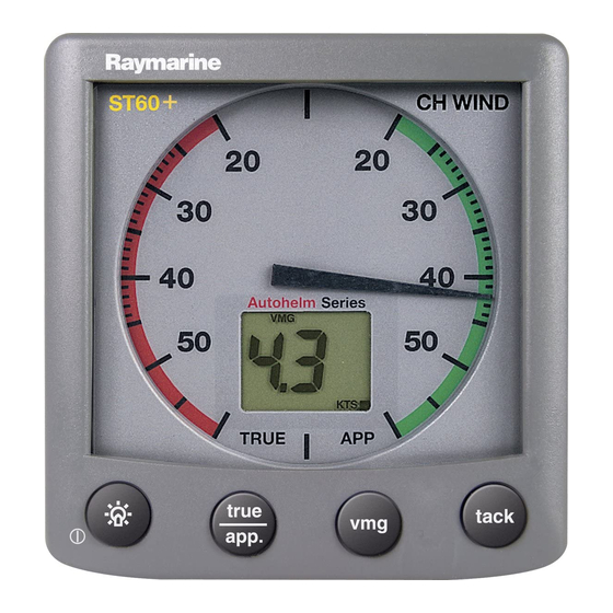
Club house wind instrument
Hide thumbs
Also See for ST60+:
- Owner's handbook manual (70 pages) ,
- Quick start manual (2 pages) ,
- Owner's handbook manual (62 pages)

Related Manuals for Raymarine ST60+


Summary of Contents for Raymarine ST60+
- Page 1 ST60+ Club House Wind Instrument Owner’s Handbook Document reference: 81267-1 Date: December 2005...
- Page 2 Raymarine, ST60+ and SeaTalk are trademarks of Raymarine UK Limited © Handbook contents copyright Raymarine UK Limited 2005...
-
Page 3: Safety Notices
Handbook information To the best of our knowledge, the information in this handbook was correct when it went to press. However, Raymarine cannot accept liability for any inaccuracies or omissions it may contain. In addition, our policy of continuous product improvement may change specifications without notice. -
Page 4: Product Disposal
The WEEE Directive requires the recycling of waste electrical and electronic equipment. Whilst the WEEE Directive does not apply to some of Raymarine's products, we support its policy and ask you to be aware of how to dispose of this product. -
Page 5: Table Of Contents
Preface Contents Preface Important information ... i Safety notices ... i WARNING: Product installation & operation... i WARNING: Electrical safety ... i WARNING: Instrument usage ... i EMC conformance ... i Handbook information ... i Product disposal ... ii Contents... iii Introduction ... - Page 6 Suppression ferrites... 9 Connections to other equipment... 10 2.2 Installation procedure ...10 CAUTION: Maintain structural safety ...10 Unpacking...10 Fitting the instruments ...10 Surface mounting... 11 Flush Mounting ... 12 CAUTION: Use the correct screws...13 Bracket Mounting Kit ... 14 Connections at the instrument...15 Power supply connections...
-
Page 7: Introduction
Thank you for purchasing a Raymarine product. We are sure your ST60+ instrument will give you many years of trouble-free operation. This handbook describes how to install and use the Raymarine ST60+ Club House Wind instrument, which is intended for use ashore (e.g. in clubhouses or homes) to show local wind conditions. -
Page 8: Parts Supplied
Parts supplied Unpack your ST60+ instrument and check that the following items are present: • Item 1, ST60+ Club House Wind instrument, fitted with standard bezel for sur- face mounting. • Item 2, Fixing studs (2). • Item 3, Thumb nuts (2). •... -
Page 9: Chapter 1: Operation & Maintenance
Chapter 1: Operation & Maintenance 1.1 Getting started This handbook describes how to operate, maintain and install the Raymarine ST60+ Club House Wind instrument. This instrument shows the wind speed and direction. CAUTION: Calibration requirement To ensure this product performs at its best, you MUST calibrate it... -
Page 10: Digital Display
Digital display The digital display normally shows the wind speed in either knots or meters per second. You can use the operation flow chart), displayed as follows: • Beaufort wind speed. • Maximum wind speed. • Maximum wind speed alarm. •... -
Page 11: Maximum Wind Speed
Chapter 1: Operation & Maintenance Maximum wind speed The maximum wind speed is reset at power up and can also be reset manually by pressing the > button for 3 seconds. Wind speed alarms An alarm condition occurs when the wind speed either exceeds the maximum wind speed alarm level or falls below the minimum wind speed alarm level. -
Page 12: Maintenance
1.3 Maintenance Servicing and safety • Raymarine equipment should be serviced only by authorized Raymarine ser- vice technicians. They will ensure that service procedures and replacement parts used will not affect performance. There are no user serviceable parts in any Raymarine product. -
Page 13: Troubleshooting
Please visit the Customer Support area of our web site at: www.raymarine.com As well as providing a comprehensive Frequently Asked Questions section and servicing information, the web site gives e-mail access to the Raymarine Technical Support Department and a details of the locations of Raymarine agents, worldwide. -
Page 14: Help Us To Help You
Help us to help you When requesting service, please quote the following product information: • Equipment type. • Model number. • Serial number. • Software issue number. To find out the software version number of your ST60+ Club House Wind instrument: 1. -
Page 15: Chapter 2: Installation
Wind Vane transducer. The transducer is connected to the rear of the instrument. For advice, or further information regarding the installation of this equipment, please contact the Raymarine Product Support Department or your own National Distributor. 2.1 Planning your installation... -
Page 16: Instrument
There must also be a viable route for the transducer cable to be routed to the instrument. As you will need to manually rotate the Wine Vane as part of the linearization pro- Note: cedure, do not actually fit it in position yet. Instrument CAUTION: Keep the rear of the instrument dry Keep the rear of instrument dry. -
Page 17: Emc Installation Guidelines
• Raymarine specified cables are used. Cutting and rejoining these cables can compromise EMC performance and must be avoided unless doing so is detailed in the installation manual. -
Page 18: Connections To Other Equipment
Connections to other equipment If your Raymarine equipment is to be connected to other equipment using a cable not supplied by Raymarine, a suppression ferrite MUST always be attached to the cable near the Raymarine unit. 2.2 Installation procedure As it is not practical to describe procedures for all possible installation scenarios, the procedures given here describe the broad requirements for installing a Wind Vane and ST60+ Club House Wind instrument. -
Page 19: Surface Mounting
Chapter 2: Installation ST60+ instruments can also be mounted behind a suitably prepared panel, so that just the instrument dial and buttons are visible. Surface mounting To surface mount your ST60+ instrument (see the 1. Ensure that: • The selected location is clean, smooth and flat. -
Page 20: Flush Mounting
Flush Mounting The Flush Mounting Kit uses a low-profile bezel to reduce the fitted profile of the instrument, to approximately 0.25 in (6 mm) above the panel fascia. Fitting the flush mount bezel In order to flush-mount your ST60+ instrument, you must first replace the standard bezel with the flush mount bezel as follows: 1. -
Page 21: Caution: Use The Correct Screws
Chapter 2: Installation CAUTION: Use the correct screws It is essential that only screws of the correct size are used to secure the instrument to the bezel. Failure to observe this caution could result in damage to both the instrument and the bezel. 7. -
Page 22: Bracket Mounting Kit
• There is sufficient space behind the location to accommodate the rear of the instrument and connectors. 3. Apply the flush mount template (supplied at the rear of this handbook) to the selected location and mark out the aperture into which the assembled instru- ment and bezel will sit. -
Page 23: Connections At The Instrument
Chapter 2: Installation Although this provides a useful alternative method for securing your instrument, it is only suitable for use in positions where the instrument will not be exposed to water. To bracket mount your ST60+ instrument, do so in accordance with the Control Unit Mounting Bracket Instruction Sheet. -
Page 24: Linearization
12 V dc supply Power connections for stand-alone instrument 3. If the cable has not already been trimmed at the power supply end: i. Cut the cable to length and trim back an appropriate amount of the outer sheath. ii. Cut back and insulate the yellow wire. 4. - Page 25 Chapter 2: Installation The wind vane base must be horizontal. If necessary, make up a suitable packing piece to provide a horizontal mounting surface. You can fit your wind vane so the cable leaves the wind vane base either from the rear (option A), or from underneath (option B), as in the following cable options illustration.
-
Page 26: Running Transducer Cable
Fixing screws 3. Referring to the rectly for the option you are using, then secure the wind vane base, using the two self-tapping fixing screws. 4. Insert the wind vane arm into the wind vane base connector and tighten the locking ring securely by hand. -
Page 27: Switching On
Chapter 2: Installation The Wind Vane is supplied with sufficient cable already connected, to run from the mounted position to the ST60+ Club House Wind instrument. The manner in which you run the cable will depend on the locations of the transducer and instrument. -
Page 28: Caution: Calibration Requirement
CAUTION: Calibration requirement To ensure this product performs at its best, you MUST calibrate it before use, in accordance with the instructions in Calibration calibrated it EMC conformance Always check the installation before use to make sure that it is not affected by radio transmissions or other external electromagnetic influences. -
Page 29: Chapter 3: Calibration
Chapter 3: Calibration 3.1 Introduction The ST60+ Club House Wind instrument is set up with factory-programmed default settings, so in order to optimize performance at a particular installation, the procedures in this Chapter must be carried out immediately after the completion of installation. -
Page 30: Leaving User Calibration
Hold down Hold down Entry screen Entry screen Wind angle offset Wind angle Wind speed units Wind speed User calibration User calibration Leaving User calibration Hold down the calibration and resume normal operation. 3.3 Intermediate calibration The intermediate calibration screen enables you to check the instrument software version number. -
Page 31: Dealer Calibration
Chapter 3: Calibration 3.4 Dealer calibration The Dealer calibration procedures enable the following parameters to be set: • Wind angle and speed response. • Wind speed calibration. • Boat show mode on/off. Dealer calibration also gives access to the Factory defaults screen. This enables you to re-apply the factory settings if you want to reset the instrument to a known operating condition. - Page 32 Hold down Entry screen Wind angle response Wind speed response Wind speed TRUE go to sheet 2 Dealer calibration - sheet 1 ST60+ Club House Wind Instrument Owner’s Handbook for approximately 12 seconds Press to set required response (A1 to A15) Press to set required response (S1 to S15)
-
Page 33: Boat Show Mode
Chapter 3: Calibration from sheet 1 Boat show mode Factory defaults Hold down to exit calibration Dealer calibration - sheet 2 Boat show mode CAUTION: Do NOT enable Boat Show Mode Do NOT enable Boat Show Mode. This must be used only for demonstration purposes. - Page 34 ST60+ Club House Wind Instrument Owner’s Handbook...
-
Page 35: Glossary
Glossary Apparent Average Apparent Wind Angle (relative to the vessel) Apparent Wind Speed Bearing To Waypoint Course Made Good Course Over Ground Distance Made Good Distance To Waypoint Electro Magnetic Compatibility Estimated Time of Arrival Global Positioning System Heading Kilometer(s) Kilometers per hour Knot(s) Latitude... - Page 36 Miles per hour Nautical mile(s) Response The sensitivity of an instrument, to data changes. Radio Frequency SeaTalk Raymarine proprietary communication system which links products, to provide a single, integrated system sharing power and data. Statute mile(s) Speed Over Ground Speed True Time To Go True Wind Angle relative to the vessel, taking into account the speed of the vessel.
-
Page 37: Index
Index Alarm canceling setting conditions Backlighting adjustment Boat show mode Calibration requirement Cleaning Condensation Dealer calibration Display setup Displayed information digital display pointer Disposing of the product EMC information Factory defaults Help lines Installing instrument bracket mounting flush mounting power supply connections requirements signal connections surface mounting... - Page 38 ST60+ Club House Wind Instrument Owner’s Handbook...
- Page 39 Drill hole, 3/16 in (5 mm) SURFACE MOUNT diameter in 2 positions Template Cut hole 3.54 in (90 mm) diameter Remove material from shaded areas only Sun cover edge Instrument edge 1.185 in (30.1 mm) 1.18 in (30.0 mm) SURFACE MOUNT template for ST60+ Instruments...
-
Page 41: Control Unit
Control Unit FLUSH MOUNT Template Remove material from shaded area only Instrument edge FLUSH MOUNT template for ST60+ Instruments Drill hole, 1/4 in (6.5 mm) diameter in 4 positions 4.3 in (109 mm) Sun cover edge... - Page 43 50 mm Drill hole, 4 mm 34.5 mm diameter 27.5 mm 7 mm Center Front Line 10 mm Drill hole, 4 mm If cable is to leave base from diameter underneath, drill hole, 8 mm diameter (not required if cable to exit from rear) Wind vane drilling template D6955-1...
Need help?
Do you have a question about the ST60+ and is the answer not in the manual?
Questions and answers