tau speed 2 User Manual
Automations for sliding gates
Hide thumbs
Also See for speed 2:
- Use and maintenance manual (57 pages) ,
- Use and maintenance manual (17 pages)

Related Manuals for tau speed 2


Summary of Contents for tau speed 2
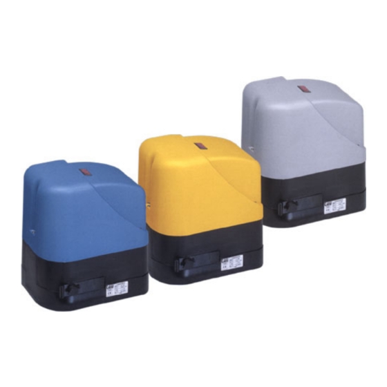
- Page 1 AUTOMATIONS FOR SLIDING GATES AUTOMATIZACIONES PARA PORTONES CORREDIZOS SPEED 2 - 5 - 8 USE AND MAINTENANCE MANUAL MANUAL DE USO Y MANTENIMIENTO...
- Page 2 Cuando abra el embalaje, compruebe la integridad del producto. No deje que los niños jueguen en zonas donde exista peligro de ahogarse. Reciclar los materiales según las normativas vigentes. TECHNICAL FEATURES SPEED 2 SPEED 5 SPEED 8 Power...
-
Page 3: Considerations Prior To Installation
Art.P 400CNR Nylon rack; Art.P-400CPS Foundation counter plate complete with screws Art.P-350... Geared motor mod. Speed 2 - 5 - 8 including: Art.S-350F300140 nr. 2 end limit-sliding blocks (only for SPEED 5-8) MATERIALES PARA LAINSTALACION Art.P 400CNR Cremallera de Nylon;... -
Page 4: Preparing The Base
FINDING THE SITE LOCALIZACION DE LA UBICACION Choose a position that is identical to the dotted area. Elegir una posicion análoga al area punteada. PREPARING THE BASE PREPARACION DE LA BASE Dig comfortably wide foundations, at least 15 cm deep. Protect the cables with a sheath. -
Page 5: Fijación Del Motorreductor
ANCHORING THE FOUNDATION COUNTER PLATES FIJACION DE LA CONTRAPLACA DE CIMENTACION 1.Once finished with the ditch, prepare the fundation counterplate by bending the clamps of the plate (see Fig. below) by the same spot where the cones are jointed to fasten the operator with screws. Fill the ditch with cement; the counterplate has to be completely leveled at 3/8"... -
Page 6: Fijación De La Cremallera
Tighten the screws (as shown in fig G) on both sides of the geared motor. Carry all cables across the holes obtained from the base of the foundation counter plate. Apretar los tornillos (tal como se indica en la fig.G1 - G2 ) en ambos lados del motorreductor. Pasar todos los cables a través de los agujeros existentes en la base de la contraplaca de cimentación. - Page 7 USE OF MANUAL UNLOCKING UTILIZACIÓN DEL DESBLOQUEO MANUAL ADJUST THE MECHANICAL FRICTION CLUTCH (SPEED 2 - 5) AND THE ELECTRIC FRICTION CLUTCH (SPEED 8) AJUSTE DEL EMBRAGUE ELÉCTRICO (SPEED 2 - 5) Y MECÁNICO (SPEED 8)
- Page 8 SPEED 5 SPEED 8 Fig. P Fig. Q The mechanical friction clutch of SPEED 5 can be modified with a screwdriver regulating the RCM trimmer as shown in Fig. P; on the contrary the mechanical friction clutch of SPEED 8 can be regulated manually with a key included in the kit of the geared motor as shown in fig Q.
- Page 9 CONEXIONES ELÉCTRICAS (SPEED 2 - 5 - 8) To connect remove the casing from the geared motor, the electrical components stand and only for SPEED 2 the cover of transformer, Fig. R. Carry all cables across the holes obtained from the foundation' s base counter plate and across the inferior...
- Page 10 Fig. U...
- Page 11 Fig. V...
-
Page 12: Terminal Board Connections
TERMINAL BOARD CONNECTIONS For Slider Cross Speed 2 MEC-10 110 V Terminals inside transformer housing. 1 – 2 12V DC supply terminal 1 + terminal 2 – 3 – 4 12V DC 6Ah dry battery input terminals 3 + terminal 4 - This battery guarantees power to panel for 24 hours with panel in waiting state or 20 minutes with motor running (app. - Page 13 7 & 8 NOT IN USE 9 & 10 ELECTRONIC FRICTION ADJUSTMENT The system is highly sensitive to any variation in speed of travel due to any obstructions. Adjust as follows: OFF OFF Maximum ON OFF Medium maximum OFF ON Medium minimum ON ON Minimum...
- Page 14 TERMINAL BOARD CONNECTIONS For Slider Cross-Speed 5 – Speed 8 1 – 2 110 V AC 50 Hz Power Supply 5 – 6 – 7 Motor Terminals: 5 – common, 6 – opening, 7 – closing. Capacitor between terminals 6 – 3 –...
- Page 15 Los motorreductores SPEED 2-5-8 han sido proyectados para mover la verjas de deslizamiento horizontal con hojas que tengan un peso máximo de 400 kg (para el mod. Speed 2), 800 Kg (para el mod. Speed 5) y 800 Kg (para el mod. Speed 8).
-
Page 16: Maintenance
• Mover la verja sólo cuando sea completamente visible; • Mantenerse fuera del radio de acción de la verja, si ésta se halla en movimiento, esperar hasta que se haya detenido; • No dejar que niños o animales jueguen cerca de la verja; •...
Need help?
Do you have a question about the speed 2 and is the answer not in the manual?
Questions and answers