Advertisement
Quick Links
INSTALLATION GUIDE
DOOR
Automation for sliding automatic door
GB - Translation of Original Instructions
Via Enrico Fermi, 43 - 36066 Sandrigo (VI) Italia
Tel +39 0444 750190 - Fax +39 0444 750376 - info@tauitalia.com - www.tauitalia.com
DOOR Series - English
1
Advertisement

Related Manuals for tau DOOR


Summary of Contents for tau DOOR
-
Page 1: Installation Guide
INSTALLATION GUIDE DOOR Automation for sliding automatic door GB - Translation of Original Instructions Via Enrico Fermi, 43 - 36066 Sandrigo (VI) Italia Tel +39 0444 750190 - Fax +39 0444 750376 - info@tauitalia.com - www.tauitalia.com DOOR Series - English... -
Page 2: General Safety Recommendations
As established by the EU commission, automated pedestrian closing systems are governed by the machine directive (2006/48/EC). This latter specifies that the installer who fits a driving system on a door or gate has the same obligations as the manufacturer of the machine. - Page 3 12.4_ CONNECTING THE RECEIVER AND TRANSMITTER CAPSULES pag. 13 12.5_ ADJUSTING THE CAPSULE SENSITIVITY pag. 13 12.6_ OPERATING FAULTS pag. 13 12.7_ DOOR STOP WITH STOP BUTTON pag. 14 THE DOORPROG SELECTOR SWITCH pag. 15 DOORBATT BATTERY OPERATED OPENING DEVICE pag. 16 ADJUSTING THE AUTOMATISM pag.
- Page 4 šˆ“–• ‡Œ lockR minidip sQ minidip sR „–˜ˆ †‹Œ›‡ˆ „–ˆ˜š›˜„ †‹Œ›™›˜„ „–ˆ˜š›˜„ Œ”œˆ˜”„’ˆ –„›™„ ANTA FISSA ANTA FISSA FIXED WING FIXED WING DOUBLE LEAF VANTAIL FIXE VANTAIL FIXE FEST TÜRFLÜGEL FEST TÜRFLÜGEL HOJA FIJA HOJA FIJA DOOR Series - English...
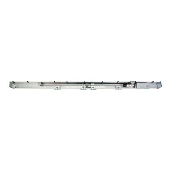
- Page 5 4 Aluminium sliding track 5 Sides 6 Gearmotor 7 Encoder 8 Electronic equipment with transformer 9 Battery 10 Snub pulley 11 Brake bumper 12 Cable guide 13 Timing belt 14 Electric block 15 Carriages fig. 3 DOOR Series - English...
- Page 6 LEAF DIMENSIONS AND STANDARD REFERENCES For proper door operation, the carriage centre distances and the distance between the carriages and the end of the door frame must be observed, as shown in figure 6. Refer also to figures 7, 8, 9 and 10 regarding the safety clearance regulations to be observed.
- Page 7 Move the wings to the closed position by hand and make sure that the mobile part A of the electro-lock connects the two locking brackets B on the carriages (there is only one bracket if the door has one wing). If it fails to connect, unscrew the screws C that fix the electro- lock and move everything to the position in which the locking brackets are able to couple with mobile part A.
- Page 8 The cable terminal must be set just after the lower fastening screw (clockwise) when the knob is inserted DOOR Series - English...
- Page 9 Lastly, check to make sure that when the release mechani- sm is operated, the solenoid’s core is raised and able to free the door, and that when the release mechanism is set back to the NOT RELEASED position, the solenoid’s core is free to move up and down without impediments or obstructions of any type.
- Page 10 J8 CONNECTOR (operation 2): DOORIM module activation (paragraph 18). F1 FUSE: 5A, protection of 230 Vac power supply line. F2 FUSE: 10A, protection of motor power supply line. F3 FUSE: 4A, protection of logic card 12V power supply. DOOR Series - English...
- Page 11 14 = PEDESTRIAN input N.O. a) It opens the door approx. 90 cm for passage in all QQ QR QS QT QU conditions, except when the system is in night locking mode (the pedestrian opening distance can be modified only from the DOORPROG selector switch).
- Page 12 FT2/FR2) for closing safety, while the third pair (FT3/FR3) can be set to one of the following functions using switches 5 and 8 of DIP S2 (see TABLE 2): closing safety photocell, door crash sensor if a crash panic system is used (in this case the power supply to the motor is disconnected) or as an opening mode input.
- Page 13 A STOP button with N.C. contact can be connected between terminals FT3 and FR3 in order to stop the movement of the door. In order to exploit this possibility it is necessary to enable FT3/FR3 on the photocell card and to make it operational as a door crash sensor (see TABLES 1 and 2).
- Page 14 THE DOOR PROG SELECTOR SWITCH Connect the digital selector DOORPROG to connector M1 of the control unit “Door” (paragraph 11). Exhausted battery and power failure signals Input status signals Work program selection Reduced opening selection Free functions Locked functions The key is used to block the selected functions. The required program can be set with the SET button in the FREE FUNCTIONS mode.
- Page 15 If you wish to add a new automated system to your house, contact your fi tter and we at Tau to have the advice of a specialist, the most developed products on the market, best operation and maximum automation compatibility.
- Page 16 Firma manutentore Firma utilizzatore Data Descrizione intervento Parti sostituite Fitter’s signature User’s signature Date Description of job Parts replaced Unterschrift des Unterschrift des Datum Beschreibung des Eingriffs Ersetzte teile Wartungsmannes Benutzers Date Description intervention Parties remplacées Signature réparateur Signature utilisateur Fecha Descripción del trabajo Piezas sustituidas...
- Page 17 Firma manutentore Firma utilizzatore Data Descrizione intervento Parti sostituite Fitter’s signature User’s signature Date Description of job Parts replaced Unterschrift des Unterschrift des Datum Beschreibung des Eingriffs Ersetzte teile Wartungsmannes Benutzers Date Description intervention Parties remplacées Signature réparateur Signature utilisateur Fecha Descripción del trabajo Piezas sustituidas...
- Page 18 Firma manutentore Firma utilizzatore Data Descrizione intervento Parti sostituite Fitter’s signature User’s signature Date Description of job Parts replaced Unterschrift des Unterschrift des Datum Beschreibung des Eingriffs Ersetzte teile Wartungsmannes Benutzers Date Description intervention Parties remplacées Signature réparateur Signature utilisateur Fecha Descripción del trabajo Piezas sustituidas...
- Page 19 ● In case of replacement, use always original batteries (18V, 600mAh). ● The replacement must be carried out by qualified personnel. ● Batteries must be removed before its disposal. ● Batteries contain pollutants, disposal must be performed complying with local rules and regulations. DOOR Series - English...
- Page 20 If the automation is a RIGHT-HAND OPENING LEAF, set DIP4 of S2 at ON, otherwise leave it in the OFF position. If the door is a fire dor and a smoke sensor is connected to the INTERLOCK input, set DIP 7 of S2 ON, otherwise leave it OFF.
- Page 21 To RESET the control unit without disconnecting the mains power source, proceed as follows: access the programming mode with selector DOORPROG, follow steps A) to E) in section 15.3, then quit the programming mode by following steps Z1) to Z3) of section 15.3. DOOR Series - English...
- Page 22 WARNING: if the dip switch is set to OFF, in the event of a power failure the door can be opened using the emergency input BATTERY MONITORING.
- Page 23 It automatically increases the pause time if the door cannot be closed due to high traffic. The pause time is kept at a constant value with the dip-switch in the OFF position. It activates work program selection via the DOORSELF mechanical selector switch (see paragraph 17).
- Page 24 REDUCED SPEED TM10 The door moves at this speed if its direction is reversed after having covered a short dis- tance from start-up. This prevents it from moving at an excessively high speed when it nears the end of travel during the reversing phase.
- Page 25 While the first door is closing, and for 5 seconds after completion of the closing manoeuvre, the START input is ignored in order to en- able the moving door to shut completely and enable the second door to open while preventing access through the first.
- Page 26 DOOR ALWAYS OPEN = to keep the door completely open. If you start opening the door by setting the selector switch to the WINTER OPENING mode, and then immediately turn the knob to the DOOR ALWAYS OPEN position, the door will stop in the winter opening position.
- Page 27 The DOOR device has a specific function for use on fire doors. Connect a smoke sensor with N.C. Contact on the INTERLOCK input to terminal 7 to obtain forced door closing at slow speed after detection by the sensor. None of the control and safety inputs will be activated during this closing manoeuvre. To enable the function, set DIP 7 of S2 ON before making the initial setup.
- Page 28 IMPORTANT!! If the door fails to operate in the desired way after any one of the parameters in the TECHNICAL MENU has been changed and you wish to return to the original operating mode, proceed as described below: a) access the programming mode by means of the DOORPROG selector;...
- Page 29 It is advisable to have always the digital selector DOORPROG at disposal during each servicing intervention on the automatic door (even if the mechanical selector DOORSELF is physically installed), in order to display the input state through the pilot lamps and to gain access to the advanced regulations of the technical menu, which are possible only with the help of the digital selector DOORPROG.
- Page 30 GUARANTEE: GENERAL CONDITIONS TAU guarantees this product for a period of 24 months from the date of purchase (as proved by the sales document, receipt or invoice). This guarantee covers the repair or replacement at TAU’s expense (ex-works TAU: packing and transport at the customer’s expense) of parts that TAU recognises as being faulty as regards workmanship or materials.
- Page 31 Commercial name: AUTOMATIC SLIDING DOOR Has been produced for incorporation on an access point (pedestrian sliding door) of for assembly with other devices used to move such an access point, to constitute a machine in accordance with the Machinery Directive 2006/42/EC.
- Page 32 Via Enrico Fermi, 43 36066 Sandrigo (VI) - Italy Tel +39 0444 750190 Fax +39 0444 750376 info@tauitalia.com www.tauitalia.com...
Need help?
Do you have a question about the DOOR and is the answer not in the manual?
Questions and answers