Rice Lake CW-90 Installation Manual
Checkweigher
Hide thumbs
Also See for CW-90:
- Technical manual (84 pages) ,
- Options installation (16 pages) ,
- Installation manual (12 pages)

Related Manuals for Rice Lake CW-90


Summary of Contents for Rice Lake CW-90
- Page 1 CW-90/90X Checkweigher Installation Manual To be the best by every measure ™ 105942...
-
Page 3: Table Of Contents
5.1 Range Mode ..............36 © 2009 Rice Lake Weighing Systems. All rights reserved. Printed in the United States of America. - Page 4 9.7 Updating CW-90/90X Firmware ........
-
Page 5: About This Manual
Ensure power is disconnected prior to installing, servicing, transporting, or storing equipment. Introduction Keypad Functions The CW-90/CW-90X is a high-speed digital weight indicator and scale base programmed to compare weight readings with predetermined tolerance limits defining an “accept” band. Function... -
Page 6: Annunciators Leds
“target” value. The When in the net weight display mode, it CW-90/CW-90X then computes the final indicates that the current net weight reading is over/under values using the target value and within +/-0.25 display divisions of the center of the over/under tolerance settings defined net zero. -
Page 7: Bar Graph Leds
Bar Graph LEDs The bar graph LEDs provide you with a fast way of determining if a container is too heavy ( ), too light OVER ), or is within an acceptable weight range ( UNDER ACCEPT ACCEPT OVER UNDER Slightly under Slightly over Moderately under... -
Page 8: Installation
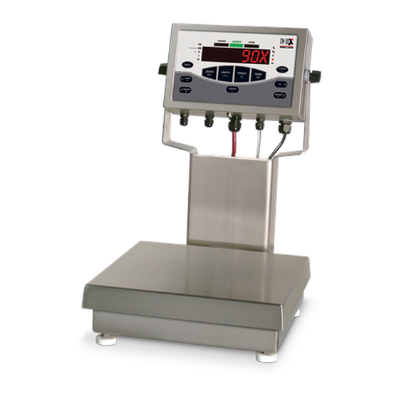
6. Attach indicator to the column with the two knobs and nylon washers provided. Position nylon washers between indicator enclosure and column mounting holes. Indicator Column Column Support Lock Washer Cap Screw 1/4-20NC x 1-3/4 Coupling Nut Lock Washer Foot Cap Screw 1/4-20NC X 3/4 Figure 2-2. Mounting column to scale platform CW-90/90X Installation Manual... -
Page 9: Leveling
AC power source. Failure to ground the base may cause static buildup and incorrect weights. Cable Grounding NOTE: The CW-90 must be installed near an easily accessible Except for the power cord, all cables routed through power outlet to allow for quick disconnect in case of emergency. -
Page 10: Serial Communications
Figure 2-4. Digital I/O lights and screw locations 20mA+ Ground Connector Signal Ground DIG I/O 1 DIG I/0 2 Table 2-3. J2 and J3 pin assignments DIG I/O 3 DIG I/O 4 Table 2-4. J4 Pin Assignments (Digital I/0) CW-90/90X Installation Manual... -
Page 11: Enclosure Reassembly
If you must remove the CPU board, use the Each option card is shipped with installation CW-90/90X following procedure: instructions specific to that card. For specific instructions on the WLAN card, refer to Section 8.0 1. Disconnect power to the indicator. Remove on page 54. - Page 12 Figure 2-5. CW-90/90X CPU board Jumper Description JP1/JP2 Jump excitation to sense. If using a 4-wire load cell cable, leave JP1 and JP2 on. If using a 6-wire load cell cable, take JP1 and JP2 off. Default is ON. JP3/JP4 Used when upgrading firmware.
-
Page 13: 2.12 Replacement Parts And Assembly Drawings
85202 Power Cord ASSY, 120VAC (1) 85203 Power Cord ASSY, 230VAC (1) 88733 Vent, Breather Sealed (1) 88734 Nut, Breather Vent (1) 107476 Bench Scale Foot 105555 Coupling Nut for Feet and Overload Stops Figure 2-6. CW-90/90X replacement parts Installation... - Page 14 107177 Table 2-6. CW-90X Load Cells Scale Capacity Load Cell Part Number 5 lb 107756 10 lb 107757 25 lb 107758 50 lb 107759 100 lb 107760 Table 2-7. CW-90 Load Cells Figure 2-7. CW-90/90X front view CW-90/90X Installation Manual...
- Page 15 Figure 2-8. CW-90/90X assembly and components Installation...
- Page 16 11.24 9.50 3.12 6.00 8.57 10.02 3.75 4.00 10.02 6.00 2.01 3.75 3.00 .281 Figure 2-9. CW-90/90X dimensions CW-90/90X Installation Manual...
-
Page 17: Configuration
OVER UNDER TARGET digit. This also applies to the CW-90, whose numeric keys can be used to insert a digit to the right of the blinking digit. Press to accept the data and return to the next menu item. ENTER NOTE: To exit Configuration and return to weighing, press the MENU key or navigate to the EXIT menu and press ENTER. -
Page 18: Audit Menu
The CW-90/90X requires the WZERO and WSPAN points to be calibrated. The linearity points are optional, but must NOT duplicate zero or span. During calibration, the ENTER key acts as a data entry confirmation key. It also acts as an EXECUTE key, and accepts the value if calibration was successful. - Page 19 CALIBR Menu Parameter Choices Description Level 2 submenus WZERO — Press ENTER and the A/D raw counts will be displayed. Press ENTER again to calibrate zero, or press MENU to cancel. “CALIBRATING, PLEASE WAIT” will be appear prior to automatically moving to WVAL. WVAL —...
-
Page 20: Setup Menu
VISIBL THRESH 30HZ 2OUT NONE BOTH 4OUT 7.5HZ NOTARE DELAY 15HZ 8OUT PBTARE 60HZ 16OUT KEYED 120HZ 32OUT 240HZ 64OUT 128OUT 480HZ 100D 960HZ 200D 250D * Not legal for trade Figure 3-5. Setup menu: Scale submenu CW-90/90X Installation Manual... - Page 21 SCALE Menu Parameter Choices Description Level 3 submenus CALIBR WZERO See Section 3.3 on page 14 for descriptions, and see Section 4.0 on page 33 for WVAL calibration procedures. WSPAN Calibration can be performed in two places within the menu: the CALIBR menu shown in WLIN Figure 3-5 is an in-depth scale setup and calibration.
- Page 22 (except for LFT parameters) now only needs to go below this value and then above it again. NOTE: If checkweighing is used, THRESH should be less than the under value or it can disable the digital I/O points from tripping. CW-90/90X Installation Manual...
- Page 23 SCALE Menu Parameter Choices Description Level 4 submenus PRIMRY UNITS Allows you to set the primary units, decimal point format, and display divisions. DECPNT DSPDIV Allows you to set the secondary units. Decimal point format and display divisions are selected automatically. Values are kg=kilogram (default);...
-
Page 24: Featur Submenu
NUMBER OVER UNDER ZERO UNITS PRINT UNLOCK UNLOCK UNLOCK UNLOCK UNLOCK UNLOCK UNLOCK UNLOCK UNLOCK LOCK LOCK LOCK LOCK LOCK LOCK LOCK LOCK LOCK *INDUST Submenu is in Section 3.4.3 on page 24. Figure 3-6. FEATUR submenu CW-90/90X Installation Manual... - Page 25 CW-90 after the password override is performed. KEYLCK OVER Disables the OVER, UNDER, ZERO, UNITS, PRINT, TARE, ID, TARGET, and/or numeric UNDER (CW-90 only) key(s). Select Lock to disable the key, and Unlock to enable the key. ZERO UNITS PRINT TARE...
- Page 26 Sets the term displayed when weighing in gross mode. Selecting BRUTTO replaces the Gross BRUTTO annunciator with Brutto. DECFMT Specifies whether decimal numbers are displayed using a period (DOT) or a comma. COMMA Table 3-5. FEATUR submenu parameters CW-90/90X Installation Manual...
- Page 27 NOTE: Overriding passwords will clear configuration and calibration settings. To preserve settings (i.e., ID information), use Revolution III software to your data to a PC, then load it back ACCUM to the CW-90 after the password override is performed. OVER UNLOCK...
-
Page 28: Featur Menu, Regula / Indust Submenu
NO, YES Allow weighment during display hold. MOTWGH NO, YES Allow weighment in motion. OVRBAS CALIB Zero base for overload calculation. SCALE CALIB = Calibrate Zero SCALE = Scale Zero Table 3-6. REGACY / INDUST submenu parameters CW-90/90X Installation Manual... - Page 29 FEATUR Menu, REGULA / INDUST Submenu Parameter Choices Description LEVEL 4, REGULA / INDUST submenu AGENCY NTEP Selects the agency having jurisdiction over the scale site. CANADA • OIML, NTEP, and CANADA modes allow a tare to be acquired at any weight greater than zero.
-
Page 30: Serial, Pformt, Dig I/O, Vers Submenus
ECHO TRIGGE BAUD BITS TRIGGE default DEMAND 9600 8NONE CR/LF 000000 is set to OFF 19200 STREAM 7EVEN 28800 WAITSS 7ODD 38400 TARGET 57600 L-STAB 115200 1200 2400 4800 Figure 3-8. Serial, PFORMT, DIG I/O, VERS submenus CW-90/90X Installation Manual... - Page 31 SETUP Menu Parameter Choices Description Level 2 submenus SCALE Configure scale settings. See level 3 submenus for parameter descriptions. FEATUR See Section on page 17 Set checkweighing options, region settings, view Unit ID, and set consecutive numbering. See level 3 submenus for parameter descriptions. SERIAL PORT 1 Configure communications ports.
- Page 32 Selects number of data bits and parity of data transmitted from the port. 7EVEN 7ODD STOP B Stop bits. Sets the number of stop bits to 1 or 2. Table 3-7. Serial, PFORMT, DIG I/O, VERS submenu parameters CW-90/90X Installation Manual...
-
Page 33: Test Menu
SETUP Menu Parameter Choices Description TERMIN CR/LF Termination character. Selects termination character for data sent from the EDP or printer port. EOLDLY 000000 End-of-line delay. Sets the delay period, in 0.1-second intervals, from when a formatted line is terminated to the beginning of the next formatted serial output. Value specified must be in the range 0-255, in tenths of a second (10 = 1 second). -
Page 34: Time And Date Menu
Time and Date Menu AUDIT XXXXXXX CALIBR SETUP TEST EXIT T&D ACCUM BRIGHT XXXXXXX Only displayed if Only displayed if turned on turned on from Setup menu from Setup menu TIME DATE Figure 3-10. Time and Date menu CW-90/90X Installation Manual... -
Page 35: Accum Menu
000000 CLEAR Figure 3-11. ACCUM menu BRIGHT Menu There are eight brigntness settings on the (0-7). If a number greater than 7 is selected, “RANGE” will CW-90/90X be displayed because the number is out of range. AUDIT XXXXXXX CALIBR SETUP... - Page 36 DESCR2 description recalled with the ID. COPYWV COPYWV copies the working values of Target, Over, Under, Tare, Description 1 and 2 into the ID. CLEAR CLEAR clears all values and descriptions in the ID. Table 3-9. ID menu parameters CW-90/90X Installation Manual...
-
Page 37: Calibration
Span calibration NOTE: The CW-90/90X requires the WZERO and WSPAN points to be calibrated. The linearity points are optional, but must NOT duplicate zero or span. During calibration, the ENTER key acts as a data entry confirmation key. It also acts as an EXECUTE key, and accepts the value if calibration was successful. -
Page 38: Edp Command Calibration
When complete, the adjusted A/ D count for the zero calibration is displayed. Press , then press Enter return to the CALIBR menu. 10. Press or the button to return to weigh Menu mode. CW-90/90X Installation Manual... -
Page 39: Revolution Calibration
For The Select Indicator dialog box appears. example, if the scale is calibrated with 1000 lb, a 3. Select CW-90 and click strain test may determine that at 2000 lb the 4. From the Communications menu, select calibration is 3 lb high. -
Page 40: Checkweigher Operation
If using the CW-90, you can also use the numeric keypad to enter the desired over value. NOTE: To discard any changes and return to weigh mode, press the Menu button. -
Page 41: Value Set: Push
If using the CW-90, you can also use the numeric keypad to enter the desired target weight value. NOTE: To discard any changes and return to weigh mode, press the Menu button. -
Page 42: Value Set: Push
If using the CW-90, you can also use the numeric keypad to enter the desired under value. NOTE: To discard any changes and return to weigh mode, press the Menu button. -
Page 43: Value Set: Push
If using the CW-90, you can also use the numeric keypad to enter the desired target percent value. NOTE: To discard any changes and return to weigh mode, press the Menu button. 3. When the desired value is displayed, press Enter The decimal point flashes. -
Page 44: Ids
IDs are used to save and recall previously set over/under/tare settings, descriptions, and units preferences. The CW-90/90X has the capacity to store up to 50 individual IDs. Make sure you have IDs enabled under the menu shown in Figure 5-1 on page 36 or the menu will not appear. -
Page 45: Using A Stored Id
NOTE: If an ID does not have values assigned to it, NO ID is displayed. The ZERO key acts as a backspace on the CW-90X. Use this key to navigate from a two-digit ID to a one-digit ID. On the CW-90, you can use the CLR or ZERO key to backspace. - Page 46 If using the CW-90, you can also use the numeric keypad to enter the desired over value. NOTE: The Over value you are entering is a negative value. However, it will appear to be a higher number than the Under value on the display because the negative symbol is not displayed.
-
Page 47: Serial Commands
Serial Commands can be controlled by a PC or remote CW-90/90X Command Function keyboard connected to an indicator serial port. KGROSS Go to gross mode (pseudo key) Control is provided by a set of serial commands that can simulate front panel key press functions, display... -
Page 48: Id Commands
The indicator must be in menu mode to use this function. Table 6-3. Reporting Commands NOTE: Some parameters are valid only if other parameters or parameter values are specified. Restrictions for front-panel configuration also apply to serial command configuration. CW-90/90X Installation Manual... - Page 49 Command Description Values SC.GRADS Graduations 1–100000 SC.ZTRKBND Zero track band 0, 0–100 SC.ZRANGE Zero range 1.900000, 0–100 SC.MOTBAND Motion band 1, 0–100 SC.SSTIME Standstill time 1–65535 SC.OVRLOAD Overload FS+2%, FS+1D, FS+9D, FS SC.DIGFLTR1 Digital filtering 1, 2, 4, 8, 16, 32, 64, 128, 256 SC.DIGFLTR2 SC.DIGFLTR3 SC.DFSENS...
- Page 50 Allow tare in display hold NO, YES REG.KTARE Always allow keyed tare NO, YES REG.MTARE Multiple tare action REPLACE, REMOVE, NOTHING REG.NTARE Allow negative tare NO, YES REG.ZTARE Remove tare on ZERO NO, YES Table 6-6. FEATURE Serial Commands CW-90/90X Installation Manual...
- Page 51 Command Description Values REG.MOTWGH Allow weighment in motion NO, YES REG.OVRBASE Zero base for overload calculation CALIB ZERO, SCALE ZERO REG.PRTMOT Allow print while in motion NO, YES REG.PRINTPT Add PT to keyed tare print NO, YES REG.PRTHLD Print during display hold NO, YES REG.SNPSHOT Display or Scale weight source...
-
Page 52: Normal Mode Commands
SPACE, NONE, + (for STR.POS#n), or – (for STR.NEG#n) <U[P | S | T]> STR.PRI#N Units. Specifies primary, secondary, or tertiary units for the current or STR.SEC#N specified weight on the source scale. STR.TER#N Table 6-11. Custom Stream Format Identifiers CW-90/90X Installation Manual... - Page 53 Format Identifier Defined By Description <M[G | N | T]> STR.GROSS#N Mode. Specifies gross, net, or tare weight for the current or STR.NET#N specified weight on the source scale. STR.TARE#N <S> STR.MOTION#N Status for the source scale. Default values and meanings for each STR.RANGE#N status: STR.OK#N...
- Page 54 Two consecutive decimals send the decimal point even if it falls at the end of the transmitted weight field. <CR> — Carriage return <LF> — Line feed Table 6-11. Custom Stream Format Identifiers CW-90/90X Installation Manual...
-
Page 55: Print Formatting
(<NL>) command and the commands for <A> Accumulated weight in displayed units gross, net, and tare weights in displayed units (<G>, <N>, and <T>). The default CW-90/90X print formats <CKS> Status of over/under/accept. O=Over, are shown in Table 7-2: U=Under, A=Accept <CKOV>... -
Page 56: Customizing Print Formats
Using the EDP Port 32400 WEST HIGHWAY ROAD With a personal computer, terminal, or remote SMALLTOWN keyboard attached to the CW-90/90X EDP port, you can use the EDP command set to customize the print 1345 lb GROSS format strings. 7.2.2... -
Page 57: Using Revolution ® Iii
® 7.2.3 Using Revolution The Revolution III configuration utility provides a print formatting grid with a tool bar. The grid allows you to construct the print format without the formatting commands (<NL> and <SP>) required by the front panel or EDP command methods. -
Page 58: Wlan Installation Instructions
The optional Lantronix® WiPort™ (WLAN - Wireless Local Area Network) wireless networking device can be installed inside the CW-90/90X for real-time data transmission to warehouse management systems. The Windows®-based configuration software, DeviceInstaller™ is required for installation and setup and is available on the CD that comes with the kit. -
Page 59: Installing The Wlan Option Card
2. Carefully align the WLAN option card onto the J5 connector on the CPU board. CW-90/90X 3. Press down firmly to seat the option card in the CPU board connector. 4. Use the standoffs provided in the option kit to secure the option card to the mounting holes on the CPU board. -
Page 60: Wireless Configuration Via Serial Mode
If using Lantronix DeviceInstaller, you may access additional information and download the latest version from their web site at: www.lantronix.com. WLAN Card Configuration 1. Select the Hyperterminal program on the PC. 2. Enter a name and choose an icon for the connection, then click OK. Figure 8-5. Hyperterminal connection description screen CW-90/90X Installation Manual... - Page 61 3. Select a Connect To option. Select the comm port you have connected your serial cable to and click OK. Figure 8-6. Connect To screen 4. Comm port properties must be set as shown in the following screen. Figure 8-7. Comm Port Properties screen The WLAN configuration port uses the following settings: •...
- Page 62 The configuration settings display, followed by the setup menu options. If this happens, repeat Step 5. 8. Select an option on the menu by entering the number of the option in field and press . In Your Choice? Enter CW-90/90X Installation Manual...
- Page 63 this case, we’re setting up the WLAN options so press and press as shown in Figure 12. Enter Figure 8-10. Change Setup Screen View the current configuration by pressing from the Change Setup menu. To enter a value for a parameter, Enter type the value and press Enter.
- Page 64 12. The next step is to set the authentication level for the configuration as shown below. Figure 8-14. Authentication Screen Authentication choices are: • 0 = open/none • 1 = Shared Select = open/none and press Enter CW-90/90X Installation Manual...
- Page 65 13. Select the correct encryption next. Choices are WEP64 and WEP128 as shown below. Select = WEP64 as the default parameter and press Enter Figure 8-15. Encryption Screen 14. Next, it asks to display current key? Press and press Enter Figure 8-16.
-
Page 66: Enclosure Reassembly
-10 dBm (with PER < 8%) Receiver Sensitivity -72 dBm for 54Mbps -87 dBm for 11Mbps -89 dBm for 5.5Mbps -90 dBm for 2.0Mbps -92 dBm for 1.0Mbps WLAN Power and Link LED Current Max: 4 mA Table 8-1. WiPort Wireless Specifications CW-90/90X Installation Manual... -
Page 67: Wiport Technical Data
WiPort Technical Data Category Description CPU, Memory Lantronix DSTni-EX 186 CPU, 256 KB zero wait state on chip SRAM, 2048 KB flash, 16 KB Bott Firmware Upgradeable via TFTP and serial port Reset Circuit Reset In is low active. Minimum reset pulse width is 2 ms at IIL = -500 aA Serial Interface CMOS (Asynchronous) 3.3V-level signals Rate is software selectable (300 bps to 921600 bps) -
Page 68: 8.10 Wiport Disclaimer
FCC authorization is no longer considered valid and the FCC ID cannot be used on the final product (including the transmitter) and obtaining a separate FCC authorization. NOTE: Changes or modifications to this device not explicitly approved by Lantronix will void the user’s authority to operate this device. CW-90/90X Installation Manual... -
Page 69: Appendix
GRADS > 100,000 Only shows up in Config mode. WVAL > 100,000 EEPERR EEPROM error Call Rice Lake Weighing Systems (RLWS) for service VERSION UPDATED Core has been updated Press the ENTER key. If the message persists, call or memory has been RLWS for service. -
Page 70: Using The Xe Edp Command
4194304 MISSINGHWERR 0x00400000 Tare entered 8388608 CFGCONFLICTERR 0x00800000 Gross 16777216 UNRECOVERABLEERR 0x01000000 0x10000 - 0x80000000 Reserved Center of zero Table 9-2. Error Codes Returned on XE Command Standstill Table 9-3. Status Codes Returned on the ZZ Command CW-90/90X Installation Manual... -
Page 71: Continuous Output (Stream) Format
DIGFL3= n3 1st Stage 2nd Stage A/D Readings Filter A verages Filter A verages 1st Stage 2nd Stage 3rd Stage Displayed Filter A verage Filter A verage Filter A verage Value Figure 9-3. Flow Diagram for CW-90/90X Digital Filters Appendix... -
Page 72: Digflx Parameters
Record the weight below which all but a few readings fall. This value is used to calculate the DFTHRH parameter value in Step 4. For example, if a heavy-capacity scale produces vibration-related readings of up to 50 lb, with occasional spikes to 75 lb, record CW-90/90X Installation Manual... -
Page 73: Regulatory Mode Functions
Regulatory Mode Functions The function of the front panel keys depends on the value specified for the REGULAT parameter TARE ZERO on the FEATURE menu. Table 9-4 describes the function of these keys for the NTEP, CANADA, OIML, and NONE regulatory modes. key functions are configurable when the REGULAT mode is set to TARE ZERO... -
Page 74: Updating Cw-90/90X Firmware
3. Install jumpers on JP3 and JP4 as shown in Figure 9-4. JP3 AND JP4 Location Figure 9-4. Jumpers installed on JP3 and JP4 4. Plug in power to the CW-90/90X and press the indicator’s button. Power 5. With Revolution III open, begin a new configuration file for the CW-90/90X 6. - Page 75 Figure 9-5. Revolution III CW-90/90X screen. 7. The Rice Lake CW90 Updater screen appears. Specify the COM port the is connected to, CW-90/90X change the baud rate if needed, and click the ellipses (...) to browse to and select the desired .hex file.
-
Page 76: Specifications
33 lb 106128 100 lb x 0.02 lb (50 x 0.01 kg) 1600 x 0.5 oz 12 in x 12 in x 4.25 in 12 in 33 lb Table 9-7. CW-90 specifications (115 VAC) Column Est. Ship Part # Capacity... - Page 77 Unidirectional active 20 mA current loop Operator Interface Display 6-digit LED display. 14-segment, 0.8 in (20 mm) digits LED annunciators Center of zero, gross, net, tare, preset tare; percent, kg, g, lb, oz Keypad 21-key flat membrane panel (CW-90) Piezo membrane panel (CW-90X) Appendix...
-
Page 78: Cw-90/90X Limited Warranty
CW-90/90X Limited Warranty Rice Lake Weighing Systems (RLWS) warrants that all RLWS equipment and systems properly installed by a Distributor or Original Equipment Manufacturer (OEM) will operate per written specifications as confirmed by the Distributor/OEM and accepted by RLWS. All systems and components are warranted against defects in materials and workmanship for two years.
Need help?
Do you have a question about the CW-90 and is the answer not in the manual?
Questions and answers