Rice Lake CLS-420 Technical Manual
Cargo lift scale
Hide thumbs
Also See for CLS-420:
- Technical manual (94 pages) ,
- Installation manual (65 pages) ,
- Installation instructions manual (6 pages)
Table of Contents
Advertisement
Quick Links
Download this manual
See also:
Installation Manual
Advertisement
Table of Contents
Troubleshooting

Subscribe to Our Youtube Channel
Related Manuals for Rice Lake CLS-420


Summary of Contents for Rice Lake CLS-420
- Page 1 CLS-420 420 Cargo Lift Scale Technical Manual July 24, 2019 PN 96483 Rev F...
- Page 2 All information contained within this publication is, to the best of our knowledge, complete and accurate at the time of publication. Rice Lake Weighing Systems reserves the right to make changes to the technology, features, specifications and design of the equipment without notice.
-
Page 3: Table Of Contents
Devices used for Lifting of Calibration Weights ........... . . 28 Technical training seminars are available through Rice Lake Weighing Systems. - Page 4 Mount Assembly for CLS-420 Indicator (PN 162310) ........
- Page 5 6.0 CLS-420 Specifications ........
- Page 6 CLS-420 Cargo Lift Scale Rice Lake continually offers web-based video training on a growing selection of product-related topics at no cost. Visit www.ricelake.com/webinars www.RiceLake.com Visit our website...
-
Page 7: Introduction
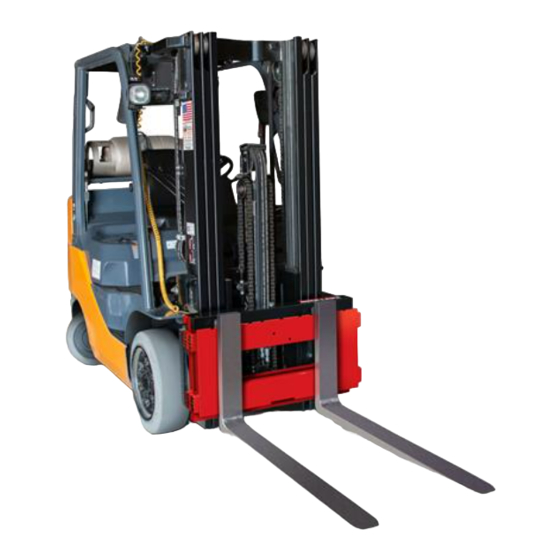
The CLS-420 is a rugged, dependable cargo lift scale that can withstand many years of repeated use. When mounted on a forklift, the CLS-420 saves time and money by allowing loads to be weighed immediately instead of carrying the load to a floor scale. -
Page 8: Safety
Do not operate or work on this equipment unless this manual has been read and all instructions are understood. Failure to follow the instructions or heed the warnings could result in injury or death. Contact any Rice Lake Weighing Systems dealer for replacement manuals. -
Page 9: Battery Disposal
When using Lithium-ion batteries, be sure to observe the following precautions for disposal as stated in the material safety data sheet regarding lithium-ion batteries. Figure 1-1. Material Safety Data Sheet - Lithium Ion Batteries © Rice Lake Weighing Systems ● All Rights Reserved... -
Page 10: Considerations Before Installation
Capacity Reduction Calculation While the CLS-420 will fit most typical forklifts, there are considerations that must be taken into account prior to installation. Due to the extra weight from the scale, the net lifting capacity of the forklift is reduced by approximately 10%. Use the formula below to calculate the amount to down-rate the lifting capacity and determine the net capacity of the forklift. -
Page 11: 420 Digital Indicator
If neither primary nor secondary units are lb or kg the lb is lit for primary units, the kg is lit for secondary units. • The following table shows which are used for all combinations of configured primary and secondary units. © Rice Lake Weighing Systems ● All Rights Reserved... -
Page 12: Modes Of Operation
CLS-420 Cargo Lift Scale Examples: a. If the primary unit is pounds (lb) and the secondary unit is kilograms (kg), the lb LED is lit for primary units, kg for secondary units. b. If the primary unit is pounds (lb) and the secondary unit is short tons (tn), the lb LED is lit for primary units, kg for secondary units. -
Page 13: Indicator Operations
Use the instructions for the style that was ordered. • Wired – coil cable, see Section 2.6 on page Figure 1-3. Wired Signal Coil Cable © Rice Lake Weighing Systems ● All Rights Reserved... -
Page 14: Iqube2 Junction Box
Junction Box The latest CLS-420 includes an updated version of the iQube junction box. This design is built to allow service technicians to easily service the unit in the field. It also replaces the older style j-boxes originally used. -
Page 15: Installation
The scale is shipped from the factory already calibrated to the indicator. Minimal recalibration and adjustments may be necessary once the scale is installed onto the fork lift. Calibration steps are contained in Section 3.3 on page Unpacking The CLS-420 is shipped upright on a sealed pallet with one or two scales per pallet. Hardware component boxes Figure 2-1. -
Page 16: Unpacking One Scale Configuration
CLS-420 Cargo Lift Scale 2.1.1 Unpacking One Scale Configuration Follow these instructions to unpack one scale. Scale Hardware component box Protective wood covering Wood shipping pallet Front pallet support Exploded view of components Hardware component box plastic banding Front pallet... -
Page 17: Unpacking Two Scale Configuration
Step 6: Clip plastic bands from scale two. Step 7: Remove protective wood covering for second scale. Scale two is ready for installation. Figure 2-3. Shipping Pallets for Two Scales © Rice Lake Weighing Systems ● All Rights Reserved... -
Page 18: Before Installation
Most propane, gas, and diesel fueled forklifts provide 12 volts of power. Some diesel models also provide 24 volts and electric forklifts provide 36 to 48 volts of power. The CLS-420 has a 9-36 VDC and a 10-60 VDC power supply option. -
Page 19: Scale Base Installation
2-5), so the lip of the cleat is behind the scale carriage. 7. Torque the bottom cleat retaining bolts to 125 ft-lb. Failure to properly torque the bottom plate retaining bolts may result in bodily harm or damage to equipment. WARNING © Rice Lake Weighing Systems ● All Rights Reserved... - Page 20 CLS-420 Cargo Lift Scale 8. Using the included feeler gauge, adjust the shim bolts so there is a minimal clearance between the bottom cleats and the scale carriage of 0.020'' thickness. Failure to adjust shim bolts to proper clearance of 0.020 inches may result in binding, poor accuracy or IMPORTANT improper fit of attachment to forklift.
-
Page 21: Install Forks
Assembly PN 162340 Figure 2-7. Connecting The Coiled Cable 1. Loosen the bolt holding the cover to the scale assembly and remove cover. 2. Assemble loop clamp kit to the coiled interface cable. © Rice Lake Weighing Systems ● All Rights Reserved... -
Page 22: Mounting The Indicator
CLS-420 Cargo Lift Scale 3. Route the coiled cable through the clips on backside of carriage toward middle. For proper coiled cable routing, tighten the clips. Set the other end of the cable aside until the power/communication box is installed. See Section 2.8.2 on... -
Page 23: Indicator Dimensions
Mount Plate Isolation Bumper Bonded Washer Bolt Side Brackets Figure 2-10. Mount Kit (PN 131630) ® To permanently lock the indicator mounting bolts, Rice Lake Weighing Systems recommends using Loctite 262. Note © Rice Lake Weighing Systems ● All Rights Reserved... -
Page 24: Cable Connections
CLS-420 Cargo Lift Scale 1. Install side brackets to the mount plate, using isolation bumpers and hardware (Figure 2-10). 2. Attach the mount assembly to the forklift frame at the location for the indicator. Lock Washer Bolt Large Flat Washer Figure 2-11. -
Page 25: Power Indicator With The Forklift Battery
Section 2.9 on Note page 24. The wireless version does not come with a coiled cable. Run power cable along the chassis to the forklift scale battery Figure 2-13. Power Cable © Rice Lake Weighing Systems ● All Rights Reserved... -
Page 26: Power Cable Connection
CLS-420 Cargo Lift Scale 2.8.2 Power Cable Connection Do not connect the power cable into the indicator until battery connection is complete. CAUTION Do not connect coiled interface cable into indicator until power hook-up is complete. The indicator draws its power from the forklift battery. After the indicator is mounted, run the power cable along the shortest path that provides protection for the cable (away from moving or hot objects and pinch points), to the forklift battery. -
Page 27: Power Cable To Battery Connection
Figure 2-17. Connect Positive Wire to Battery Cable 5. Follow the same procedure to connect the negative (black) wire to the negative battery-cable clamp. 6. Connect the ground (blue) wire to a suitable location on the chassis. © Rice Lake Weighing Systems ● All Rights Reserved... -
Page 28: Route The Load Cell Coiled Interface Cable
CLS-420 Cargo Lift Scale 7. After the connections are made at the battery, connect the cable to the power/communication box. Supplied termination hardware includes three 1/4" eyelets for 1/4" bolts. Note Wire Color Signal Positive on battery Black Negative on battery... -
Page 29: Grounding
2. Strip another 1/2'' (15 mm) of the insulation to expose the braid where the cable passes through the clamp. Load Cell Cables Cut the shield wire just past the grounding clamp. Shield wire function is provided by contact between the cable shield and the grounding clamp. © Rice Lake Weighing Systems ● All Rights Reserved... -
Page 30: Wireless Battery Option
CLS-420 Cargo Lift Scale Wireless Battery Option Wireless technology eliminates the need for the coiled interface cable. The reinforced battery box is welded onto the cover plate. There is an On/Off switch to conserve the life of the battery and an LED to indicate when the battery is on. Battery life is approximately 24 hours of continuous use, with only 8 hours to fully charge. -
Page 31: Charging The Lithium-Ion Battery
Dimensions (Maximum) Depth 22.80 mm Length 214.0 mm Volumetric Energy Density 466 Wh/I Gravimetric Energy Density 167 Wh/kg Maximum Hours of Charge 24 hours Nominal Capacity 6600 mAh Table 2-5. Battery Specifications © Rice Lake Weighing Systems ● All Rights Reserved... -
Page 32: General Precautions - Lithium Ion Battery
CLS-420 Cargo Lift Scale 2.14 General Precautions - Lithium ion Battery Below are general precautions that should be taken when handling lithium-ion batteries. WARNING Handling • Do not short circuit • Do not immerse in water • Do not disassemble or deform battery •... -
Page 33: Calibration And Configuration
2. Press to increment/decrement the value of the digit. 3. When the desired value is displayed, press to select it and move back to the previous parameter. © Rice Lake Weighing Systems ● All Rights Reserved... -
Page 34: Rezero
CLS-420 Cargo Lift Scale Rezero On CLS-420 systems shipped and installed November 1, 2017 and later, the REZERO function has been added. It allows calibration weight lifting devices to be used during the initial CMZERO (zero calibration) step. Perform a REZERO once calibration is complete to ensure a calibrated zero has been stored. -
Page 35: Front Panel Calibration
Use a level to ensure that the forklift tines are level prior to calibration. Note The test weight used to calibrate the CLS-420 cannot be greater than 2500 lb. To calibrate the indicator using the front panel, do the following: 1. -
Page 36: Front Panel Configuration
CLS-420 Cargo Lift Scale Front Panel Configuration The 420 indicator can be configured using a series of menus accessed through the indicator front panel, when the indicator is in setup mode. Menu Menu Function CONFIG Configuration – set grads, zero tracking, zero range, motion band, overload, tare function, sample rate and digital filtering parameters FORMAT Format –... -
Page 37: Format Menu
Decimal Point – determines the location of the decimal point or dummy zeros in the secondary unit display 888888 888880 • Primary Default: 88888.8 8.8888 • Secondary Default: 88.8888 888.888 8888.88 8888.8 Table 3-4. Primary and Secondary Parameters © Rice Lake Weighing Systems ● All Rights Reserved... -
Page 38: Calibration Menu
Table 3-6 illustrates the different serial settings used for CLS-420 functionality and a basic 420 indicator. The SSCALE parameter on the serial menu must be set to 2LCELL for use with the CLS-420 Cargo Lift Scale. If it is Note set to OFF, then the 420 indicator will function with a standard 420 calibration menu. - Page 39 (10 = 1 second) ECHO OFF - EDP Echo – enables or disables echoing of the serial commands sent to the indicator ON - Printer Table 3-8. EDP Port and Printer Port Parameters © Rice Lake Weighing Systems ● All Rights Reserved...
-
Page 40: Accumulate Function
CLS-420 Cargo Lift Scale Program Menu Parameter Choices Description PWRUPM Power up mode Indicator goes into operation immediately after a brief power up display test DELAY Indicator performs a power up display test, then enters a 30-second warm up period; if no motion is detected during the warm up period, the indicator becomes operational when the warm up period ends;... - Page 41 Front panel access to setpoints; specify OFF if setpoints will not be tested; ON enables operator to turn setpoints on/ off, change value or change BANDVAL using front panel entry during weigh mode Table 3-10. Setpoint Menu Parameters © Rice Lake Weighing Systems ● All Rights Reserved...
-
Page 42: Edp Configuration
CLS-420 Cargo Lift Scale EDP Configuration 3.5.1 EDP Command Configuration The serial command set can be used to configure the 420 indicator using either a personal computer, terminal, or remote keyboard. Serial command configuration sends commands to the indicator serial port; serial commands can be sent using any external device capable of sending ASCII characters over a serial connection. -
Page 43: Continuous Output (Stream) Format
O = Over/under range decimal point, leading zero supression Overload = ^^^^^^^ Underrange = ] ] ] ] ] ] ] Display overflow = OVERFL Figure 3-5. Continuous Output Data Format © Rice Lake Weighing Systems ● All Rights Reserved... -
Page 44: Test Mode
Test mode is intended for factory use only. Note In addition to normal and setup modes, test mode provides a number of diagnostic functions for the CLS-420, including: • Display raw A/D count • Reset configuration parameters to default values •... -
Page 45: Serial Communications
(low, 0 VDC) with reference to 5 VDC supply. LEDs on the CPU board light when the digital outputs are active. Port Connector Label Digital Input DI 1 DI 2 Digital Output DO 1 DO 2 Table 3-16. J2 and J6 Pin Assignments © Rice Lake Weighing Systems ● All Rights Reserved... -
Page 46: Cls-420 Abf Version
CLS-420 Cargo Lift Scale 3.10 CLS-420 ABF Version Figure 3-7. ABF Version Indicator 3.10.1 Wi-Fi Connectors All cable connections are into the back of the indicator. See Figure 2-12 on page There is a single cord grip with a WLAN antenna mounted in it. Loosen the cord grip to adjust the antenna position if needed. -
Page 47: Installed Wlan Interface
Calibration and Configuration 3.10.2 Installed WLAN Interface For use with ABF CLS-420 and Mega 8 indicators only. • The board is mounted to the 420 CPU board in place of the Analog Output module • The WLAN Port 1 serial connection connects to the Printer port on the 420 CPU board •... -
Page 48: Power The Carriage Junction Box
CLS-420 Cargo Lift Scale 3.10.4 Power the Carriage Junction Box Shown attached to CPU board Figure 3-9. Ind Opt, WLAN 420-CLS The WLAN CLS-420 indicator option can be ordered as an assembly or individual parts. Part No. Description Part No. -
Page 49: Special Matchport Firmware
Angle displays when the angle is over 3° Over or Under displays to indicate an overload or under load Reset the indicator if any settings become corrupt to return to default settings. See Section 3.10.3 on page Note © Rice Lake Weighing Systems ● All Rights Reserved... -
Page 50: Ascii Character Chart
CLS-420 Cargo Lift Scale 3.11 ASCII Character Chart Use the decimal values for ASCII characters listed in Tables 3-19 3-20 when specifying print format strings on the 420 PFORMT menu. The actual character printed depends on the character mapping used by the output device. - Page 51 æ ± Æ ³ ô £ ö ó ò õ û ÷ ù ˘ ÿ ° Ö • Ü ¢ £ ¥ ² ƒ Table 3-20. ASCII Character Chart (Part 2) © Rice Lake Weighing Systems ● All Rights Reserved...
-
Page 52: Front Panel Display Characters
CLS-420 Cargo Lift Scale 3.12 Front Panel Display Characters The 7-segment LED character set used to display alphanumeric characters on the 420 front panel. < & > Figure 3-10. Display Characters www.RiceLake.com Visit our website... -
Page 53: Conversion Factors For Secondary Units
2000.00 pounds short tons 1016.05 kilograms 907.185 kilograms 1.12000 short tons 0.892857 long tons 1.01605 metric tons 0.907185 metric tons NOTE: Multipliers in italics are preconfigured Table 3-21. Conversion Factors © Rice Lake Weighing Systems ● All Rights Reserved... -
Page 54: Parts And Service
CLS-420 Cargo Lift Scale Parts and Service Daily Inspection Checklist Check scale carriage for loose, worn, bent or broken components Inspect fork tines for damage Check locking pins on fork tines Inspect coiled cable for pinched, rubbed, stretched or damaged areas ... -
Page 55: Cargo Lift Scale Assembly
92810 Screw, Cap 162340 Scale Cover Assembly 109981 Bottom Cleat, 34'' 97118 Scale Cover Assembly 111123 Screw, Cap 53308 Label,1.25 x 1.25 8000T Table 4-1. Cargo Lift Scale Assembly Parts List © Rice Lake Weighing Systems ● All Rights Reserved... -
Page 56: Load Cell Assembly
CLS-420 Cargo Lift Scale 4.2.1 Load Cell Assembly Figure 4-2. Load Cell Replacement Kit Parts Illustration Item No. Part No. Description 97883 Load Cell Replacement Kit (inc items 1, 2, 5, 4, 6 & 8) 109958 Hex Nut 15198 Spherical Washer Set... -
Page 57: Iqube2 Junction Box Assembly (Pn 167261), 28'' And 34'' Models
CR-FHMS 0.164-32 x 0.5 x 0.5-N-SST 163765 Gasket, Access Cover 162384 Cover Plate, Access Hole 75062 Sealing Washer, #8 30623 Screw, 8-32NC x 7/16 52342 Label Table 4-3. iQube Junction Box Assembly (PN 167261) © Rice Lake Weighing Systems ● All Rights Reserved... -
Page 58: Junction Box With Quick Disconnects (Pn 130826)
CLS-420 Cargo Lift Scale 4.2.3 Junction Box with Quick Disconnects (PN 130826) 10 1 This cable assembly connect to J4 This cable assembly connect to J5 Figure 4-4. Junction Box with Quick Disconnects (PN 130826) Item No Part No Description... -
Page 59: Protective Angle With Battery Box Assembly
Parts and Service 4.2.4 Protective Angle with Battery Box Assembly Part of item 9 Figure 4-5. Protective Angle with Battery Box Parts Illustration © Rice Lake Weighing Systems ● All Rights Reserved... - Page 60 CLS-420 Cargo Lift Scale Item Part No. Description 126538 Cover, 14GA W/Dual 112729 Draw Latch, Over Center 129551 Weldment, Protective Angle 38'' 126535 Weldment, Protective Angle 34'' 152481 Weldment, Protective Angle 28'' 14618 Nut, Kep 4-40NC HEX 14862 Screw, Mach 8-32NC x3 /8...
-
Page 61: Cls-420 Indicator (Pn 162310) 5 Pin Wired With Power Switch
Parts and Service CLS-420 Indicator (PN 162310) 5 Pin Wired with Power Switch Figure 4-6. CLS-420 Indicator Parts Illustration (PN 163866 and 168259) © Rice Lake Weighing Systems ● All Rights Reserved... - Page 62 Nameplate, Rice Lake 84389 Bracket, Power Supply 420 Indicator 84397 Overlay, 420 Indicator Membrane Switch-Panel 99151 Board Assembly, CPU Display CLS-420 With Software 174435 Gasket, 420 Cover Plate 45043 Wire, Ground 4'' w/ No.8 Eyelet Connector 45042 Bonded Sealing Washer, #8...
-
Page 63: Cls 420 Indicator, 10 Pin Connector, Used With Iqube (98413)
Connection Option From Power Supply Cable Assembly Zigbee Wireless Option Ground Wire to Back Plate To Power Supply Ground Wire From Power Assembly Section A-A Figure 4-7. CLS-420 Indicator Parts Illustration © Rice Lake Weighing Systems ● All Rights Reserved... - Page 64 Cable Assembly, DC Power 57241 Gasket, MS Conn Shell Size 67755 Spacer, Brass I.D. #8 80331 Connector, Tap and Run 71125 Conn, 3 Pos Screw Terminal 110388 Tape, Kapton 1'' 2 mil Table 4-7. CLS-420 Indicator Parts List www.RiceLake.com Visit our website...
-
Page 65: Mount Assembly For Cls-420 Indicator (Pn 162310)
Screw, Cap 1/4-20NC x 1-3/4 44676 Washer, Bonded Sealing 121003 Mounting Plate, 420-CLS 98537 Bumper, Recessed Rubber 121004 Bracket, Side Angled 14634 Nut, Lock 1/4-20NC HEX Table 4-8. Mount Assembly Parts List © Rice Lake Weighing Systems ● All Rights Reserved... -
Page 66: Mount Assembly For Cls-420 Indicator
CLS-420 Cargo Lift Scale 4.3.3 Mount Assembly for CLS-420 Indicator Figure 4-9. Mount Assembly Parts Illustration (PN 98413) Item No. Part No. Description 14656 Nut, 3/8-16NC Hex 15159 Washer, Lock, 3/8 Regular 96929 Clamp Plate, Indicator 14984 Screw, Cap 1/4-20NC x 1-3/4... -
Page 67: Cls-420 Indicator Cpu Board Replacement
2. Remove the screws that hold the backplate to the enclosure body, then lift the backplate away from the enclosure and set aside. 3. Disconnect the power supply cable from connector J7 on the 420 CPU board. © Rice Lake Weighing Systems ● All Rights Reserved... -
Page 68: Nema 4X Polycarbonate Junction Box Maintenance
NEMA 4X Polycarbonate Junction Box Maintenance The CLS-420 scale can use a NEMA Type 4X polycarbonate junction box. The junction box is located between the front and back panel of the scale and is covered by a metal cover plate on the top of the scale. Use the following procedures for replacing a junction box on the CLS-420. -
Page 69: Junction Box Board Replacement - Two Board Style (Prior To December 2010)
3. Flip the top board up and back out of the way. The wires connecting the top and bottom boards are long enough to accommodate this. 4. Disconnect the wiring from the bottom board. 5. Loosen the screws and standoffs to remove bottom board and replace with new board. © Rice Lake Weighing Systems ● All Rights Reserved... - Page 70 CLS-420 Cargo Lift Scale 6. Tighten the screws and standoff to secure the new board. The bottom board which is shown in Figure 4-16 connects the wiring for both load cells one and two. Table 4-10 lists Note the wiring assignments for the bottom board.
- Page 71 TEMP (green) NEG (black) Table 4-11. Top Board Wiring Connections J6 wiring is only used in the wireless version of the CLS series and goes directly to the battery box. Note © Rice Lake Weighing Systems ● All Rights Reserved...
-
Page 72: Junction Box Board Replacement And Wiring - One Board Style (December 2010 And Later)
CLS-420 Cargo Lift Scale 4.5.2 Junction Box Board Replacement and Wiring – One Board Style (December 2010 and Later) To access the board: 1. Using a Phillips head screwdriver, loosen screws and remove the junction box cover. 2. Disconnect the wiring from the board. - Page 73 Quick Connect Cable Assembly Position on J4 and Wire Color Position on J2 Wire Color Green Black White Green Blue Black White Empty Brown Orange Empty +3.3V Table 4-12. Wiring Connections © Rice Lake Weighing Systems ● All Rights Reserved...
-
Page 74: Iqube2 Junction Box Maintenance/Upgrade
The iQube junction box is designed for use with the Rice Lake CLS-420 forklift scales and is a replacement for the junction box used on early models of the scale. The load cell connectors have been updated to improve serviceability. -
Page 75: Iqube2 Pcb Board Assembly Replacement
2. Disconnect load cell and coiled cable connectors. 3. Loosen four screws to remove front cover of j-box. 4. Disconnect JST connectors for load cells and coiled cable. 5. Remove PCB board assembly. © Rice Lake Weighing Systems ● All Rights Reserved... -
Page 76: Iqube 2.3 Cross References
When identifying the correct junction box cross referenced part number, please provide the serial number of the scale so the Rice Lake Weighing Systems sales and service departments can track it to the correct top level part number sold. To verify the correct junction box has been received, use Table 4-13, the iQube 2.3 junction box part number reference table. -
Page 77: Load Cell Maintenance
Table 4-13. iQube 2.3 Cross References Load Cell Maintenance This section describes procedures for replacing a load cell. The CLS-420 uses Rice Lake’s load cell, PN 125543. The following instructions must be followed exactly to allow for seamless and easy load cell replacement. -
Page 78: Load Cell Replacement
CLS-420 Cargo Lift Scale 4.7.2 Load Cell Replacement #1 Upper hex nut #2 Upper hex nut #3 Spherical washer set #4 Upper block #5 Spherical washer set #6 Hex nut #7 Jam nut #8 Flexure rod #9 Jam nut Modified... - Page 79 5. Loosen jam nut (#7) from the upper block using the special modified box wrench (PN 96196 - supplied with load cell replacement kit) and shown in Figure 4-25. 6. Loosen jam nut (#13) from the lower block. 7. Remove the top hex nut (#2) and the top spherical washer set (#3). © Rice Lake Weighing Systems ● All Rights Reserved...
- Page 80 CLS-420 Cargo Lift Scale Figure 4-28. Remove Bottom Nut It is acceptable if the load cell slightly rotates up against the front or back plate of the scale. Note 8. Remove the bottom hex nuts (#18 and #19) and the bottom spherical washer set (#17).
- Page 81 Figure 4-32. Load Cell 20. Install the top and bottom flexure rod with hardware, ensuring that the flexure rod is oriented with the short thread of the rod facing nearest the load cell. © Rice Lake Weighing Systems ● All Rights Reserved...
- Page 82 CLS-420 Cargo Lift Scale Short threads facing nearest the load cell. Figure 4-33. Installing Flexure 21. Insert the load cell and thread flexure rods into top and bottom of the load cell making sure the appropriate hex nuts, jam nuts, and spherical washers are in the correct order per Figure 4-25 on page 22.
- Page 83 27. Use a pry bar or chisel to hold the bottom half of the load cell straight while using a torque wrench to tighten the bottom hex nut on the lower mounting block to 110 ft-lb. Install the other hex nut on the bottom of the flexure rod and torque it to 110 ft-lb. © Rice Lake Weighing Systems ● All Rights Reserved...
- Page 84 CLS-420 Cargo Lift Scale Figure 4-37. Center Load Cell Figure 4-38. Tighten Lower Nut 28. Use the special modified box wrench to tighten the jam nut (#13) on the lower block. 29. Remove the flat-bladed screwdriver used in Step 25 and inspect the flexure rod. The flexure rod must be in the center of the hole.
-
Page 85: Forklift Flexure Troubleshooting - 28" And 34" Models
3. Check the dimensions of the flexure for damage. There should be a +/-0.03" tolerance to the drawing shown below for height and width. 4X 0.25 3.00" 4.12" Figure 4-39. Flexure Chassis © Rice Lake Weighing Systems ● All Rights Reserved... -
Page 86: Cls-420 Wiring Diagrams
CLS-420 Cargo Lift Scale 4.7.4 CLS-420 Wiring Diagrams Figure 4-40. CLS-420 Indicator Wiring Diagram www.RiceLake.com Visit our website... -
Page 87: Led Functions
On when lit (active low) DO 2 (Digital Out 2) On when lit (active low) DI 1 (Digital In 1) On when lit (active low) DI 2 (Digital In 2) On when lit (active low) © Rice Lake Weighing Systems ● All Rights Reserved... -
Page 88: Troubleshooting
CLS-420 Cargo Lift Scale Troubleshooting Troubleshooting Chart Symptom Possible Cause Action Scale reading high against test weight Debris between the scale and the forklift carriage Remove debris Debris between the front and back scale plates Remove debris Centering pin touching the forklift carriage, causing it to... - Page 89 May have to grind or torch side of forklift carriage due to previously installed side shift protection method Scale displaying negative weight Forks are resting (even slightly) on the floor Lift forks up off floor Table 5-1. Troubleshooting © Rice Lake Weighing Systems ● All Rights Reserved...
-
Page 90: Error Messages
CLS-420 Cargo Lift Scale Error Messages The CLS-420 provides a number of front panel error messages to assist in problem diagnosis. Displayed Error Messages Table 5-2 lists these messages and their meanings. Error Message Description Solution E A/D A/D physical error... -
Page 91: Cls-420 Specifications
• This device must accept any interference received, including interference that may cause undesired operation. Certifications and Approvals CoC Number 06-074 (5,000 lb only) per H-44 at 1,000 divisions Accuracy Class III/III L : 10 000 © Rice Lake Weighing Systems ● All Rights Reserved... - Page 92 CLS-420 Cargo Lift Scale www.RiceLake.com Visit our website...
- Page 94 Specifications subject to change without notice. Rice Lake Weighing Systems is an ISO 9001 registered company. 230 W. Coleman St. • Rice Lake, WI 54868 • USA U.S. 800-472-6703 • Canada/Mexico 800-321-6703 • International 715-234-9171 • Europe +31 (0)26 472 1319...
Need help?
Do you have a question about the CLS-420 and is the answer not in the manual?
Questions and answers