Table of Contents
Advertisement
Quick Links
Download this manual
See also:
User Manual
Advertisement
Table of Contents

Summary of Contents for Patton electronics 1088/K
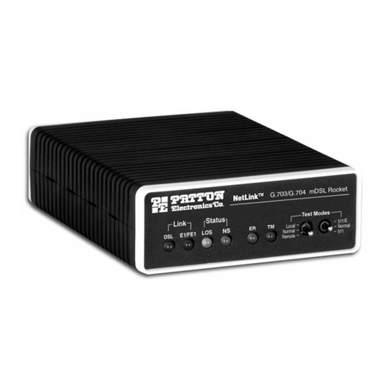
- Page 1 USER MANUAL MODEL 1088/K mDSL Modem with fixed G.703/G.704 Interface Part# 07M1088/K-C SALES OFFICE Doc# 033141UC (301)975-1000 Revised 06/08/00 TECHNICAL SUPPORT (301)975-1007 An ISO-9001 http://www.patton.com Certified Company...
-
Page 2: Radio And Tv Interference
If this product fails or does not perform as warranted, your sole 1.3 Service recourse shall be repair or replacement as described above. Under no condition shall Patton Electronics be liable for any damages incurred 2.0 General Information...............4 by the use of this product. These damages include, but are not limited 2.1 Features... - Page 3 Carrierless Amplitude and Phase (CAP) modulation. Equipped with both 75 ohm (dual coax) and 120 ohm (RJ-45), the Model 1088/K is easy to configure and install. DSL line connection is via RJ-45 jack.
-
Page 4: Configuring The Hardware Dip Switches
Figure 1. Underside of Model 1088/K, Showing Location of DIP Switches The Model 1088/K does not use clock mode settings as described The two sets of DIP switches on the underside of the Model 1088/K in other Patton mDSL products. Instead, the Model 1088/K will always recover the clocking from the G.703/4 network and use this... - Page 5 CO/CP designation. This is already done inter- tion. When CRC-4 is enabled (ON), the unit synchronizes to the CRC- nally within the unit. When connecting a 1088/K to an mDSL modem 4 multi-frame protocol. (e.g. Model 1088/C, 1088/D or 1095) other then a Model 1088/K,...
- Page 6 S2-1 DTE Rate S2-2 DTE Rate NOTE: Based on the DTE rate chosen, the Model 1088/K will S2-3 DTE Rate automatically select the optimum line rate for the distance. This 2048 kbps selection is based on the lowest line rate that will support the...
-
Page 7: Netlink Plug-And-Play
The NetLink Plug and Play application will also work in an 3.2 NETLINK PLUG-AND-PLAY HTTP/SNMP managed system using the NetLink Model 1001MC SNMP agent card with 1095RC cards installed in PattonÕs 2U rack sys- The NetLink Plug-and-Play feature allows ISPs, carriers and PTTs tem. -
Page 8: Jumper Configuration
The Power, G.703/G.704 and DSL Line connections are located 4.2.1 Connect Twisted Pair (120 ohm) to G.703 Network on the rear panel of the Model 1088/K. Figure 4, below, shows the location of each of these ports. The Model 1088/K is equipped with a single RJ-48C jack for con- nections to a 120 ohm twisted pair G.703/G.704 network interface. - Page 9 Model 1088 plugs in a DC source (nominal 48VDC) and plugs into polarity insensitive and is wired for a two-wire interface. The signal/pin the barrel power supply jack on the rear of the 1088/K. Please refer to relationships are shown in Figure 8.
-
Page 10: Led Status Monitors
Model 1088. Fuse replacement source. should only be performed by qualified service personnel. Contact Patton Electronics Technical support at (301)975- 5.2 LED STATUS MONITORS 1007, via our web site at http://www.patton.com, or by e-mail The Model 1088 features six front panel LEDs that monitor power, at support@patton.com, for more information. -
Page 11: Test Modes
(Active Yellow) glows yellow to indicate that the it will restart the box and begin trying to re- Model 1088/K has been placed in Test Mode. The establish a connection with the far end. The dis- unit can be placed in test mode by the local user tinction between framed packets and unframed or by the remote user. - Page 12 5.3.2 Loops and Patterns Restart Procedure The restart procedure is in place to allow the and Time Outs units to re-establish a connection after the The following section describes the Test Modes used in the Model framer begins seeing unframed packets. The 1088.
- Page 13 Local Loop After the 511/511E pattern times out, the ER led Pattern Framer Loop Loop Pattern Framer with 511/511E will begin flashing. It will remain this way until Line Contr Contro Gen/Det Gen/Det (continued) the pattern generator switch is turned off. Note that the data at the local DTE and the remote DTE are not valid.
- Page 14 Remote Digital The Remote Loop uses the EOC channel (an Remote Digital The Remote Digital Loop with 511/511E is Loop out-of-band signaling channel) to establish the Loop with shown above. After RDL is established the remote link. Upon the RDL switch being thrown 511/511E Remote units' Restart Timer is set to one or DTE initiation, a RDL_ON Request signal is...
- Page 15 Data Mode with When the units enter DataMode it is possible to 5.3.3 Using the V.52 (BER) Test Pattern Generator 511/511E Pattern turn on the 511/511E pattern generators on Generators both ends of the link. Once a 511/511E pattern To use the V.52 BER tests in conjunction with the Remote Digital is selected on one end of the link, the pattern Loopback tests (or with Local Line Loopback tests), follow these generator will begin transmitting unframed...
- Page 16 A A P P P P E E N N D D I I X X A A A A P P P P E E N N D D I I X X B B PATTON ELECTRONICS G.703 SDSL MODEM PATTON ELECTRONICS MODEL 1088/K...
- Page 17 A A P P P P E E N N D D I I X X C C Transmission Distance Chart Distance Table Model 1095/1088 mDSL Modem Standalone and Rack card NO NOISE Line Rate DTE Rates 26g (0.4mm) 24g (0.5mm) 22g (0.6mm) 20g (0.8mm) 19g (0.9mm)


Need help?
Do you have a question about the 1088/K and is the answer not in the manual?
Questions and answers