
Subscribe to Our Youtube Channel
Related Manuals for Trane 7½ - 20 Tons


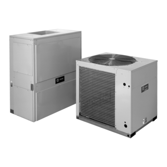
Summary of Contents for Trane 7½ - 20 Tons
- Page 1 Split System Heat Pumps Split System Heat Pumps 7½ - 20 Tons - 60 Hz Air Handlers 5-20 Tons - 60 Hz SSP-PRC001-EN February 2008...
-
Page 2: Introduction
In addition, all cabinets have been standardized. When you are Your Needs In Mind. servicing an outdoor unit or an air The Trane reputation for quality and handler, all components are in the reliability in air conditioning is same location from unit to unit. -
Page 3: Table Of Contents
Contents Introduction ............Features and Benefits . -
Page 4: Features And Benefits
You’ll find Odyssey will win you even more jobs with its compact, manageable cabinet which will save time and money for rigging and installation and permit Trane to replace almost any unit — effortlessly. Each heat pump unit can operate to 50°F as standard in the cooling... - Page 5 Unlike some competitive models the following components are factory- installed in Trane air handlers: • Single Point Power Entry • Blower Wheel and Housing •...
-
Page 6: Application Considerations
Actual clearances which appear inadequate should be reviewed with a local Trane Representative. 180° Blower Rotation The 5, 7½ and 10 ton air handler blower section can be rotated 180° to change the discharge pattern. - Page 7 Application Considerations Figure 7. Typical Vertical Air Handler Application SSP-PRC001-EN...
-
Page 8: Selection Procedure
0.12 in. d. Airflow: 3000 cfm Calculate the building heating load of water (0.77 + 0.12 = .89 in.) External Static Pressure: using the Trane calculation form or 0.77 inches of water gauge Enter Table 17 for TWE090A4 at 3000 any other standard accepted cfm and .90 static pressure. -
Page 9: Model Number Description
Model Number Description Split System Heat Pump Model Nomenclature Digits 1,2,3 - Product Type Digits 8 - Electrical Characteristics Digits 11 - Minor Design Sequence TWA = Split System Heat Pump 1 = 208-230/60/1 A = Current Design Sequence 3 = 208-230/60/3 Digits 4,5,6 - Nominal Gross Cooling Digits 12 - Service Digit Capacity (MBh) -
Page 10: General Data
10.82/3.2 16.10/3.1 22.42/3.1 Low Temperature Capacity 55,000 80,000 106,000 154,000 System kW/COP 6.73/2.4 9.62/2.4 14.16/2.2 19.54/2.30 Compressor No./Type 1/Trane 3-D Scroll 1/Trane 3-D Scroll 2/Trane 3-D Scroll 2/Trane 3-D Scroll No. Motors/HP 1/7.5 1/10 2/7.5 2/10 Motor RPM 3450 3450... - Page 11 General Data Table 2. General Data - Air Handlers 5 Tons 7½ Tons 10 Tons Single Circuit Dual Circuit Single Circuit Dual Circuit Single Circuit (ii) TWE060A1 TWE060B1, B3, TWE090A1, TWE090B1, Single Circuit TWE120A3 (ii) (ii) (iii) A3, A4, AW , AW TWE120A1 System Data...
-
Page 12: Performance Data
Performance Data Table 3. Gross Cooling Capacities (MBh) 7½ Tons TWA090A Heat Pump with 7½ TWE090A Air Handler Ambient Temperature Entering WB CFM Air flow DB °F 2700 84.1 67.2 92.8 56.3 102.1 37.7 81.2 65.7 89.5 55.0 98.5 36.4 78.0 64.2 86.1... - Page 13 Performance Data 10 Tons Gross Cooling Capacities Table 4. Gross Cooling Capacities (MBh) 10 Ton TWA120A Heat Pump with 10 Ton TWE120A Air Handler Ambient Temperature Entering WB CFM Air flow DB °F 3600 114.6 90.1 126.2 76.3 138.8 51.1 110.6 88.1 121.8 74.5 134.0 49.4 106.2 85.9 117.1 72.6 128.9 47.7 115.0 104.8 126.4 85.8 138.8 66.4 111.1 102.8 122.0 83.9 134.0 64.6 106.9 100.7 117.3 81.9 128.9 62.6 117.1 117.1 126.5 100.7 138.8 81.2 113.7 113.7 122.0 98.6 134.0 79.3 110.1 110.1 117.4 96.5 129.0 77.4 122.7 122.7 126.9 115.2 138.9 95.9 119.2 119.2 122.7 113.2 134.2 94.0 115.5 115.5 118.2 111.1 129.1 92.1...
- Page 14 Performance Data 15 Tons Gross Cooling Capacities Table 5. Gross Cooling Capacities (MBh) 15 Tons TWA180B Heat Pump with 15 Tons TWE180B Air Handler Ambient Temperature Entering WB CFM Air flow DB °F SHC MBH MBH SHC MBH MBH SHC 5400 167.8 134.1 185.1 112.3 203.6 75.2 161.9 131.2 178.6 109.7 196.4 72.7 155.5 171.6 106.9 188.9 70.1...
- Page 15 Performance Data 20 Tons Gross Cooling Capacities Table 6. Gross Cooling Capacities (MBh) 20 Tons TWA240B Heat Pump with 20 Ton TWE240B Air Handler Ambient Temperature Entering WB CFM Air flow DB °F SHC MBH MBH SHC MBH MBH SHC 7200 223.8 177.3 148.8 269.9 99.5 215.5 173.1...
-
Page 16: Table Of Contents
Performance Data 7½ Tons Gross Cooling Capacities and Capacity Curves Table 7. Gross Cooling Capacities (MBh) 7½ Tons TWA090A Heat Pump Only Suction Temperature (°F) Outdoor Temp (°F) Head press PSIG Cap. Btuh/1000 97.2 105.8 114.5 123.4 Unit kW 5.56 5.69 5.83 5.97... - Page 17 Performance Data 10 Tons Gross Cooling Capacities and Capacity Curves Table 8. Gross Cooling Capacities (MBh) 10 Tons TWA120A Heat Pump Only Suction Temperature (°F) Outdoor Temp (°F) Head press PSIG Cap. Btuh/1000 110.6 121.1 132.1 143.7 155.9 168.6 Unit kW 7.87 8.04 8.22...
- Page 18 Performance Data 15 Tons Gross Cooling Capacities and Capacity Curves Table 9. Gross Cooling Capacities (MBh) 15 Tons TWA180B Heat Pump Only Suction Temperature (°F) Outdoor Temp (°F) Head press PSIG Cap. Btuh/1000 161.3 177.1 193.6 210.6 228.1 245.8 Unit kW 10.9 11.16 11.43...
- Page 19 Performance Data 20 Tons Gross Cooling Capacities and Capacity Curves Table 10. Gross Cooling Capacities (MBh) 20 Tons TWA240B Heat Pump Only Suction Temperature (°F) Outdoor Temp (°F) Head press PSIG Cap. Btuh/1000 217.4 237.4 258.4 280.5 303.5 327.5 Unit kW 16.09 16.51 16.96...
- Page 20 Performance Data 7½, 10 Tons Gross Heating Capacities Table 11. Gross Heating Capacities (MBh) 7½ Tons TWA090A Heat Pump with 7½ Tons TWE090A Air Handler at 3000 CFM Heating Capacity (BTUH/1000) Total Power in kW at Indicated Indoor Dry Bulb Temperature at Indicated Indoor Dry Bulb Temperature Outdoor Temp (°F)
- Page 21 Performance Data 15, 20 Tons Gross Heating Capacities Table 13. Gross Heating Capacities (MBh) 15 Tons TWA180B Heat Pump with 15 Tons TWE180B Air Handler at 6000 CFM Heating Capacity (BTUH/1000) Total Power in kW at Indicated Indoor Dry Bulb Temperature at Indicated Indoor Dry Bulb Temperature Outdoor Temp (°F)
- Page 22 2. Fan motor heat (MBh) = 3.15 x BHP. 3. Trane’s factory supplied motors, in commercial equipment, are definite purpose motors, specifically designed and tested to operate reliably and continuously at all cataloged conditions. Using the full horsepower range of our fan motors as shown in our tabular data will not result in nuisance tripping or premature motor failure.
- Page 23 2. Fan motor heat (MBh) = 3.15 x BHP. 3. Trane’s factory supplied motors, in commercial equipment, are definite purpose motors, specifically designed and tested to operate reliably and continuously at all cataloged conditions. Using the full horsepower range of our fan motors as shown in our tabular data will not result in nuisance tripping or premature motor failure.
- Page 24 2. Fan motor heat (MBh) = 3.15 x BHP. 3. Trane’s factory supplied motors, in commercial equipment, are definite purpose motors, specifically designed and tested to operate reliably and continuously at all cataloged conditions. Using the full horsepower range of our fan motors as shown in our tabular data will not result in nuisance tripping or premature motor failure.
- Page 25 2. Fan motor heat (MBh) = 3.15 x BHP. 3. Trane’s factory supplied motors, in commercial equipment, are definite purpose motors, specifically designed and tested to operate reliably and continuously at all cataloged conditions. Using the full horsepower range of our fan motors as shown in our tabular data will not result in nuisance tripping or premature motor failure.
- Page 26 2. Fan motor heat (MBh) = 3.15 x BHP. 3. Trane’s factory supplied motors, in commercial equipment, are definite purpose motors, specifically designed and tested to operate reliably and continuously at all cataloged conditions. Using the full horsepower range of our fan motors as shown in our tabular data will not result in nuisance tripping or premature motor failure.
- Page 27 2. Fan motor heat (MBh) = 3.15 x BHP. 3. Trane’s factory supplied motors, in commercial equipment, are definite purpose motors, specifically designed and tested to operate reliably and continuously at all cataloged conditions. Using the full horsepower range of our fan motors as shown in our tabular data will not result in nuisance tripping or premature motor failure.
- Page 28 Performance Data 5-20 Tons Motor and Fan Speed, Electric Heat Discharge Plenum and Grille Airflow Table 27. Standard Motor and Sheave/Fan Speed (RPM) - Air Handler Sheave Position 6 Turns 5 Turns 4 Turns 3 Turns 2 Turns 1 Turns Tons Unit Model No.
- Page 29 Performance Data Discharge Plenum and Grille Assembly Throw Distance Table 30. Discharge Plenum and Grille Assembly Throw Distance (ft) — Air Handler Louver Angle Deflection Position Tons Model No. Straight 20° 40° 55° 1600 TWE060A 1800 TWE060B 2000 2200 2400 2400 TWE090A 2700...
- Page 30 Performance Data 5-20 Tons Static Pressure Drop, Auxiliary Heat Capacity Table 31. Static Pressure Drop Through Accessories (inches of water column) - Air Handlers Discharge Electric Heaters (kW) Hydronic Coils Return Plenum and (ii) Tons Unit Model No. Grille Grille 5-10 15-20 25-30...
-
Page 31: Controls
Controls Thermostats Touchscreen Programmable Digital Display Thermostat Thermostat (2H/2C) (3H/2C) Two stage heating/cooling or one stage heating/cooling thermostats Two Heat/Two Cool programmable Three Heat/Two Cool digital display are available in either manual or thermostat with touch screen digital thermostat. Easy access battery automatic changeover. -
Page 32: Electrical Data
Electrical Data Table 33. Unit Wiring - Heat Pumps Maximum Fuse Size or Unit Operating Voltage Minimum Circuit Maximum Circuit Tons Unit Model No. Range Ampacity Breaker TWA090A3 187-253 34.5 7½ TWA090A4 414-506 18.1 TWA090AW 518-632 14.5 TWA120A3 187-253 48.1 TWA120A4 414-506 23.3... - Page 33 Electrical Data 5-20 Tons, Air Handler Unit Wiring, Electrical Characteristics Table 35. Unit Wiring - Air Handler Maximum Fuse Unit Operating Minimum Circuit or HACR Circuit Tons Unit Model Number Voltage Range Ampacity Breaker Size TWE060A1,B1 187-253 TWE060A3,B3 187-253 TWE060A4,B4 414-506 TWE060AW 518-632...
- Page 34 Electrical Data Unit Wiring with Electric Heat Table 37. Unit Wiring with Electric Heat (Single Point Connection) - 5, 7½ and 10 Ton Air Handlers Maximum Fuse Maximum Fuse or Heater KW Unit Power Minimum Circuit HACR Circuit (ii) (ii) (iii) Heater Model No.
- Page 35 Electrical Data Unit Wiring with Electric Heat Table 37. Unit Wiring with Electric Heat (Single Point Connection) - 5, 7½ and 10 Ton Air Handlers Maximum Fuse Maximum Fuse or Heater KW Unit Power Minimum Circuit HACR Circuit (ii) (ii) (iii) Heater Model No.
-
Page 36: Jobsite Connections
Jobsite Connections Wiring shown with dashed lines is to Figure 16. Title goes here in this table cell be furnished and installed by the customer. All customer- supplied wiring must be copper only and must conform to NEC and local electrical codes. -
Page 37: Typical Wiring
Typical Wiring Figure 17. Heat Pump - Single Compressor. For specific wiring, see individual Service Facts. SSP-PRC001-EN... - Page 38 Typical Wiring Heat Pump Single Compressor Wiring Diagram Figure 17. (continued from previous page)Heat Pump - Single Compressor. For specific wiring, see individual Service Facts. SSP-PRC001-EN...
- Page 39 Typical Wiring Heat Pump Dual Compressor Wiring Diagram Figure 18. Heat Pump - Dual Compressor. For specific wiring, see individual Service Facts. SSP-PRC001-EN...
- Page 40 Typical Wiring Heat Pump Dual Compressor Wiring Diagram Figure 18. (continued from previous page)Heat Pump - Dual Compressor. For specific wiring, see individual Service Facts. SSP-PRC001-EN...
- Page 41 Typical Wiring Air Handler Wiring Diagram Figure 19. Air Handler. For specific wiring, see individual Service Facts. SSP-PRC001-EN...
-
Page 42: Dimensional Data
Dimensional Data Figure 20. 7½ Tons TWA090 Heat Pump. All dimensions are in inches. SSP-PRC001-EN... - Page 43 Dimensional Data 10 Tons Figure 21. 10 Tons TWA120A Heat Pump. All dimensions are in inches. SSP-PRC001-EN...
- Page 44 Dimensional Data 15 Tons Figure 22. 15 Tons TWA180B Heat Pump. All dimensions are in inches. SSP-PRC001-EN...
- Page 45 Dimensional Data 20 Tons Figure 23. 20 Tons TWA240B Heat Pump. All dimensions are in inches. SSP-PRC001-EN...
- Page 46 Dimensional Data 5 Tons Figure 24. 5 Tons TWE060A, 060B Air Handlers. All dimensions are in inches. Table 39. Air Handler Dimensions (in.) Tons Model No. TWE060A 19-1/2 15-7/8 14-1/8 1-7/8 42-1/8 34-5/8 TWE060B 19-1/2 16-1/4 13-1/4 1-1/8 42-1/8 34-5/8 Tons Model No.
- Page 47 Dimensional Data 7½ & 10 Ton Figure 25. 7½ & 10 Tons TWE090A, 120A; TWE090B, 120B Air Handlers. All dimensions are in inches. Table 40. Air Handler Dimensions (in.) Tons Model No. 7½ TWE090A 47-1/2 11-3/4 22-3/8 — 17-3/4 45-1/4 7½...
- Page 48 Dimensional Data 5 - 10 Ton Figure 26. 5-10 Tons TWE060A, 090A, 120A; TWE060B, 090B, 120B Air Handlers Table 41. Air Handler Dimensions (in.) Tons Model No. TWE060A,060B 34-5/8 2 7/8 35-5/8 12 1/4 32-1/4 12 1/2 7 5/8 7½ TWE090A, 090B 36-7/8 6 5/8...
- Page 49 Dimensional Data 15 Tons Figure 27. 15 Tons TWE180 Air Handlers. All dimensions are in inches. SSP-PRC001-EN...
- Page 50 Dimensional Data 15 Tons Figure 28. 15 Tons TWE180 Air Handlers Figure 29. 15 Tons TWE180 Air Handlers Table 42. Air Handler Dimensions (in.) Tons Model No. TWE180B 79-1/2 27-5/8 12-3/8 1-5/8 25-1/8 49-1/8 56-1/4 15-1/2 19-1/2 77-1/4 1 1/4 Tons Model No.
- Page 51 Dimensional Data 20 Tons Figure 30. 20 Tons TWE240B Air Handlers SSP-PRC001-EN...
- Page 52 Dimensional Data 20 Tons Figure 31. 20 Ton TWE240B Air Handlers Figure 32. 15 Tons TWE180 Air Handlers Table 43. Air Handler Dimensions (in.) Tons Model No. TWE240B 71-7/8 92-1/2 30-1/2 18-7/8 4-1/2 51-7/8 59-1/8 18-1/8 20-7/8 89-1/4 1 3/4 50-7/8 Tons Model No.
- Page 53 Dimensional Data Accessories, Electric Heater Figure 33. Electric Heater for 5, 7½ and 10 Ton Air Handlers. All dimensions are in inches. Figure 34. Electric Heater for 15 and 20 Ton Air Handlers. All dimensions are in inches. SSP-PRC001-EN...
- Page 54 Dimensional Data Accessories, Discharge Plenum and Grille Table 44. Discharge Plenum and Grille Tons Model No. BAYPLNM015 37-15/16 21-15/16 7½ BAYPLNM016 47-1/2 BAYPLNM017 63-1/2 Table 45. Discharge Plenum and Grille Dimensions (in.). For use with Electric Heat Tons Model No. BAYPLNM025 37-15/16 21-15/16...
- Page 55 Dimensional Data Accessories, Subbase Table 47. Subbase Dimensions (in.) Tons Model No. BAYBASE001 7½ BAYBASE002 47-1/2 BAYBASE003 63-1/2 BAYBASE004 79-1/2 27-5/8 BAYBASE005 92-1/2 30-7/16 Figure 37. Subbase SSP-PRC001-EN...
- Page 56 Dimensional Data Accessories, Rubber isolators Figure 38. 5-20 Tons Rubber Isolators Table 48. Isolator Dimensions (in.) Model No. BAYISLT003 3-1/8 1-3/4 1-1/4 1-1/4 2-3/8 BAYISLT004 BAYISLT005 BAYISLT009 3-7/8 2-3/8 1-3/4 1-3/4 BAYISLT010 BAYISLT013 BAYISLT014 2-1/4 1-3/8 — BAYISLT015 BAYISLT012 BAYISLT015 2-1/4 4-1/2 1-7/8...
- Page 57 Dimensional Data Accessories, Spring Isolators Figure 39. 5-20 Ton Spring Isolators SSP-PRC001-EN...
-
Page 58: Weights
Weights Table 49. Unit and Corner Weights (lbs.) Corner Weights Shipping Maximum Net Maximum Tons Unit Model No. (lbs) (lbs) TWA090A TWA120A TWA180B TWA240B Table 50. Accessory Weights (net lbs.) Steel Spring Anti Short Coil Thermostat Tons Unit Model No. RIS Isolators Isolators Cycle Timer... - Page 59 Weights Air Handlers Table 51. Unit and Corner Weights (lbs.) Shipping Corner Weights — Vertical Corner Weights — Horizontal Unit Maximum Maximum Tons Model No. (lbs) (lbs) TWE060A, B 7½ TWE090A, B TWE120A, B TWE180B TWE240B Notes: 1. If application requires steam or hot water heating coils, field supplied isolators must be utilized. Table 52.
-
Page 60: Mechanical Specifications
TWA180B, and control transformer. Units shall finished with a weather-resistant TWA240B units shall have two Trane provide external location for baked enamel finish. Units surface direct drive hermetic scroll mounting a fused disconnect device. - Page 61 Mechanical Specifications and vibration to building structures, Captive screws shall be standard on model air handlers. Filters shall be equipment and adjacent spaces. all access panels. accessible from the side coil access Packages shall be available in either panel. Filter rack can be field neoprene-in-shear or spring-flex converted to two inch capability.
- Page 62 Mechanical Specifications be available in either neoprene-in shear or spring-flex types in floor or suspended mountings. Oversized Motors — Field installed oversized motors shall be available for high static pressure applications. Control Options Standard Indoor Thermostats — Two stage heating and cooling operation or one stage heating and cooling thermostats shall be available in either manual or...
- Page 64 A business of American Standard Companies www.trane.com For more information, contact your local Trane Trane has a policy of continuous product and product data improvement and reserves the right to office or e-mail us at comfort@trane.com change design and specifications without notice.
Need help?
Do you have a question about the 7½ - 20 Tons and is the answer not in the manual?
Questions and answers