Table of Contents
Advertisement
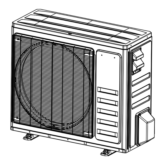
Installer's Guide
Side Discharge Heat Pump
5HPL5024A1000A
5HPL5036A1000A
5HPL5048A1000A
5HPL5060A1000A
N N o o t t e e : : The manufacturer recommends installing only approved matched indoor and outdoor systems. All of the manufacture's split
systems are AHRI rated only with TXV/EEV indoor systems. Some of the benefits of installing approved matched indoor and
outdoor split systems are maximum efficiency, optimum performance and the best overall system reliability.
Only qualified personnel should install and service the equipment. The installation, starting up, and servicing of heating, ventilating, and air-conditioning
equipment can be hazardous and requires specific knowledge and training. Improperly installed, adjusted or altered equipment by an unqualified person
could result in death or serious injury. When working on the equipment, observe all precautions in the literature and on the tags, stickers, and labels that
are attached to the equipment.
November 2024
S S A A F F E E T T Y Y W W A A R R N N I I N N G G
1 1 8 8 - - B B C C 1 1 2 2 4 4 D D 1 1 - - 1 1 A A - - E E N N
N N o o t t e e : : Graphics in this document are for representation
only. Actual model may differ in appearance.
Advertisement
Table of Contents

Related Manuals for Trane 5HPL5024A1000A


Summary of Contents for Trane 5HPL5024A1000A
- Page 1 Installer’s Guide Side Discharge Heat Pump 5HPL5024A1000A 5HPL5036A1000A 5HPL5048A1000A 5HPL5060A1000A N N o o t t e e : : Graphics in this document are for representation only. Actual model may differ in appearance. N N o o t t e e : : The manufacturer recommends installing only approved matched indoor and outdoor systems. All of the manufacture’s split systems are AHRI rated only with TXV/EEV indoor systems.
-
Page 2: Safety Section
Safety Section I I m m p p o o r r t t a a n n t t : : This document contains a wiring diagram W W A A R R N N I I N N G G and service information. - Page 3 S S a a f f e e t t y y S S e e c c t t i i o o n n W W A A R R N N I I N N G G W W A A R R N N I I N N G G H H A A Z Z A A R R D D O O U U S S V V O O L L T T A A G G E E ! ! H H I I G G H H L L E E A A K K A A G G E E C C U U R R R R E E N N T T ! !
-
Page 4: Table Of Contents
Table of Contents Unit Location Considerations ....5 Operation Mode Display....23 Setting Up the Unit . -
Page 5: Unit Location Considerations
Unit Location Considerations Figure 1. Outdoor unit dimensions (024 and 036 models) Table 2. Unit Dimensions (024 and 036 models) Model A/(in) B/(in) C/(in) D/(in) E/(in) F/(in) G/(in) H/(in) I/(in) J/(in) 5HPL5024A1 31.35 35.83 14.13 15.36 16.59 5.97 6.07 3.71 6.09 38.54 5HPL5036A1... - Page 6 U U n n i i t t L L o o c c a a t t i i o o n n C C o o n n s s i i d d e e r r a a t t i i o o n n s s Figure 2.
- Page 7 U U n n i i t t L L o o c c a a t t i i o o n n C C o o n n s s i i d d e e r r a a t t i i o o n n s s Table 4.
- Page 8 U U n n i i t t L L o o c c a a t t i i o o n n C C o o n n s s i i d d e e r r a a t t i i o o n n s s Table 6.
- Page 9 U U n n i i t t L L o o c c a a t t i i o o n n C C o o n n s s i i d d e e r r a a t t i i o o n n s s Table 8.
- Page 10 U U n n i i t t L L o o c c a a t t i i o o n n C C o o n n s s i i d d e e r r a a t t i i o o n n s s Table 9.
-
Page 11: Setting Up The Unit
U U n n i i t t L L o o c c a a t t i i o o n n C C o o n n s s i i d d e e r r a a t t i i o o n n s s Setting Up the Unit Table 11. -
Page 12: Refrigerant Line Considerations
Refrigerant Line Considerations Table 12. Required Refrigerant Line Length Determine required line length and lift. Total Line Length = ___________________________Ft. Total Vertical Change (lift) = ____________________Ft. Table 13. Refrigerant Line Insulation Important: The vapor line must always be insulated. DO NOT allow Vapor Line Liquid Line the Liquid Line and Vapor Line to come in direct (metal... - Page 13 R R e e f f r r i i g g e e r r a a n n t t L L i i n n e e C C o o n n s s i i d d e e r r a a t t i i o o n n s s Table 15.
- Page 14 R R e e f f r r i i g g e e r r a a n n t t L L i i n n e e C C o o n n s s i i d d e e r r a a t t i i o o n n s s Table 18.
-
Page 15: Refrigerant Line Connections
Refrigerant Line Connections Flare the Refrigerant Line Figure 4. Remove Burrs I I m m p p o o r r t t a a n n t t : : This side discharge unit comes with factory Pipe mechanical connections (flare). Unit will ship with stub tubes for brazing see Shaper following section. -
Page 16: Braze The Refrigerant Line
R R e e f f r r i i g g e e r r a a n n t t L L i i n n e e C C o o n n n n e e c c t t i i o o n n s s Braze the Refrigerant Line Figure 6. -
Page 17: Refrigerant Line Leak Check
Refrigerant Line Leak Check Table 21. Check For Leaks After completion of field piping for split systems, the field pipework shall be pressure tested with nitrogen and then vacuum tested prior to refrigerant charging. Important: • Under no circumstances shall potential sources of ignition be used in the searching for or detection of refrigerant leaks. •... -
Page 18: Evacuation And Servicing
Evacuation and Servicing Table 22. Evacuate the Refrigerant Lines and Indoor Coil Important: Do not open the service valves until the refrigerant lines and indoor coil leak check and evacuation are complete. Evacuate until the micron gauge reads no higher than 350 0350 microns, then close off the valve to the vacuum pump. -
Page 19: Service Valve
Service Valve Table 24. Open the Gas Service Valve Important: Leak check and evacuation must be completed before opening the service valves. Note: Do not vent into the atmosphere. Remove valve stem cap. Using an adjustable wrench, turn valve stem 1/4 turn Connection pipe nut counterclockwise to the fully open position. -
Page 20: Electrical - Low Voltage
Electrical - Low Voltage Notes: • Field installed electrical conduit is required at the low voltage wire entry point to prevent pests from entering into the control box resulting in PCB damage. • The use of color coded low voltage wire is recommended to simplify connections between the outdoor unit, the control, and the indoor unit. - Page 21 E E l l e e c c t t r r i i c c a a l l - - L L o o w w V V o o l l t t a a g g e e Table 27.
-
Page 22: Electrical - High Voltage
Electrical - High Voltage Table 29. High Voltage Power Supply W W A A R R N N I I N N G G L L I I V V E E E E L L E E C C T T R R I I C C A A L L C C O O M M P P O O N N E E N N T T S S ! ! F F a a i i l l u u r r e e t t o o f f o o l l l l o o w w t t h h i i s s W W a a r r n n i i n n g g c c o o u u l l d d r r e e s s u u l l t t i i n n p p r r o o p p e e r r t t y y d d a a m m a a g g e e , , s s e e v v e e r r e e p p e e r r s s o o n n a a l l i i n n j j u u r r y y , , o o r r d d e e a a t t h h . -
Page 23: Operation Mode Display
Operation Mode Display 1. S S i i d d e e D D i i s s c c h h a a r r g g e e O O p p e e r r a a t t i i o o n n M M o o d d e e D D i i s s p p l l a a y y : : the digital display will not be illuminated. - Page 24 O O p p e e r r a a t t i i o o n n M M o o d d e e D D i i s s p p l l a a y y Table 32.
-
Page 25: Start Up
Start Up Table 33. System Start Up Ensure Sections Refrigerant Line Connections through Electrical High Voltage have been completed. Set System Thermostat to OFF. Turn on disconnect(s) to apply power to the indoor and outdoor units. Wait one (1) hour before starting the unit if compressor crankcase heater is used and the Outdoor Ambient is below 70º F. Set system thermostat to ON. -
Page 26: System Charge Adjustment
System Charge Adjustment Table 34. Additional Refrigerant per Line Set Length Liquid pipe diameter 1/4" 3/8" Additional charge for ft pipe (R454B) 0.16OZ 0.32OZ 18-BC124D1-1A-EN... -
Page 27: Checkout Procedures
Checkout Procedures Final phases of this installation are the unit Operational and Checkout Procedures. To obtain proper performance, all units must be operated and charge adjustments made. Important: Perform a final unit inspection to be sure that factory tubing has not shifted during shipment. Adjust tubing if necessary so tubes do not rub against each other when the unit runs. -
Page 28: Unit Capacity Adjustment
Unit Capacity Adjustment This switch allows the capacity of the unit to be N N o o t t e e : : The dip switch should be adjusted only when the adjusted during installation. The default setting (SW1-2 unit is powered off. If the dip switch is activated at the digit end (down)) represents 100% capacity. -
Page 29: Troubleshooting
Troubleshooting C C A A U U T T I I O O N N C C a a u u t t i i o o n n ! ! I I f f o o n n e e o o f f t t h h e e f f o o l l l l o o w w i i n n g g c c o o n n d d i i t t i i o o n n s s o o c c c c u u r r s s , , s s w w i i t t c c h h o o f f f f t t h h e e p p o o w w e e r r s s u u p p p p l l y y i i m m m m e e d d i i a a t t e e l l y y a a n n d d c c o o n n t t a a c c t t y y o o u u r r d d e e a a l l e e r r f f o o r r f f u u r r t t h h e e r r a a s s s s i i s s t t a a n n c c e e : : •... - Page 30 T T r r o o u u b b l l e e s s h h o o o o t t i i n n g g When problem occur, please check the following points before contacting a repair company. Table 37.
-
Page 31: Pressure Curves
Pressure Curves COOLING PERFORMANCE CAN BE CHECKED WHEN THE OUTDOOR TEMP IS ABOVE 65 DEG F. TO CHECK COOLING PERFORMANCE, SELECT THE PROPER INDOOR CFM, ALLOW PRESSURES TO STABILIZE. MEASURE INDOOR WET BULB TEMPERATURE, OUTDOOR TEMPERATURE, DISCHARGE AND SUCTION PRESSURES. ON THE PLOTS LOCATE OUTDOOR TEMPERATURE (1); LOCATE INDOOR WET BULB (2);... - Page 32 P P r r e e s s s s u u r r e e C C u u r r v v e e s s PRESSURE CURVES for 5HPL5036A1 Heating@SCFM Cooling@SCFM 1400 1210 INDOOR ENTERING WET BULB INDOOR ENTERING WET BULB CURVES TOP TO BOTTOM CURVESTOP TO BOTTOM 80,...
- Page 33 P P r r e e s s s s u u r r e e C C u u r r v v e e s s PRESSURE CURVES for 5HPL5060A1 Cooling@SCFM Heating@SCFM 1830 1850 INDOOR ENTERING WET BULB INDOOR ENTERING WET BULB CURVESTOP TO BOTTOM 80, CURVES TOP TO BOTTOM...
-
Page 34: Refrigerant Circuit (Only For Reference)
Refrigerant Circuit (Only for Reference) Outdoor Indoor High-pressure cut-off valve Filter Electronic expansion valve Condenser Filter Thermal expansion valve Four-way valve High-pressure switch Safety plug Low-pressure switch Evaporator Compressor Liquid-vapor Pressure sensor Low-pressure cut-off valve separator 18-BC124D1-1A-EN... -
Page 35: Symbols
Symbols 18-BC124D1-1A-EN... - Page 36 About Trane and American Standard Heating and Air Conditioning Trane and American Standard create comfortable, energy efficient indoor environments for residential applications. For more information, please visit www.trane.com or www.americanstandardair.com. The AHRI Certified mark indicates company participation in the AHRI Certification program. For verification of individual certified products, go to ahridirectory.org.
Need help?
Do you have a question about the 5HPL5024A1000A and is the answer not in the manual?
Questions and answers