Table of Contents
Advertisement
ALL phases of this installation must comply with NATIONAL, STATE AND LOCAL CODES
IMPORTANT — This Document is customer property. Please return to service information pack and give this Installer's Guide to the homeowner
upon completion of work.
WARNING:
© 2008 Trane
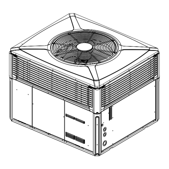
Installer's Guide
Single Package Heat Pump
16 SEER, Two Stage, Convertible
3, 4, & 5 Ton, R-410A
4WCZ6036A through 4WCZ6060A
HAZARDOUS VOLTAGE - DISCONNECT POWER and DISCHARGE
CAPACITORS BEFORE SERVICING
18-BB35-D1-3
4WCZ6-IG-3
Advertisement
Table of Contents

Related Manuals for Trane 4WCZ6036A


Summary of Contents for Trane 4WCZ6036A
- Page 1 ALL phases of this installation must comply with NATIONAL, STATE AND LOCAL CODES IMPORTANT — This Document is customer property. Please return to service information pack and give this Installer's Guide to the homeowner upon completion of work. 4WCZ6036A through 4WCZ6060A WARNING: HAZARDOUS VOLTAGE - DISCONNECT POWER and DISCHARGE CAPACITORS BEFORE SERVICING ©...
-
Page 2: Safety Considerations
Installer’s Guide Safety Considerations IMPORTANT: Read this entire manual before beginning installation procedures. Read this manual carefully before attempting to install, operate, or ▲ ▲ CAUTION perform maintenance on this unit. Installation and maintenance should be performed by qualified service technicians only. CONTAINS REFRIGERANT! SYSTEM CONTAINS OIL AND REFRIGERANT UNDER HIGH NOTE: "Warnings"... -
Page 3: Table Of Contents
Installer’s Guide Contents Introduction Safety Considerations Read this manual carefully before attempting to install, operate, Introduction or perform maintenance on this unit. Installation and maintenance Step 1-Inspect Shipment should be performed by qualified service technicians only. This Step 2-Determine Unit Clearances unit is listed by Underwriters Laboratory. -
Page 4: Step 2-Determine Unit Clearances
Installer’s Guide Step 2—Determine Unit Clearances Figures 1 through 6 show the unit critical dimensions. NOTE: The view labeled “Bottom Side” represents the Base as viewed looking up from underneath the unit. Figure 1. 4WCZ6036A (1 of 3) Page 4... - Page 5 Installer’s Guide Figure 2. 4WCZ6036A (2 of 3) Page 5...
- Page 6 Installer’s Guide Figure 3. 4WCZ6036A (3 of 3) Page 6...
- Page 7 Installer’s Guide NOTE: The view labeled “Bottom Side” represents the Base as viewed looking up from underneath the unit. Figure 4. 4WCZ6048A through 4WCZ6060A (1 of 3) Page 7...
- Page 8 Installer’s Guide Figure 5. 4WCZ6048A through 4WCZ6060A (2 of 3) Page 8...
- Page 9 Installer’s Guide Figure 6. 4WCZ6048A through 4WCZ6060A (3 of 3) Page 9...
-
Page 10: Step 3-Review Location And Recommendation Information
Installer’s Guide Step 3—Review Location and Recommendation Information Down Airflow Units ▲ ▲ CAUTION 1. Location of the unit must allow service clearance around it to Caution must be taken at all times to avoid personal injuries ensure adequate serviceability, maximum capacity, and peak and/or damage to equipment. -
Page 11: Step 4-Unit Installation
Installer’s Guide Step 4—Unit Installation NOTE: The unit is shipped for horizontal installation. Rooftop Installation -- Curb Mounting Convert Horizontal Airflow to Down Airflow Ground Level Installation The factory ships the unit for horizontal airflow. Perform this To install the unit at ground level: procedure to convert it to down airflow: 1. -
Page 12: Placing The Unit On The Mounting Curb
Installer’s Guide Figure 8. Converting Horizontal to Down Airflow 2. Insert the four (4) lifting lugs in the openings provided in the drip NOTE The ductwork is installed as part of the curb installation. lip on each end of the unit. See Figure 9 inset B, page 13. A Do not attach ductwork to the unit and lower the unit with tap or jerk to the lug will overcome the interference that arises ductwork onto the curb. - Page 13 Installer’s Guide IMPORTANT: To prevent damage to the sides and top of the unit when hoisting, retain the top shipping skid on the unit or use “spreader bars” as Base of unit Drip lip on shown in these illustrations. rest on top of perimeter of curb rails unit...
- Page 14 Installer’s Guide Figure 11. Typical Rooftop Horizontal Airflow Application with Frame Figure 12. Typical Rooftop Down Airflow Application with Frame Page 14...
-
Page 15: Ductwork Installation
Installer’s Guide Ductwork Installation Attaching Downflow Ductwork to Roof Curb UNIT EXTERIOR Supply and return air flanges are provided on the roof curb for easy WEATHERPROOF duct installation. All ductwork must be run and attached to the curb THIS SEAM before the unit is set into place. -
Page 16: Air Filter Installation
Installer’s Guide To connect power to the unit: Air Filter Installation 1. Remove the Control access panel. Pass the power The 4WCZ6 heating/cooling unit requires an air filter. A filter frame wires through the Power Entry hole in the end of the unit. accessory is offered that will allow the installation of a filter within See Figure 16 below. -
Page 17: Field Wiring Diagram
Installer’s Guide NOTES: 1. FUSED DISCONNECT SIZE, POWER WIRING AND GROUNDING OF EQUIPMENT MUST COMPLY WITH CODES. 2. BE SURE POWER SUPPLY AGREES WITH EQUIPMENT AND HEATER NAMEPLATE. 3. LOW VOLTAGE WIRING TO BE 18 AWG MINIMUM CONDUCTOR. 4. SEE HEATER NAMEPLATE FOR CURRENT RATING OF HEATER USED. -
Page 18: Control Wiring (Class Ii)
Installer’s Guide Are all covers and access panels in place to prevent air loss and Control Wiring (Class II) safety hazards? Low voltage control wiring should not be run in conduit with power wiring unless Class 1 wire of proper voltage rating is used. Route Starting the Unit in Cooling Mode the thermostat cable or equivalent single leads of No. -
Page 19: Starting The Unit In Heating Mode
Installer’s Guide Sequence of Operation The energized compressor contactor (CC) completes the General circuit to the compressor for 1 stage (Low) operation and Operation of the unit heating and cooling cycles is automatic when the outdoor single speed fan motor (ODM). The indoor fan the system is set to HEAT or COOL (the optional automatic motor (ECM) will operate on low speed. -
Page 20: Ecm Fan Motor Adjustment
Installer’s Guide ECM Fan Motor Adjustments Maintenance If the airflow needs to be increased or decreased, see the Owner Maintenance Airflow Table in the SERVICE FACTS. Information on changing the speed of the blower motor is in the Blower Performance Some of the periodic maintenance functions of the 4WCZ6 unit can Table. -
Page 21: Warranty Information
Models Less Than 20 Tons for Residential Use* This limited warranty is extended by Trane U.S. Inc., to the original purchaser and to any succeeding owner of the real property to which the Heat Pump is originally affixed, and applies to products purchased and retained for use within the U.S.A. - Page 22 Models Less Than 20 Tons for Commercial Use* This warranty is extended by Trane U.S. Inc., to the original purchaser and to any succeeding owner of the real prop- erty to which the Heat Pump is originally affixed, and applies to products purchased and retained for use within the U.S.A.
- Page 23 Installer’s Guide Page 23...
- Page 24 Installer’s Guide Trane 6200 Troup Highway Tyler, TX 75707-9010 The manufacturer has a policy of continuous product and product data improvement, © 2008 Trane and it reserves the right to change design and specification without notice. Page 24...
Need help?
Do you have a question about the 4WCZ6036A and is the answer not in the manual?
Questions and answers