Table of Contents
Advertisement
Service Manual
RoHS
This product does not contain any hazardous substances prohibited by the RoHS Directive.
(You will find 'RSF' mark near the rating plate on the RoHS compliant product.)
WARNING
* You are requested to use RoHS compliant parts for maintenance or repair.
* You are requested to use lead-free solder.
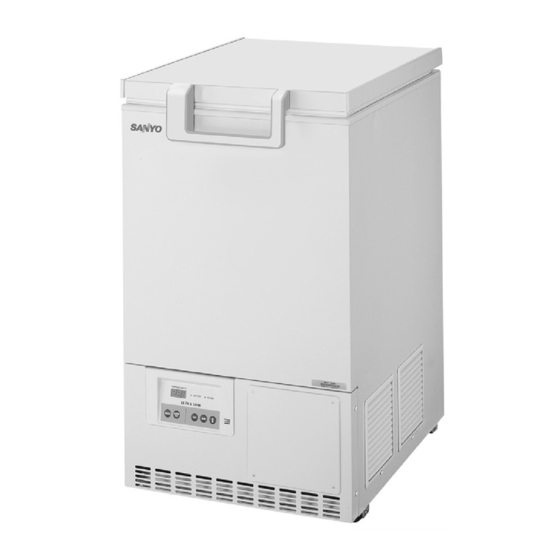
Ultra-Low Temperature Freezer
MDF-C8V
FILE No.
SANYO Electric Co., Ltd.
Biomedical Business Unit
Advertisement
Chapters
Table of Contents

Related Manuals for Sanyo MDF-C8V


Summary of Contents for Sanyo MDF-C8V
- Page 1 Service Manual FILE No. Ultra-Low Temperature Freezer MDF-C8V SANYO Electric Co., Ltd. Biomedical Business Unit RoHS This product does not contain any hazardous substances prohibited by the RoHS Directive. (You will find ‘RSF’ mark near the rating plate on the RoHS compliant product.) WARNING * You are requested to use RoHS compliant parts for maintenance or repair.
- Page 2 Effective models This service manual is effective following models. Model name Product code Voltage and Frequency MDF-C8V 823 187 51 115V 60Hz 823 187 52 220/230/240V 50Hz...
-
Page 3: Table Of Contents
Contents P a g e F e a t u r e s - - - - - - - - - - - - - - - - - - - - - - - - - - - - - - - - - - - - - - - - - - - - - - - - - - - - - S p e c i f i c a t i o n s - - - - - - - - - - - - - - - - - - - - - - - - - - - - - - - - - - - - - - - - - - - - - - - - - - - - - - S t r u c t u r a l s p e c i f i c a t i o n s... -
Page 4: Features
Features Space saving freezer for personal use ‘Glass wool’ core is newly adopted for insulation Width 550mm for minimal installation Suitable internal dimensions for inventory racks 6 pcs of inventory rack (IR-207C) * * 5pcs of inventory rack when Back-up kit (CVK-UB4) installed Ensure preservation Selectable high temperature alarm Setting temperature can be kept by remote alarm terminal and non-volatile memory... -
Page 5: Specifications
Specifications Structural specifications Item Specifications External dimensions W 550 × D 685 × H 945 mm Internal dimensions W 405 × D 490 × H 425 (mm) Effective capacity 84 L Exterior Painted steel Interior Painted steel Door Painted steel Insulation Cabinet;... -
Page 6: Control Specifications
Control specifications Item Specifications Cooling performance (1/2H temp, AT 30 , no load) Temperature control range -60 ~-80 (AT5~30 , no load) Temperature controller Microprocessor controlled system: Key-pad input Temperature set range: -55 ~-85 increment) Set value kept in non-volatile memory Temperature sensor Pt.1000 Temperature display... -
Page 7: Performance Specifications
Performance specifications Cooling performance (ambient temperature; 30 ,no load) Temperature control range to -80 (ambient temperature; 30 ,no load) Rated voltage AC110V AC115V AC220V AC230V AC240V AC220V Rated frequency 60Hz 60Hz 50Hz 50Hz 50Hz 60Hz Rated power consumption 295W 300W 310W 325W 350W... -
Page 8: Dimensions
Dimensions... -
Page 9: Refrigeration Circuit Diagram
Refrigeration circuit diagram... -
Page 10: Refrigeration Circuit Welding Points
Refrigeration circuit welding points Place to fit AT sensor Place to fit AT sensor Ex. capillary Ex. tank... -
Page 11: Cooling Unit Parts
Cooling unit parts <MDF-C8V> Item Specifications Compressor 115V, 60Hz Type: C-2SN400L2W Compressor code: 807 780 22 220/230/240V,50Hz Type: C-2SN400L5W Compressor code: 807 780 25 Refrigerant oil Ze-NIUS32SA Charged q’ty: 280cc Cooling system Forced air cooling Condenser Type Finless tube Cascade condenser... -
Page 12: Components On Pcb
Components on PCB... -
Page 13: E L E C T R I C A L P A R T
Electrical Parts MDF-C8V AC115V, 60Hz AC220/230/240V, 50Hz Type C-2SN400L2W C-2SN400L5W Compressor Compressor code 807 780 22 807 780 25 Rated voltage (50/60Hz) 1, 110~115V, 60Hz 1, 220~240V, 50/60Hz Winding resistance C-S(Aux) 5.432 18.79 C-R(Main) 1.824 6.251 Type AMVL-180A AMVL-300A Starting relay... - Page 14 Specification of sensor Following shows the relation between temperatures of temp. sensor (Pt1000 ) and resistance value. Temperature Resistance Temperature Resistance -170 326.92 885.13 -160 368.57 923.55 -150 409.87 961.84 -140 450.83 1000.0 -130 491.47 1038.0 -120 531.83 1076.0 -110 571.92 1113.8 -100...
-
Page 15: W I R I N G D I A G R A
Wiring diagram... -
Page 16: C I R C U I T D I A G R A
Circuit diagram... -
Page 17: Connection On Pcb
Connection on PCB Following is the explanation of connections on Main PCB. Connector Connects to Usage Voltage Switching power supply To supply the power to PCB #1:12V MTR-480 Option To connect with interface Remote alarm terminal #1: COM. Output for remote alarm contact #2: N.O. - Page 18 Control specification Key and Switch BUZZER In alarm condition, buzzer stops sounding with this key pressed. Remote alarm output and alarm message would not be off. During the power failure (battery back-up), press the key to show the present temperature of PT sensor. ALARM TEST With this key pressed to activate alarm test mode to be forcibly step into alarm condition (ALARM lamp blinks, intermittent buzzer beeps, digital LED...
- Page 19 B) Function mode Setting range : 00~33 Display range 00~39 00, 04, 08, 13, 15, 16, 18, 19, 20, 26, 27, 31 and 33 are unavailable. Setting procedure : In PV display, keep pressing key over 5 seconds to enter function mode (F00 is displayed).
- Page 20 Function mode Automatically revert to PV display (high temp. alarm SV) setting (low temp. alarm SV) setting Battery accumulating time display Automatically revert to PV display Compressor delay time setting Service code input (code: 384) F07 * Temperature Zero Adjustment F08 * Automatically revert to PV display F09 *...
- Page 21 F04: <Purpose> Simply passing through if entered by mistake. <Operation> Press SET key in “F04” displayed to revert to PV display. F05: <Purpose> Compressor is turned on with forcibly delayed (by minute increment) when the power retrieves from the power failure. <Operation>...
- Page 22 Press SET key to store and revert to PV display. Model code ‘003’: MDF-C8V F18: <Purpose> Simply passing through if entered by mistake. <Operation> Press SET key in “F18” displayed to revert to PV display. Buzzer tone is emitted if service code is not input in F06.
- Page 23 F25: <Purpose> Alarm auto recovery time setting <Operation> Input F25 and press SET key to display “030” (initial). Change to the desired value with key and key. Press SET key to store the value and revert to PV display. 000: Auto recovery OFF 040: Recovers after 40min.
- Page 24 Remote alarm terminal In normal condition: Remote alarm contact: N.O. N.C. In alarm condition & Remote alarm contact: N.C. N.O. power failure Sensor failure (1) Temp. sensor Open circuit: E01 and 50 are displayed alternately, the buzzer beeps intermittently and remote alarm contact outputs. The compressor would be allowed to turn on.
- Page 25 Fan motor operation and compressor protection Fan motor operation : 1.When the temperature in Comp. sensor is lower than 20 ; Fan motor turns off with the power supplied Turns on when the temperature in Comp. sensor is higher than 80 Turns off when the temperature in Comp.
-
Page 26: Parts Layout
Parts layout Temp. sensor PT-1000> MDF-C8V Comp.sensor <Fan> <Battery> <Control panel> Battery cover <Back side of Control panel> Display PCB Control PCB... - Page 27 <How to access the Main PCB> 1. Catch the pick by screwdriver to pull the panel out. 2.Loosen tie band to set cables free. Pull Electric BOX out carefully. Electric BOX <Main PCB layout> Switching power supply...
- Page 28 <Lower back side> <Remote alarm> Battery switch Ex.tank Starting relay Temp.control relay Fan relay Starting capacitor Power cord Running capacitor Breaker switch...
-
Page 29: Test Data
Test Data Note: All data is the reference only. -
Page 33: Collection And Charge Of Refrigerant
Collection and charge of refrigerant 1. Preparation * Refrigerant [MU-N48] * Connector for charging pipe (if necessary) 2. Procedures 1) Pull vacuum in refrigeration circuit Pull vacuum by pump for approx. 5 minuites. <NOTE> It is important to pull vacuum in the circuit to avoid possibility causing fire by residual refrigerant (R-600). - Page 34 3) Charge of refrigerant Stop vacuum pump operation. Open the valve of tank to charge refrigerant with approx. 0.2~0.5 Mpa/G. 4) Pipe pinching in High pressure side Charge refrigerant until pressure is reached to 1.6MPa/G. Close the valve of tank. Hold charging pipe by pliers to pinch it off by pinch pliers.
- Page 35 Instruction manual This section is extracted and printed from Instruction Manual. If you find out “Refer to page ” in them, this page means not page in service manual but page in the lower corner of each page in the extract from Instruction manual. This page number is not corresponded with serial number in Service manual.
- Page 36 INSTRUCTION MANUAL MDF-C8V Ultra-Low Temperature Freezer...
-
Page 37: I N S T R U C T I O N M A N U A
CONTENTS INTRODUCTION P. 2 PRECAUTIONS FOR SAFE OPERATION P. 3 ENVIRONMENTAL CONDITIONS P. 7 FREEZER COMPONENTS P. 8 Control panel P. 10 INSTALLATION SITE P. 11 INSTALLATION P. 12 START-UP OF UNIT P. 13 CHAMBER TEMPERATURE SETTING P. 14 KEY LOCK FUNCTION P. -
Page 38: Introduction
Contact Sanyo sales representative or agent if any page of the manual is lost or page order is incorrect. Contact Sanyo sales representative or agent if any point in this manual is unclear or if there are any inaccuracies. -
Page 39: Precautions For Safe Operation
PRECAUTIONS FOR SAFE OPERATION It is imperative that the user complies with this manual as it contains important safety advice. Items and procedures are described so that you can use this unit correctly and safely. If the precautions advised are followed, this will prevent possible injury to the user and any other person. - Page 40 PRECAUTIONS FOR SAFE OPERATION WARNING Do not use the unit outdoors. Current leakage or electric shock may result if the unit is exposed to rain water. Only qualified engineers or service personnel should install the unit. The installation by unqualified personnel may cause electric shock or fire. Install the unit on a sturdy floor and take an adequate precaution to prevent the unit from turning over.
- Page 41 PRECAUTIONS FOR SAFE OPERATION WARNING Ensure you do not inhale or consume medication or aerosols from around the unit at the time of maintenance. These may be harmful to your health. Never splash water directly onto the unit as this may cause electric shock or short circuit. Never put containers with liquid on the unit as this may cause electric shock or short circuit when the liquid is spilled.
- Page 42 PRECAUTIONS FOR SAFE OPERATION CAUTION Use a dedicated power source (a dedicated circuit with a breaker) as indicated on the rating label attached to the unit. A branched circuit may cause fire resulting from abnormal heating. Connect the power supply plug to the power source firmly after removing the dust on the plug. A dusty plug or improper insertion may cause a heat or ignition.
-
Page 43: Environmental Conditions
ENVIRONMENTAL CONDITIONS This equipment is designed to be safe at least under the following conditions (based on the IEC 1010-1): Indoor use; Altitude up to 2000 m; Ambient temperature 5 C to 40 Maximum relative humidity 80% for temperature up to 31 C decreasing linearly to 50% relative humidity at 40 Mains supply voltage fluctuations not to exceed... -
Page 44: Freezer Components
FREEZER COMPONENTS... - Page 45 FREEZER COMPONENTS 1. Lock: By turning to 180 degree to clockwise with a key, the door can be locked. 2. Door: Top hinged type. To open the door, grip the handle. 3. Magnetic door gasket: Seals the door and prevents leakage of cold air. 4.
-
Page 46: Control Panel
ON gets the alarm lamp to flash, the remote alarm to operate, and the buzzer to sound. 8. Battery check lamp (BATTERY): This lamp lights to recommend the battery replacement. For the replacement, consult Sanyo sales representative or agent. -
Page 47: Installation Site
INSTALLATION SITE To operate this unit properly and to obtain maximum performance, install the unit in a location with the following conditions: A location not subjected to direct sunlight Do not install the unit under direct sunlight. Installation in a location subjected to direct sunlight cannot obtain the intended performance. -
Page 48: Installation
INSTALLATION 1. Removing the packaging materials and tapes Remove all transportation packaging materials and tapes. Open the doors and ventilate the unit. If the outside panels are dirty, clean them with a diluted neutral dishwashing detergent. (Undiluted detergent can damage the plastic components. For the dilution, refer to the instruction of the detergent.) After the cleaning with the diluted detergent, always wipe it off with a wet cloth. -
Page 49: Start-Up Of Unit
START-UP OF UNIT Follow the procedures for the initial and consequent operations of the unit. 1. Connect the power cord to the dedicated outlet having appropriate rating with the chamber empty. 2. Turn off the power switch of the back-up system (optional component) if it is installed. 3. -
Page 50: Chamber Temperature Setting
CHAMBER TEMPERATURE SETTING Table 1 shows the basic procedure for setting the chamber temperature. Perform key operations in the sequence indicated in the table. The example in the table is based on the assumption that the desired temperature is -75 Note: The chamber temperature is set to -80 C at the factory. -
Page 51: Alarm Temperature Setting
ALARM TEMPERATURE SETTING This unit is provided with the high and low temperature alarm and the temperature at which the alarm is activated is changeable. The following procedure shows the setting of alarm temperature according to the condition below: High temperature alarm: activates at the temperature 5 C higher than the chamber set temperature Low temperature alarm: activates at the temperature 5 C lower than the chamber set temperature... - Page 52 ALARM TEMPERATURE SETTING Table 4 Procedure for setting low temperature alarm Description of operation Key operated Indication after operation ---- The current chamber temperature is ----- displayed. Press numerical value shift key for The right digit is flashed. 5 seconds. Press numerical value shift key and When pressed, the figure of settable scroll the figure to 2.
-
Page 53: Setting Of Alarm Resume Time
SETTING OF ALARM RESUME TIME The alarm buzzer is silenced by pressing alarm buzzer stop key (BUZZER) key on the control panel during alarm condition (The remote alarm is not silenced). The buzzer will be activated again after certain suspension if the alarm condition is continued. The suspension time can be set by following the procedure shown in the Table 5 below. -
Page 54: Change Of Compressor Delay Time
CHANGE OF COMPRESSOR DELAY TIME The delay time of the compressor can be changed to reduce the load on the power line and to facilitate the start-up (reset) of the freezer after power failure. The example in the table is based on the assumption that the delay time is changed to 4 minutes. The delay time is set in 2 minutes at the factory. -
Page 55: Remote Alarm Terminal
REMOTE ALARM TERMINAL WARNING Always disconnect the power supply cord before connecting an alarm device to the remote alarm terminal. The terminal of the remote alarm is installed at the back of the unit. The alarm is generated from this terminal. -
Page 56: Alarms & Safety Functions
ALARMS & SAFETY FUNCTIONS This unit has the alarms and safety functions shown in Table 7, and also self diagnostic functions. Table 7 Alarms and safety functions Alarm & Safety Situation Indication Buzzer Safety operation If the chamber temperature is higher Alarm lamp is flashed. -
Page 57: Routine Maintenance
ROUTINE MAINTENANCE WARNING Always disconnect the power supply to the unit prior to any repair or maintenance of the unit in order to prevent electric shock or injury. Ensure you do not inhale or consume medication or aerosols from around the unit at the time of maintenance. -
Page 58: Battery
The buzzer can not be activated at the power failure and the stored items may be influenced if the battery is left as it is for more than 3 years. It is recommended that the battery is replaced ahead of time. For the replacement of the battery, contact Sanyo sales representative or agent. -
Page 59: Replacement Of Battery
REPLACEMENT OF BATTERY Location of a nickel-metal-hydride battery This unit is provided a nickel-metal-hydride battery for the power failure warning device. The battery is located at the back of the control panel. (Fig. 1) The high voltage components are enclosed in the electrical box. The cover should be removed by a qualified engineer or a service personnel only to prevent the electric shock.. -
Page 60: Troubleshooting
Note: If the malfunction is not eliminated after checking the above items, or the malfunction is not shown in the above table, contact Sanyo sales representative or agent. CAUTION The noise of refrigerant flow may be heard due to the characteristic of refrigerating circuit. Especially for several hours after start-up, the noise of motor compressor or refrigerant flow can be larger. -
Page 61: Disposal Of Unit
DISPOSAL OF UNIT WARNING If the unit is to be stored unused in an unsupervised area for an extended period ensure that children do not have access and doors cannot be closed completely. The disposal of the unit should be accomplished by appropriate personnel. Always remove doors to prevent accidents such as suffocation. - Page 62 Waste Electrical and Electronic Equipment (WEEE) Directive-2002/96/EC (English) Your SANYO product is designed and manufactured with high quality materials and components which can be recycled and reused. This symbol means that electrical and electronic equipment, at their end-of-life, should be disposed of separately from your household waste.
- Page 63 DISPOSAL OF UNIT (French) Votre produit Sanyo est conçu et fabriqué avec des matèriels et des composants de qualité supérieure qui peuvent être recyclés et réutilisés. Ce symbole signifie que les équipements électriques et électroniques en fin de vie doivent être éliminés séparément des ordures ménagères.
- Page 64 Por favor, ajude-nos a conservar o ambiente em que vivemos! (Italian) Il vostro prodotto SANYO è stato costruito da materiali e componenti di alta qualità, che sono riutilizzabili o riciclabili. Prodotti elettrici ed elettronici portando questo simbolo alla fine dell’uso devono essere smaltiti separatamente dai rifiuti casalinghi.
- Page 65 Alstublieft help allen mee om het milieu te beschermen. (Swedish) Din SANYO produkt är designad och tillverkad av material och komponenter med hög kvalitet som kan återvinnas och återanvändas. Denna symbol betyder att elektriska och elektroniska produkter, efter slutanvändande, skall sorteras och lämnas separat från Ditt hushållsavfall.
-
Page 66: Temperature Recorder (Option)
MTR-85H or MTR-G85. For the attachment, optional component is necessary as follows. Temperature recorder Mounting kit Recorder sensor cover MTR-85H MDF-S3085 MTR-C8 MTR-G85 ----- MTR-C8 For the installation of the temperature recorder, contact Sanyo sales representative or agency. Space for temperature recorder... -
Page 67: Installation Of Mtr-85H
TEMPERATURE RECORDER (OPTION) Installation of MTR-85H 1. Remove 4 screws (A, B, C, D) on the side of the front panel to take off the front panel. Then remove 4 Front panel screws on the cover for the recorder mounting space and take off the cover (Fig. - Page 68 TEMPERATURE RECORDER (OPTION) 6. Attach the sensor cover to the right side of the chamber with 2 screws on the chamber wall (Fig. 4) Fig. 4 7. Seal the access port on the outside with putty as shown in Fig. 5. Putty 8.
-
Page 69: Installation Of Mtr-G85
TEMPERATURE RECORDER (OPTION) Installation of MTR-G85 1. Remove 4 screws (A, B, C, D) on the side of the front panel to take off the front panel. Then remove 4 Front panel screws on the cover for the recorder mounting space and take off the cover (Fig. - Page 70 TEMPERATURE RECORDER (OPTION) 6. Attach the sensor cover to the right side of the chamber with 2 screws on the chamber wall (Fig. 4) 7. Seal the access port on the outside with putty as shown in Fig. 5. 9. Replace the front panel and fix it with 4 screws. 10.
-
Page 71: Back-Up System (Option)
BACK-UP SYSTEM (OPTION) This freezer can be provided with a back-up system (CVK-UB4) which is available as an optional component. For the installation, refer to the instruction manual enclosed with the system. BACK UP STANDBY BATTERY CVK-UB4 control panel CVK-UB4 switch box 1. - Page 72 Liquid CO cylinder to the joint of the back-up system. For gas cylinder this setting, consult with a qualified gas supplier or Sanyo sales agency. 2. After setting the liquid CO gas cylinder, operate the freezer until the chamber temperature reaches the required level.
-
Page 73: Specifications
SPECIFICATIONS Name Ultra-Low Temperature Freezer Model MDF-C8V External dimensions W550 x D685 (+83)* x H945 (mm) Internal dimensions W405 x D490 x H425 (mm) Effective capacity 84 L Exterior Painted steel Interior Painted steel Door Painted steel Access port Diameter 17 mm, back side, bottom Cabinet;... -
Page 74: Performance
PERFORMANCE Cooling performance C (ambient temperature; 30 C, no load) Temperature control range C to -80 C (ambient temperature; 30 C, no load) Rated voltage AC 110 V AC 115 V AC 220 V AC 230V AC 240V AC 220V Rated frequency 60 Hz 60 Hz... -
Page 75: Safety Check Sheet
Procedure to be adhered to in order to reduce safety risk indicated in b) below. Date : Signature : Address, Division : Telephone : Product name: Model: Serial number: Date of installation: MDF-C8V Ultra-low temperature reezer Please decontaminate the unit yourself before calling the service engineer. - Page 76 CVK-UB4 INSTRUCTION MANUAL CVK-UB4(I) Back-up System for Ultra-Low Temperature Freezer...
- Page 77 CONTENTS INTRODUCTION P. 2 PRECAUTIONS FOR SAFE OPERATION P. 3 COMPONENTS LIST P. 5 INSTALLATION Assembling of the solenoid valve P. 8 Installation of the door switch P. 9 installation of the back-up kit P.10 Wiring P.12 CONTROL PANEL P.13 TRIAL OPERATION P.14 Calibration...
-
Page 78: Introduction
Contact Sanyo sales representative or agent if any page of the manual is lost or page order is incorrect. Contact Sanyo sales representative or agent if any point in this manual is unclear or if there are any inaccuracies. -
Page 79: Precautions For Safe Operation
PRECAUTIONS FOR SAFE OPERATION It is imperative that the user complies with this manual as it contains important safety advice. Items and procedures are described so that you can use this unit correctly and safely. If the precautions advised are followed, this will prevent possible injury to the user and any other person. - Page 80 PRECAUTIONS FOR SAFE OPERATION WARNING Only qualified engineers or service personnel should install this system. The installation by unqualified personnel may cause electric shock or fire. Turn off the all switches and disconnect the power supply to the ultra low temperature freezer prior to the attachment of the back-up system in order to prevent electric shock or injury.
-
Page 81: Components List
COMPONENTS LIST Confirm that the accessories of the table 1 are gathered. Report it to the dealer or the sales if there is a problem in packing of the product. Table 1 PARTS NAME Q’ TY APPEARANCE THE EXPLANATION OF THE USE PLATE MTG A The plate fixes a solenoid valve cover. - Page 82 COMPONENTS LIST The continuation of the table 1 PARTS NAME Q’ TY APPEARANCE THE EXPLANATION OF THE USE LABEL It is put near the connection place. DOOR SWITCH This assy connected a door switch and ASS’Y two indicator lamps (green and orange). It is the lamp turned on with a power INDICATOR switch of the back-up system.
- Page 83 COMPONENTS LIST The continuation of the table 1 PARTS NAME Q’ TY APPEARANCE THE EXPLANATION OF THE USE WIRING ASS’Y It is harness to install on the electric box of the freezer (option). NYLON CLIP 6N Wiring ass’y DS is fixed. NYLON CLIP 7N Wiring ass’y BP is fixed.
-
Page 84: Installation
INSTALLATION Assembling of the solenoid valve 1. The joint nut on the outlet side of the CO solenoid valve is removed. The valve outlet pipe with the pipe insulation is inserted into the joint nut, and fastened in the joint. (Fig. 1) Fasten a joint part securely so that CO gas can not leak out. -
Page 85: Installation Of The Door Switch
INSTALLATION Installation of the door switch Spacer and a door switch mounting plate are fixed on the hole of the left side (upside) of the freezer with two screws E (M5 x 16 pan head). (Fig. 1) Screw D Shim for door switch Door switch Door switch cover Shim for door switch... -
Page 86: Installation Of The Back-Up Kit
INSTALLATION Installation of the back-up kit The slit (bottom right rear side) which freezer is being fitted up with, a rear cover, a sensor cover, the rubber cap of the access port and insulation inside the access port are taken out. 2. - Page 87 INSTALLATION 6. The sensor cover inside freezer chamber is removed, and the thermostat sensor part of the back-up system is inserted into the hole under freezer temperature style sensor. The hole of the neighborhood of the thermostat sensor part which inserted (A hole does not open an access port. Therefore, make a hole in the plus driver.) into freezer inside and the rear side is stopped with silicon.
-
Page 88: Wiring
INSTALLATION Wiring 1. Harness (a white connector) from the solenoid valve is connected to the connector of the upper same color of the back-up system. 2. It passes through the wiring ass’y DS (one white connector and two red connectors) from the door switch ass’y from the outside of the solenoid, and each upper of the back-up system ass’y is connected with the connector of the same color. -
Page 89: Control Panel
CONTROL PANEL BACK UP STANDBY BATTERY Control panel for CVK-UB4 Door switch ass’y for CVK-UB4 1. Power switch of back-up system (BACKUP) When turning on the system, the back-up stand-by on the door switch ass’y is brightened. This means that the system is ready. When this switch is turned off, the operation of the back-up system stops, and a back-up stand-by lamp turns off the lights. -
Page 90: Trial Operation
TRIAL OPERATION Following is the procedures for the trial operation of the back-up system. Read an instruction manual enclosed with a ultra-low temperature freezer carefully before the trial operation. 1. Check that the gas cylinder connect pipe is connected properly between the LCO solenoid valve and the gas cylinder. -
Page 91: Specifications
The battery for power failure alarm is an article for consumption. It is recommended that the battery will be replaced about every 3 years. Contact Sanyo sales representation or agent at the time of replacement of the battery for recycling. - Page 92 JK1659-150B...
Need help?
Do you have a question about the MDF-C8V and is the answer not in the manual?
Questions and answers