Table of Contents
Advertisement
Advertisement
Table of Contents

Subscribe to Our Youtube Channel
Related Manuals for Sanyo MDF-C2156VAN


Summary of Contents for Sanyo MDF-C2156VAN
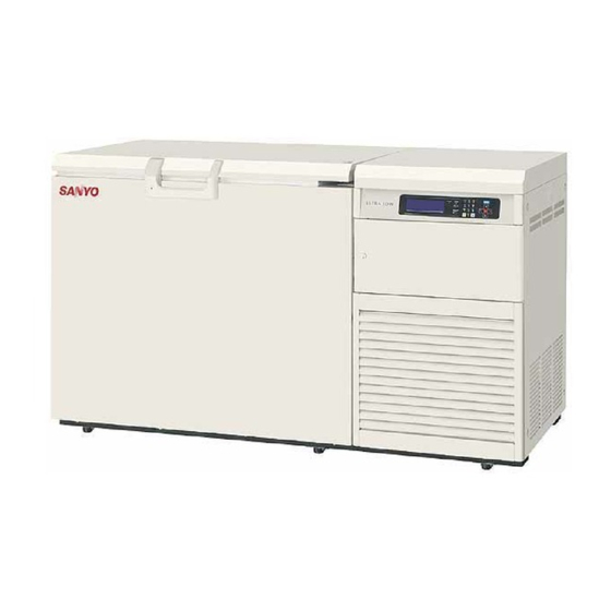
- Page 1 INSTRUCTION MANUAL MDF-C2156VAN MDF-C2156VANC Ultra-Low Temperature Freezer...
-
Page 2: Table Of Contents
CONTENTS INTRODUCTION P. 2 PRECAUTIONS FOR SAFE OPERATION P. 3 ENVIRONMENTAL CONDITIONS P. 7 FREEZER COMPONENTS P. 8 Control panel P. 11 INSTALLATION SITE P. 12 INSTALLATION P. 13 START-UP OF UNIT P. 14 Operation after power failure P. 14 BASIC SCREEN OF CONTROL PANEL P. -
Page 3: Introduction
■ Contact Sanyo sales representative or agent if any page of the manual is lost or page order is incorrect. ■ Contact Sanyo sales representative or agent if any point in this manual is unclear or if there are any inaccuracies. -
Page 4: Precautions For Safe Operation
PRECAUTIONS FOR SAFE OPERATION It is imperative that the user complies with this manual as it contains important safety advice. Items and procedures are described so that you can use this unit correctly and safely. If the precautions advised are followed, this will prevent possible injury to the user and any other person. - Page 5 PRECAUTIONS FOR SAFE OPERATION WARNING Do not use the unit outdoors. Current leakage or electric shock may result if the unit is exposed to rain water. The installation by Only qualified engineers or service personnel should install the unit. unqualified personnel may cause electric shock or fire. Install the unit on a sturdy floor and take an adequate precaution to prevent the unit from turning over.
- Page 6 PRECAUTIONS FOR SAFE OPERATION WARNING Ensure you do not inhale or consume medication or aerosols from around the unit at the time of maintenance. These may be harmful to your health. Never splash water directly onto the unit as this may cause electric shock or short circuit. Never put cylinders with liquid on the unit as this may cause electric shock or short circuit when the liquid is spilled.
- Page 7 PRECAUTIONS FOR SAFE OPERATION CAUTION Use a dedicated power source (a dedicated circuit with a breaker) as indicated on the rating label attached to the unit. A branched circuit may cause fire resulting from abnormal heating. Connect the power supply plug to the power source firmly after removing the dust on the plug. A dusty plug or improper insertion may cause a heat or ignition.
-
Page 8: Environmental Conditions
ENVIRONMENTAL CONDITIONS This equipment is designed to be safe at least under the following conditions (based on the IEC-1010-1): ■ Indoor use; ■ Altitude up to 2000 m; ■ Ambient temperature 5 C to 40 ■ Maximum relative humidity 80% for temperature up to 31 C decreasing linearly to 50% relative humidity at 40 ■... -
Page 9: Freezer Components
FREEZER COMPONENTS Rear side Inside of side table... - Page 10 FREEZER COMPONENTS 1. Lock: Turn clockwise to 180 with a key and the outer door is securely locked. 2. Door: Hinged type. The door can be opened in any angle on the way to full open. 3. Magnetic door gasket: Seals the door and prevents leakage of cold air. 4.
- Page 11 FREEZER COMPONENTS 21. Remote alarm switch (REMOTE ALARM): This switch is for remote alarm. In case of operating remote alarm, turn on the switch. 22. Remote alarm terminal (MAX DC30V 2A) 23. Analog output terminal (ANALOG VOLTAGE) 24. Power supply switch (POWER): Power switch of the freezer. 25.
-
Page 12: Control Panel
Replace a battery with every three years. For the replacement, consult Sanyo sales representative or agent. 3. Alarm lamp (ALARM): This lamp flashes when the unit is in alarm condition. 4. Back-up lamp (STANDBY): This lamp lights when the back-up switch is on. (This doesn’t show back-up system is activated.) -
Page 13: Installation Site
INSTALLATION SITE To operate this unit properly and to obtain maximum performance, install the unit in a location with the following conditions: ■ A location not subjected to direct sunlight Do not install the unit under direct sunlight. Installation in a location subjected to direct sunlight cannot obtain the intended performance. -
Page 14: Installation
INSTALLATION 1. Removing the packaging materials and tapes Remove all transportation packaging materials and tapes. Open the doors and ventilate the unit. If the outside panels are dirty, clean them with a diluted neutral dishwashing detergent. (Undiluted detergent can damage the plastic components. For the dilution, refer to the instruction of the detergent.) After the cleaning with the diluted detergent, always wipe it off with a wet cloth. -
Page 15: Start-Up Of Unit
START-UP OF UNIT Follow the procedures for the initial and consequent operations of the unit. 1. Confirm that all switches kinds (power supply switch, battery switch, remote alarm switch and back-up system switch) are off. 2. Set liquid N gas cylinder. 3. -
Page 16: Basic Screen Of Control Panel
BASIC SCREEN OF CONTROL PANEL When the power supply switch is turned on, the basic screen of the control panel is indicated. The numerical value after "Temp" shows set temperature, and a big number under that shows present chamber temperature. The bottom shows a present date and time. T o p S c r e e n T e m p... -
Page 17: Running Operation (Menu/Set)
RUNNING OPERATION (MENU/Set) This product is operated with set temperature at the time of start-up. 1. With the basic screen displayed, press the menu button (MENU) to show the menu window. Select “Set”, and press the enter key (ENTER). 2. A temperature setup screen (Temp. Setting) is indicated. Set up each parameter. 3. -
Page 18: Key Lock Function
RUNNING OPERATION (MENU/Set) Key lock function 1. On the temperature setting screen (Temp. screen), input 1 in the “Key Lock” field. Press the enter key (ENTER) and the buzzer sounds shortly and the key lock is effective. 2. “Key Lock” is indicated on the top line. The change of setting is impossible. Key Lock Key lock release function 1. -
Page 19: Various Setting (Menu/Log)
VARIOUS SETTING (MENU/Log) Display of log(Log) 1. On the basic screen, press the menu button (MENU) to show the menu window. Select log, and press the enter key (ENTER). 2. When accumulated data (for one day) are transmitted to the PC: Press the menu (MENU), select “PC 1D”... - Page 20 C : Start from ¥Program Files¥ Windows NT¥hypertrm.exe. 2. Set up the following through the hyper-terminal screen. ●New connection Name (Example) Sanyo ●Setup of the connection Connection port COM1 ●Properties of COM1 Setup of the port ●Bit/sec.: 9600 Data bit: 8 Parity: No Stop bit: 1 Flow control: Xon/Xoff...
-
Page 21: Various Setting (Menu/Tools)
VARIOUS SETTING (MENU/Tools) Various numerical value can be changed from Tools. 1. On the basic screen, press the menu button (MENU), select “Tools” and press the enter key (ENTER). The setting screen “Select Tools” is displayed. T o p S c r e e n M E N U T e m p - 1 5 0... -
Page 22: Date, Time, Set Of Log Interval (Tools/Date Time)
VARIOUS SETTING (MENU/Tools) Setting of date, time, log interval(Tools/Date Time) 1. A date, time and a log interval setup screen (Data Time) is indicated. Set up each parameter. D a t e T i m e M E N U D a t e 0 6 / 0 7 / 0 1 ( Y Y / MM / D D ) -
Page 23: Set Of Key Lock Password (Tools/Key Lock Pw Setting)
VARIOUS SETTING (MENU/Tools) Setting of key lock password(Tools/Key Lock PW Setting) 1. On the setting screen (Select Tools), select “Key Lock PW Setting”, select “OK” and press the enter key (ENTER). Input the present password (4 digits), select “OK” and press the enter key (ENTER). (Factory setting is 0000.) K e y L o c k . -
Page 24: Monitor Of Freezer Status
MONITOR OF FREEZER STATUS This product has the operation monitor system which shows it in the table 1. It is the system to inform it of the operation conditions of the product. Operation conditions are indicated in the Status indication of the basic screen and the message indication. -
Page 25: Alarms & Safety Functions
ALARMS & SAFETY FUNCTIONS This unit has the alarms and safety functions shown in Table 3, and also self diagnostic functions. Table 3. Alarms and safety functions Safety Alarm & safety Situation Indication Buzzer operation The set value is memorized by Record of chamber condition during the nonvolatile memory. -
Page 26: Remote Alarm Terminal
REMOTE ALARM N.C. COM N.O. MAX DC30 V 2 A BACK-UP SYSTEM The holding time of chamber temperature due to the change in the ambient temperature. MDF-C2156VAN Temperature (℃) • The above data use optional MDF-135N (Liquid N gas cylinder). - Page 27 BACK-UP SYSTEM WARNING As with any equipment that uses N gas, there is a likelihood of oxygen depletion in the vicinity of the equipment. It is important that you assess the work site to endure there is suitable and sufficient ventilation. If restricted ventilation is suspected, then other methods of ensuring a safe environment must be considered.
-
Page 28: Routine Maintenance
ROUTINE MAINTENANCE WARNING Always disconnect the power supply to the unit prior to any repair or maintenance of the unit in order to prevent electric shock or injury. Ensure you do not inhale or consume medication or aerosols from around the unit at the time of maintenance. -
Page 29: Defrosting Of Inside Wall
ROUTINE MAINTENANCE Defrosting of inside wall Defrost the inside wall of the freezer as follows: Normal defrosting Remove the frost by the enclosed scraper. Thorough defrosting 1. Take out and transfer all the contents to another freezer or container which contains liquid N , or dry ice. -
Page 30: Replacement Of Battery
3 years. It is recommended that the battery is replaced ahead of time. For the replacement of the battery, contact Sanyo sales representative or agent. Location of a lead storage battery This unit is provided a lead storage battery for the power failure warning device. -
Page 31: Troubleshooting
Take a butterbur with the cloth which dried when it dewed. Note: If the malfunction is not eliminated after checking the above items, or the malfunction is not shown in the above table, contact Sanyo sales representative or agent. -
Page 32: Disposal Of Unit
DISPOSAL OF UNIT WARNING If the unit is to be stored unused in an unsupervised area for an extended period ensure that children do not have access and doors cannot be closed completely. The disposal of the unit should be accomplished by appropriate personnel. Always remove doors to prevent accidents such as suffocation. - Page 33 Waste Electrical and Electronic Equipment (WEEE) Directive-2002/96/EC (English) Your SANYO product is designed and manufactured with high quality materials and components which can be recycled and reused. This symbol means that electrical and electronic equipment, at their end-of-life, should be disposed of separately from your household waste.
- Page 34 DISPOSAL OF UNIT (French) Votre produit Sanyo est conçu et fabriqué avec des matèriels et des composants de qualité supérieure qui peuvent être recyclés et réutilisés. Ce symbole signifie que les équipements électriques et électroniques en fin de vie doivent être éliminés séparément des ordures ménagères.
- Page 35 Por favor, ajude-nos a conservar o ambiente em que vivemos! (Italian) Il vostro prodotto SANYO è stato costruito da materiali e componenti di alta qualità, che sono riutilizzabili o riciclabili. Prodotti elettrici ed elettronici portando questo simbolo alla fine dell’uso devono essere smaltiti separatamente dai rifiuti casalinghi.
- Page 36 Alstublieft help allen mee om het milieu te beschermen. (Swedish) Din SANYO produkt är designad och tillverkad av material och komponenter med hög kvalitet som kan återvinnas och återanvändas. Denna symbol betyder att elektriska och elektroniska produkter, efter slutanvändande, skall sorteras och lämnas separat från Ditt hushållsavfall.
- Page 37 An automatic temperature recorder is available for this freezer as the optional component. The type of the recorder is MTR-155H. Consult Sanyo sales representative or agent for the recorder installation. Following shows the installation procedure. <The installation method of MTR-155H>...
-
Page 38: Temperature Recorder (Option)
TEMPERATURE RECORDER (OPTION) 4. Pass a recorder sensor through the inside of the freezer in the hole (It is blocked with the rubber stopper and the insulation in this hole. Remove it first.) for the recorder sensor. (Fig. 4) Recorder sensor hole Rubber... - Page 39 TEMPERATURE RECORDER (OPTION) WARNING Disconnect the power supply plug before attaching the temperature recorder or it may cause electric shock or fire. The figure below shows the description of a temperature recorder. Recording indicator Time Warning indicator Pen holder lever Door Cartridge Feeding of chart...
- Page 40 TEMPERATURE RECORDER (OPTION) Penholder Install a recording pen in the recording hand as shown in the figure. Make sure that the pen is completely inserted for accurate recording. The pen is packed together with the chart. 1. Let down the lever of the penholder, then pull out the cartridge from the mounted position.
-
Page 41: Mounting Of Interface Board (Option)
MOUNTING OF INTEFACE BOARD (OPTION) By installing an interface board (MTR-480), the log data can be transmitted to a PC. The mounting procedure is as follows: 1. Remove 4 screws of the communication box hole cover in the control panel. (Fig. 1) 2. -
Page 42: Specifications
• The battery for power failure alarm is an article for consumption. It is recommended that the battery will be replaced about every 3 years. Contact Sanyo sales representative or agent at the time of replacement of the battery for recycling. -
Page 43: Performance
PERFORMANCE Model MDF-C2156VAN, MDF-C2156VANC Cooling performance -150 C at the center of the chamber (ambient temperature; 30 C, no load) Temperature control range -125 C to -150 C (ambient temperature; 30 C, no load) Power source 220V, 50Hz 220V, 60Hz... -
Page 44: Safety Check Sheet
CAUTION Please fill in this form before servicing. Hand over this form to the service engineer to keep for his and your safety. Safety check sheet 1. Freezer contents : □Yes □No Risk of infection: □Yes □No Risk of toxicity: □Yes □No Risk from radioactive sources:... - Page 45 7FB6P10144500 (01 Sep. 2006) 5-5, Keihan-Hondori 2-Chome Moriguchi City, Osaka 570-8677 Japan Recycled paper Printed in Japan...
Need help?
Do you have a question about the MDF-C2156VAN and is the answer not in the manual?
Questions and answers
how to replace backup batteries
To replace backup batteries in the Sanyo MDF-C2156VAN:
1. Put up the penholder first.
2. Pull out the cartridge from the mounted position.
3. Open the battery chamber cover with the wire on the bottom left side.
4. Remove the old dry cell.
5. Insert a new cell with the anode facing the correct direction (toward the indicated side).
6. Close the battery chamber cover.
7. Mount the cartridge as before and lay down the penholder.
This answer is automatically generated