Table of Contents
Advertisement
Service Manual
RoHS
This product does not contain any hazardous substances prohibited by the RoHS Directive.
(You will find 'RSF' mark near the rating plate on the RoHS compliant product.)
WARNING
* You are requested to use RoHS compliant parts for maintenance or repair.
* You are requested to use lead-free solder.
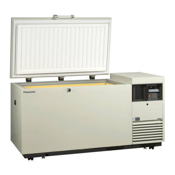
Ultra-Low Temp. Freezer
MDF-394
MDF-393(N)
FILE No.
SANYO Electric Co., Ltd.
Biomedical Business Division
SM9910175
Advertisement
Table of Contents


Need help?
Do you have a question about the MDF-394 and is the answer not in the manual?
Questions and answers